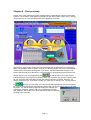
1
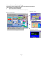
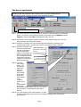
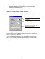
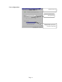
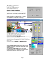
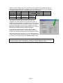
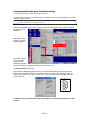
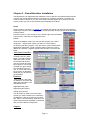
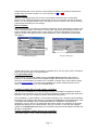
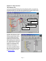
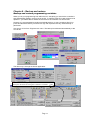
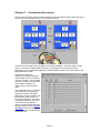
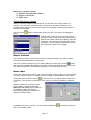
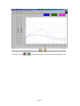
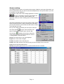
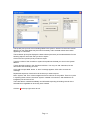
Eldar Shany
Galileo and Elgal
PC Center
Version 7.15
User manual
Edition 3 – December 2003
P.N. 0700371272
Page 1
Page 2
CHAPTER 1 – PC AND WINDOWS. .................................................................................................3
SYSTEM REQUIREMENTS ........................................................................................................................3
WINDOWS 95/98/XP TOOLS ..................................................................................................................3
CHAPTER 2 - INSTALLATION..........................................................................................................5
Software kit including:......................................................................................................................5
Installation: ......................................................................................................................................5
Software Initiation and Preliminary Settings ................................................................................... 6
THE SERVER APPLICATION ....................................................................................................................7
Add/Remove controller, Register controller’s properties.................................................................8
Modem settings:................................................................................................................................9
Line configuration: .........................................................................................................................10
THE ‘CLIENT’ APPLICATION ................................................................................................................11
Language Setting:...........................................................................................................................11
DISPLAY CENTER INSTALLATION ........................................................................................................11
PC Center Program Troubleshooting.............................................................................................13
COMMUNICATION NETWORK TROUBLESHOOTING ..............................................................................14
COM-TESTER ......................................................................................................................................14
Communication Port Test...............................................................................................................14
CHAPTER 3 - DEMO/SIMULATOR INSTALLATION.................................................................15
Add virtual controller: ................................................................................................................15
Elements: ....................................................................................................................................15
Outputs: ......................................................................................................................................15
Analog inputs: ............................................................................................................................16
Discrete inputs: ...........................................................................................................................16
Co-responding client: .................................................................................................................16
Loading variables file of a real existing controller. ....................................................................16
Sending modified variables back to the controller. ....................................................................16
CHAPTER 4 - FINDING YOUR WAY..............................................................................................17
SCROLLING MENUS ..............................................................................................................................18
CHAPTER 5 - FILES STRUCTURE. ................................................................................................19
THE PROGRAM FILES ...........................................................................................................................19
THE DATA FILES ..................................................................................................................................20
DATA FILES IN VERSIONS WITH DATA BASE SUPPORT. ........................................................................21
FOR FURTHER INFORMATION REFER TO THE WINMAN MANUAL. CHAPTER 6 –
BACKUP AND RESTORE..................................................................................................................21
CHAPTER 6 – BACKUP AND RESTORE. ......................................................................................22
BACKUP AND RESTORE PROGRAMMING VARIABLES ............................................................................22
Restore: ..........................................................................................................................................22
Restore: ..........................................................................................................................................23
Changing the controller’s PLC. .....................................................................................................23
CHAPTER 7 – COMMUNICATION CENTER . .............................................................................25
CHAPTER 8 - WINMAN. ...................................................................................................................27
Exclude and include columns .....................................................................................................28
EXPORT TO EXCEL...............................................................................................................................28
MAKE CHART ......................................................................................................................................28
SCREEN SETTING. ................................................................................................................................30
Table 1: Data codes. ...................................................................................................................31
Table 2: Data codes in versions with database support ..............................................................31
CHAPTER 9 - GALILEO DATA .......................................................................................................32
PREPARE YOUR CENTER TO WORK WITH DATA. ...................................................................................32
Page 1
Build your own reports. ..................................................................................................................34
Tab 1 – Valve accumulations..........................................................................................................34
Tab 2 – Meter accumulation...........................................................................................................36
Tab 3 – Flow and sensors...............................................................................................................37
Export sensors:...............................................................................................................................37
Tab 4 - Irrigation information ........................................................................................................39
Tab 5 – Meteorological data ..........................................................................................................40
SET YOUR PHYTOGRAPH .....................................................................................................................41
Page 2
Chapter 1 – PC and Windows.
System requirements
System: Microsoft Windows 95/98/Millenium
CPU:
Pentium 166 or higher
RAM:
32 MB at least
Free hard disk space:
Important!
The PC power socket
must be well grounded
500 MB at least
COM port: free 9 pin port, defined as either COM 1-4
CD ROM drive X24 or faster.
Windows 95/98/XP tools
In the next few chapters we are going to discuss a lot about windows tools. We are aware that
some of the new users have a lack of experience with windows. For the new user: some
windows tools:
Desktop
Shortcuts to
programs
Start menu
Running
applications
(folded)
Start button
Task bar
Close button
Smart icons
Application
scroll-down
menus
Horizontal
scroll bar
Maximize/size
button
Minimize
button
Application
window
Status bar
Page 3
Vertical scroll
bar
Microsoft Windows is an operating system. Without an operating system your PC is nothing
more then a pile of metal, plastic and a few grams of silicon. The operating system is
responsible for:
Read and write files from and to the storing media (Hard disk), communication sources and
other devices.
Read your commands from the keyboard and mouse and executing them.
Display information on the monitor.
Send documents to printer.
Manage the memory and other PC resources.
But above all it is launching other programs, which are called “Applications”. An example to
some well-known applications: MS Word, MS Excel, Internet Explorer, games and many
others. When the operating system launches an application, it allocates memory and other
required resources to the application (i.e. Internet dialer will demand to have a modem) and
ensures that the CPU (the heart of the PC) will “take care” of the program and devotes some
of its time to it.
Desktop: windows treat the area that you see on the monitor just like you treated your desk
before you had the PC: when you are not busy with something, you spread the things that you
want to have in immediate access on your desk. Your pen, your phone, your phonebook and
a cup of coffee. One and a half milliard people don’t like coffee, and wish to have tea on their
desk. That’s fine.
But when you are on a job, you just take the book and some relevant documents and lay
them all over your desk. This is what you focus on now, and you don’t like anything to distract
you.
That is exactly the way you and your operating system have to manage your desktop.
Application: Application is a program written for a certain purpose. You Open/Launch/Run it
when you need it, and Close/Exit it when finished. Some of the applications need very little
interaction with the user – they are designed to do a task and you may not even see them on
the monitor. In other applications, interact is what it is all about, like word processor. For those
you have the application window as shown on previous page, which you can minimize,
maximize, resize or move. Minimizing application window does not stop its activity and does
not free the resources it has been given.
Shortcut: a shortcut is a graphic command to launch an application.
Task bar: the task bar is usually located on the bottom part of the monitor. All the currently
running applications will have an approaching pad in the task bar. Clicking on it will bring the
application to the front. Another way to move from one application to another is to hold <Alt>
key and press <Tab> key.
Left mouse button - used for operating pointed applications and controls inside the
application, for drag items and move or resize them, making choices in menus and dialog
boxes.
Right mouse button – operates the most related sub-menu regarding to the pointed item.
Startup menu: A spatial folder that launches its content whenever your PC restarts (reboots).
Most critical application offers you to allow them to place a shortcut in the startup menu during
the installation process (Elgal Center does). But even if you fail to do so – you can always add
or remove shortcuts there by your need.
To learn more about Windows facilities, please refer to Microsoft Windows manual.
Page 4
Chapter 2 - Installation
Prior to Installing the Software make sure that you have the following items:
Software kit including:
•
•
•
•
•
A CD with all Elgal programs. Make sure the CD you have includes the version of your
controller.
HASP protection plug (Dongle) 25 pin.
Flat cable with RJ45 plugs, length: 2m.
A 'Direct' RJ45 to 9pin female adapter plug
RS485 RJ45 to 9pin female adapter plug
Installation:
Recommendation: if you are not well acquainted with Windows, or this is the first
time you install a program for Windows, it is recommended to read the Software
Installation section in the Microsoft Windows User's Guide.
Step 1: Connect the software protection plug to the printer's port (LPT1).
Step 2: Connect the communication connection to the serial port. Make sure that you know
the port number (the port number can be: COM1 - COM4). Connect the other side of
the flat cable to the controller’s socket (direct) or the L485 adapter.
Step 3: Insert the CD to the CDROM driver and wait for the AUTORUN menu to display on
the screen.
Step 4: Move the mouse cursor to the Elgal center and click the left button. A sub-menu will
appear. Choose the Elgal center 5.05 (or any later version yet to be) and follow the
instruction orders. Choose your preferred language. If none of the suggested
languages are suitable to your Windows language – point to the English. Approve
placing shortcuts on your desktop and startup menu.
Step 5: Return to the CD’s Autorun menu. In case you don’t receive it – just open and close
the CDROM driver’s tray and wait about 20 seconds. Click the Elgal center again
and then on the project suitable to your controller. Follow the instructions. Choose
only the languages you may need.
Step 6: Return to the CD’s Autorun menu. In case you don’t receive it – just open and close
the CDROM driver’s tray and wait about 20 seconds. Move the mouse cursor to the
WinMan and click. When it comes to the point of asking you to choose the group in
the Start menu – you will be advised by the program to create a new group called
Winman. You can either approve it or click on the already existing Elgal group below.
Proceed and approve all other options.
Step 7: Close the Autorun and remove the CD from the driver. Reboot your PC. The Elgal
center is supposed to open.
Page 5
Software Initiation and Preliminary Settings
Each time you start the computer the Elgal control program starts running automatically.
Those are actually 2 interconnected programs:
•
Center display program (EldarClient)
•
Communications center program (EldarServer Application).
Main Screen - Climate
Main Screen - Center Display
Main Screen - Irrigation
Server application
Main Screen - Open Fields
Page 6
The Server application
Attention! The communication center must never be closed. Closing the center will stop the
operation of the main software of the computer. When you finish working with the
communication center, minimize the screen using the Minimize button.
Communication errors
accumulation
Communication ON/OFF control
Communication status indicators
Step 1: The server application is initially locked for changes to avoid damage by unauthorized
person. To unlock it Lclick (click with the left mouse button) on the Options and then
Log On. Type the letters SU in the dialog box and Lclick OK.
Step 2: Mark all the communication ON/OFF controls to OFF position using your Lclick. All
lines should be now marked with red X.
Step 3: Rclick the controller’s line. From the submenu that opened (if necessary) Lclick
change COM number. Type the new number in the dialog box and Lclick OK.
Step 4: Rclick the controller’s line.
From the submenu that
opened (if necessary)
Lclick change COM
setting. The changes you
will do here will serve all
the controllers that will be
connected to the same
COM port. The following
dialog box will open:
This check box
should be checked
when
communicating via
This check box
should be checked
when communicating
via radio
Step 5: Lclick the
Com setting
button. The
only set you
have to do
here is to
adjust the
port’s speed
to the same
speed you
have defined
in the
controller
(code 71 #2).
It is
recommended
to start with
the highest possible speed, and only if you get too
many errors try to reduce speed. Click OK to
approve.
Step 6: If you use modem or RF communication you have
to enter the regarding options and do the settings according to the manufacturer
specifications.
Page 7
Step 7: Click OK to close the COM setting and then click the communication control ON. The
2 status indicators should now blink green lights, where the left indicates “Transmit”
and the right “Receive”. In case you don’t obtain good communication refer to
communication troubleshooting manual.
Step 8: Click Options and Save settings. Skipping this step will cause lose of those
changes on the next PC’s boot.
Add/Remove controller, Register controller’s properties.
If you have more controllers than lines in the server – you will have to add more lines. Click
Options and Add controller. The next dialog box will appear:
No. of new controller
COM No. to which the new controller
is connected
No. of control program of the new
controller
No. of the display menu of the new
controller
Text appearing in the "Note " line
intended for the controller
This box enables you to do all the required settings at once. Refer to the version page in the
Elgal Setup manual to find out the correct PLC and Display numbers. Those numbers will
become curtail if you will have to change the controller’s version or type from within the PC.
Click OK and save settings in options menu.
The new line is now added to the server window. You may have to enlarge the window to
view it by dragging its lower boundary down: when you place the mouse cursor on it, the
cursor changes to ↕. Hold the left button and drag it downwards until you see the new line.
Click the communication control to start communicating with the controller, and perform Save
settings again.
Page 8
You may remove a controller from the server at any time, or change the parameters of each
one of the controllers installed in the server. Pressing the right button of the mouse on the line
of the controller, which you wish to change, and selecting the item you wish to change from
the menu.
Pressing the right button of
the mouse on the
controller's line will open
the menu appearing here at
the right.
Communication errors accumulate for each controller separately. After 5 continuous fails an
alarm will burst on to your desktop. The errors accumulated can be cleared implicitly by
command or at any exit and resume of the program.
A controller connected to the PC center receives a clock updating every round hour. You can
change the updating cycle or totally cancel this function by clicking options and options
again. The dialog box that opens enables changing other things but it is not recommended to
change those default settings.
Restoring all the user set points and programming variables is recommended as a system
backup once a month. Another possible use is if you need to discuss your program with our
technical staff, and you want to send us a copy of the content of your controller. The system
automatically saves everything you send from the PC to the controller in a file under the
program folder but you may give your backup name and that can help you revert to an older
program if something went wrong. More about it in backup chapter.
Modem settings:
Dial number: modem
telephone number
connected to the controller
in the field
Line configuration
Page 9
Line configuration:
Advanced options
Modem Volume select
(During dialing)
Modem Baud rate selection
(should be the same as the
controller's baud rate)
Page 10
The ‘Client’ application
Language Setting:
Pressing on the Language setting button
will open the following setting box:
Display Center Installation
Note: in order to execute several sections of the
installation, it is necessary to enter the proper code in the
"Options" menu. (log on code - password: 7968 or 'SU')
The first step should be to install the control units in the
computer, according to the systems that operated by the
existing controllers. In the following we give an example
of the installation of a system with two controllers:
Controller No. 1 will be used for climate and irrigation control in one greenhouse, and
Controller No. 2 will be used for climate control in two greenhouses.
Click "Edit - Add/remove units" menu. This menu opens a
box, which allows us to install units of any type from the
systems previously installed from the diskettes.
Choosing a system and clicking Add item creates a new
System window on the desktop. Hold the left mouse button on the blue top of
it and drag it to the best position and drop.
The new window you have just set is still idle. It doesn’t know what
controller to look upon and what segment in the controller’s memory. You
have to “teach” it.
On the system menu click Options and Change settings.
Set the controller number first. After clicking OK this number
will display on the top left corner of each window of this system
following the # sign.
In the dialog box System number you can enter a short
intuitive description (up to 11 characters) for this system. That
string will be the title of each window of that system.
Page 11
Irrigation systems always placed in the middle memory segment of Elgal 2000 and the top
memory segment of Elgal 12/24. Therefore you are not asked to choose a memory segment
to Irrigation systems. However, with greenhouses it is not so simple:
Controller
Elgal 2000
Elgal 2000
Elgal 12/24
Elgal 12/24
PLC
2CL_IR
4CLIM
CL_IR
2CLIM
Segment A
Greenhouse 1
Greenhouse 1
Greenhouse
Greenhouse1
Segment B Segment C
Irrigation system
Greenhouse 2
Greenhouse 3
Segment D
Greenhouse 2
Greenhouse 4
Irrigation
Greenhouse 2
The handle on the right side of the dialog box has to be
dragged to the correct segment for this particular system. A
mistake might be distractive. If you will point a climate system to
a memory segment that hold an irrigation system – you will see
nonsense in the system, and if you try to program it you may
damage the FPROM and have to call for service. The numbers
below show the address where the segment begins.
If you define 2 system windows with the same controller
number and the same segment – they will display the same
values. Every change you will make in one will reflect the other.
After all the systems have been set, you can arrange again the
location of the windows and their size as you wish, and save all
the systems you have defined (in the "Options - Save" menu).
Remember! You must not close the main menu of the display center. Closing this menu will
cause the closing of the central program, including the communications center. If you wish to
work with another program, minimize the main menu using the "Minimize" button.
Page 12
PC Center Program Troubleshooting
When the computer is operating, only the Management Program appears, and I can't
initiate the Central Software (Communication + Display)
1.
2.
3.
Make sure that the software protection plug is properly connected to the
printer port.
Make sure that the printer port is working properly.
Check the protection plug using the ComTest software.
When I initiate the Central Software, the following error message appears:
"Create Comm error"
1.
You selected a port (COM) that does not exist or is being used by another
element of the computer (for instance the mouse or the modem).
I receive many communication warnings, and I can't see the data coming from the
controller
1.
2.
3.
4.
Make sure that the controller's number is identical to the one set in the
computer.
Make sure that the communication rate is identical for the controller and
the computer.
Make sure that you are using the correct communication connection
(Direct, for a direct connection, and 485 for a RS485 connector).
Check the communication hardware using the CommTest software and
the "communication test" plug.
The communication is disrupted while using the modem / after installation of the
software and connection of the communication center the mouse stops working / there
are disturbances in the communication from time to time
Check that there aren't any "conflicting devices" (hardware mismatch) at
the serial port used for communication (control panel - system - devices
manager - ports (com&Lpt) - communication port (COMx) - properties resources).
Page 13
Communication Network Troubleshooting
(Communication between PC and Elgal Controllers)
A special program that is used for testing communication ports and plugs is provided
with the Elgal software.
Notes: Test 1 and 2 requires a special test plug and will fail without it.
For more information see Chapter 2, p 11-12.
COM-tester
Load the COM-tester program by clicking its shortcut in the “Elgal Center” folder, located in
the Start Menu of
Windows.
After opening the
program, the next
window appears:
Each time a test is
run, a message
appears in the
window to the left of
the screen telling you whether the test was successful or not.
Communication Port Test
Disconnect the RS485 plug from the PC port. Use a special test plug with a short circuit
between TXD and RXD points on the COM Port that you want to test. Select the port you
want to test (COM 1 – 4). Click on “Test Com”. If you want the test to be longer, click the
“Long Test” box.
9 Pin Test Plug
5
4
3
2
1
9
8
7
6
Troubleshooting communication with L485 adaptors is widely described in the L-485
manual.
Page 14
Chapter 3 - Demo/Simulator Installation
The Elgal demo is an application that enables the user to practice, simulate and demonstrate
a work of the control software without connecting to a controller. Instead of a controller you
create a virtual controller on your PC. Each virtual controller appear as a “panel” on the PC
monitor, where you can set I/O elements and manipulate their values.
Install:
Perform steps 3-6 in page 1 of chapter 2 of the Elgal PC manual. Uncheck the box regarding
to placing a shortcut in the startup folder to prevent automatic lunching of the Center when the
computer starts.
Point the mouse on “Test versions” on the bottom-right of the CD ROM’s
Autorun menu. Click and pick “Elgal demo 3.03”.
Lunch:
Once the installation is done you can start the program from “Start” >
“Programs” > “Elgal center” where you find Icon named “Demo”.
On lunching the demo program, The “Sim server” opens instead of the
Elgal Server application. Virtual controller (panel) number 9 is set by
default as a Climate + Irrigation greenhouse controller. The others are
blank.
Add virtual controller:
If you wish to add a virtual
controller click the <Add>
button. The add controller
dialog box opens. Chose
the number and the PLC
type and version and click
OK to approve. The virtual
controller you get is empty.
No I/O elements set on it.
You, of course, will want to
set your own I/O elements:
those that you will need for
the simulation.
Elements:
Click <Panels> and <Add
I/O Element> and follow the
dialog box instructions. The
valid elements are:
3
Digital (Discrete) input
Digital (Regular) Output
Analog input (Sensor)
The ID number is curtail. This is the same
number you have to define in the controller’s
I/O definition. Click OK to approve and close
and “Add” to continue setting. When done, all
those elements will be displayed on the panel
and you will be able to change them.
Outputs:
Page 15
Output elements are only for observe. The program according to a command changes their
position from the virtual controller. You can view them as ON or OFF.
Analog inputs:
When you set Analog inputs you must set a scale that is identical to the co-responding
sensor’s scale. Analog inputs has a dial that opens when you click them with the left mouse
button. You can drag the handle to the value that you want to transmit to the virtual controller.
It will stay like that until your next change.
Discrete inputs:
Most Discrete inputs are useless to simulation unless they can be activated by an event in the
virtual controller program. For instance: A water meter input must start transmit pulses to the
virtual controller upon irrigation start. In other words: it should be depended on main valve
opening. Click the new panel with the right mouse button. Click <Conditions> first and then
<Set pulse>.
Check that box
Set to Dig. Output
Set to the corresponding output
Tune the pulse to the
required frequency.
Set pulse dialog box
Condition dialog box
In other cases, like if you want to simulate a condition input, you can simply click on the panel
with the left mouse button to change its status.
Co-responding client:
Upon lunching, the simulator initially lunching the Elgal Client application with systems
windows for one greenhouse and one irrigation system that are set to controller #9. If you
want to do your simulation on another PLC or another controller, refer to the orders in pages
6-7 of the Install chapter. You have to set yourself a new system window and set it to the
same controller number as you set in the Sim server.
Loading variables file of a real existing controller.
You can load a variables file of a real existing controller. That feature is helpful for whoever
deal with service to others. Any user can send his variables file via E-mail and the expert who
receives it can open it on the demo program and analyze the problem.
Click <Variables> <Load variables> on the virtual controller’s menu. Windows Open file dialog
box takes you by default to the directory C:\Program files\Eldar\Elgal center\Client\Pfiles. That
is the folder that the Elgal center automatically stores the variables of controllers that
operated by your PC, but it is not necessarily the location where you placed the received file.
Navigate the dialog box to the file and load it. Once you do that – if you open the engaged
system on the Elgal Client application you will view the set points of the loaded controller and
be able to change them.
Sending modified variables back to the controller.
The current version – 3.03 – does not support that feature.
Page 16
Chapter 4 - Find your way.
Version 2.04 of the greenhouse control software brings a great deal of comfort in the human
interface. The access to most tables is possible from the main system screen only by clicking
on the referred icon. Let’s first take a look at an application’s window:
Scroll down menus
Controls
Almost every object on the screen becomes associated with its information or programming
table. Those objects called “Controls”, and you can identify whether the cursor is pointing on a
control when it becomes a hand symbol. If you click it, the associated table will open. The
window title will help you to identify if it is an information or programming screen. But there is
another way to know: the programming key
on the top left corner of the window
indicates that this is a programming window. When you see it like that you will be able to view
all your set points and parameters as they are retrieved from the controller. However, you
cannot modify them yet. If you wish to modify you must click on the key icon. The key will turn
to
and now you can either move from parameter to parameter using the arrows or
by a mouse click. At that point that window is locked and you cannot leave it until you click the
key again. You will be asked to approve sending the changes you
made to the controller. Clicking “OK” will complete the procedure
and “CANCEL” will enable you to leave the window without changing
anything in the controller.
Page 17
When you enter a programming screen you may see the parameters values in different
colors. A red number indicates mismatch between the value in the controller (what you see)
and the value that was previously saved in the PC. That will happen whenever you change
something from within the controller’s keyboard.
To view the values from the PC file press “Shift” before opening the screen to
programming.
To revert to the values that were previously saved on the PC – hold down the “Shift”
key while clicking the programming control. Then leave the “Shift” and click the key
again.
To save the new values from the controller to the PC file – just click the programming
control once for opening and once for closing. Here too, you will have to approve the
action.
Scrolling menus
The other way to access information and programming screens is through the scroll-down
menus. Most of the items that have controls on the main screen are accessed from Main. In
some cases you may find it faster to use this access method: the options parsed in a “root”
shape and you can open the final destination without having to “dig” through other screens.
The options placed under Setting were intentionally moved away from the graphic screens to
avoid changes with no intention. All the controller and system settings are sub to this menu.
When you are doing a lot of
work in the environment of
controller setting, like in new
installation time, you have the
option to open the system
screen instead of starting
from “Settings” all over to
each subject. Go
<Settings><Controller><Syst
em screens>. The next menu
comes up:
Attention! Take care when making changes in
settings. Make sure you know exactly what you are
doing. Read the Elgal setup manual carefully.
Register every change you do in the controller’s ID
The logbooks are accessed from Logs. There is no graphic control to logbooks.
If you want to access meteorology facilities from irrigation system you will find it under Gen.
Info.
Page 18
Chapter 5 - Files structure.
The program files
If you do not change the default files location when installing the software – the program will
automatically be installed in a sub folder under “Program files” folder. You should know it only
as general information. You never need to get in and deal with its constants, except for some
special cases. The program files structure described in the layout below:
Contain the MMI software and
the controllers mirror files.
Demo program – not
always installed
Copyrights protection program
Contain all the graphic screens
sub folded by project.
Contain the
communication center
Under the “client” folder you can find 2
sub folders: Afiles and Pfiles. In those
folders you can find the mirror files of
your entire existing controller. The file
created immediately after sending
programming to the controller at the
first time, and named by its number (3
digits) suffixed by [.var]. As long as you
do the programming from within the PC
only – that file will be the exact copy of
the controller’s memory. In case that
the main CPU card will have to be
replaced – you will be able to restore
the old data in a few minutes.
If you incline to do programming from
the controller’s keyboard from time to
time – we recommend you to perform
data backup once a week or two. You
will find more detailed instructions in
the backup chapter.
Page 19
The data files
The data files are collected by a system
number and not by a controller number.
The controller number does not play a
role here at all. The files are saved in the
folder C:\ELDAR and the file name
contains 8 digits, a dot and the suffix PRN.
Those are ASCII (text) files. The files
names are important to understand:
11210031.PRN
The month
The day in the month
The system number
The file code (type of data)
Every system creates several files every
day. Each file contains different kind of
information regarding to the system type. It
means that a file named 02270013.prn created by a climate system and a file name
02270113.prn created by irrigation system has the same date and the same code but totally
different information. That explains why it is so important to give a unique system number to
every system connected to the same PC.
Many of the files are very small. Some of them contain few bytes only, but due to Windows95
files system limitations they capture a block of 1Kbytes. This problem was improved a great
deal by Windows98 files system, but still, it would be honest to say that our program has a
great appetite for Hard-disk resources. Therefore, if old data is not a matter of daily interest
for you - it might be better to Zip it (Use WinZip© or any other zipping program).
Once a year the WinMan program takes all the ending year’s files and moves them to a new
folder named under the ending year (4 digits).
For further information refer to the Winman manual.
Page 20
Data files in versions with Data Base support.
Application versions that utilize Data-base suppot can be identified by the letter ‘D’ in the
version name. Open Field V 2.X has a database support all through and therefor will not be
marked with the letter ‘D’.
Some characteristics in the PRN files have also changed, which lead to the need to change
the file name format to distinguish from files generated by older versions.
The change is in the file code: 2 digits were added, and offcouse the prefix is now of 10 digits
instead of 8. See the example below.
1121003201.P
The month
The day in the month
The system number
The file code (type of data)
Files of Greenhouse irrigation system have additional 20 (two, zero) in its code.
Files of Climate control system have additional 10 (one, zero) in its code.
Files of Open Field irrigation system have additional 30 (three, zero) in its code.
When you install a version that supports database, a new table is installed in the Winman
reports tables. This table’s name is as the version name. The next time you launch Winman
click the ‘File’ menu and ‘Change project’ command. The new version will appear in the
selection box. Select the version as the one you have on the controller it’s data you want to
view.
For further information refer to the Winman manual.
Page 21
Chapter 6 – Backup and restore.
Backup and restore programming variables
When you do your programming from within the PC, everything you send to the controller is
also automatically saved in a mirror file in the PC. In case the main CPU card will have to be
replaced – you will be able to restore the mirror file to the controller in a few minutes.
However, it is recommended to perform periodically backup. In some occasions like PC or
just a hard disk drive failure you will be in a high risk of painful recovery unless backup is
performed.
One way to do it is from “Elgal service” menu. The backup here directed automatically to the
xxx.var file:
1
2
4
3
6
5 – The process
The other way is through the Server application:
2
1
3 – Windows File dialog box opens: Choose location and a
descriptive file name for saving this controller’s variables.
Page 22
The procedure shown on the status line:
Restore:
Both ways work vise versa for restoring.
If you backup through the server application you may send this file via E-mail to your dealer or
consultant, and they will be able to run this program on their own PC and analyze possible
program mistakes.
You can also copy one controller to another, but be careful! You copy a whole controller and
not a system. Both source and destination controllers must run the same PLC.
Changing the controller’s PLC.
Elgal 2000 (only) controllers that run the PLC on a “flush” memory can be upgraded to a
newer version from the PC by sending a new program (PLC). The whole procedure is long
and risky, and in normal cases should only be done by authorized technician. However, we
present the method here: you my find yourself in a situation that you will need it. Reading
this manual will not skill you to perform your own upgrading. It is only describing the
steps to send PLC, but the whole controller must be reprogrammed.
The PLC file, besides residing in the controller’s FPROM, is found in the C:\Program
files\Eldar\Elgal center\server\Plc folder. It is actually a combination of 2 files that must be
suitable to each other: the control program and the display strings table of the desired
language.
Program
Language
Elgal
PLC Display
2 Climate chambers,
English
10
12
1 Irrigation head
Spanish
13
Russian
14
Hebrew
11
4 Climate chambers
English
20
22
Spanish
23
Russian
24
Hebrew
21
Open Fields irrigation English metric 30
32
English USA
Spanish
33
Russian
Hebrew
31
2 Poultry houses
English
01
03
Spanish
02
Russian
Hebrew
01
Page 23
Galileo
PLC Display
60
62
63
64
61
70
72
73
74
71
80
82
89
89
83
81
51
81
53
52
51
Before attempting to send PLC and Display, you must verify that the correct PLC and Display
are registered to the controller that you upgrade. The registration is in the server application:
Log on (type SU).
Disconnect the controller from communication.
Rclick the mouse on the controller’s line: the option menu opens.
Click Change PLC and fill-in the PLC number.
Rclick the mouse on the controller’s line again.
Click Change display and fill in the display number.
Renew the communication
You should see the full detailed line of the controller with the correct PLC and display
numbers on the right side (see the picture on the top of the previous page). Now you are
ready for the next step.
Sending PLC too, can be performed via the “Elgal service” menu in the Client application, or
via the server.
Make the controller Not active (511 in the controller’s keyboard
In the server: click Commands and Send PLC. The procedure may take a few minutes
(depend on the communication quality). At the end you will get the prompt “PLC OK”. Now
click Commands again and Send display. That action takes a bit longer, and the controller’s
keyboard locks itself until it ends.
In the Service menu: click Send PLC. The procedure may take few minutes (depend on the
communication quality). At the end you will get the prompt “PLC OK”. Now click Send menus.
That action takes a bit longer, and the controller’s keyboard locks itself until it ends.
The old parameter does not fit to the location of the new PLC.
Before you make the controller Active again, you must open every
programming screen and revert to your old set points.
Page 24
Chapter 7 – Communication center.
Edit the communication center is the last necessary step to enable exporting and importing of
sensors and other properties from one controller to another.
The access to the table is from the Elgal service menu (Settings > Controller setup > Elgal
service > Common variables table). However, the CV editor is not a part of the client
application. It is an independent application called CVEditor placed in the server folder in the
Elgal installation folders.
the old terms display as
“Sell”(Export) and “Buy”(Import).
The left fixed column of numbers
– the row number – is the number
that every controller in the system
will be able to register in its
“Sensors from communication”
table.
The registration here is according
to the numbers you previously
defined the items in the export
(Sell) table of each controller, and
the controller number as it is in
the server application. The notice
is important mainly for future use.
You will find it very difficult to
trace if you will not describe what
each line means. Refer to Export
and Import manual in the Elgal
Setup manual for a full description
of those actions.
Page 25
The process of transferring properties between controllers is not simple. You are advised to
draw your own connection table to help you to navigate around. We shell give one example
here:
Location
Step
Wind speed sensor connected to
controller 1 input 10
Prog. code
Hardwar
Controller 1
Define input 10 as 4-20mA, Min.= 0,
Max = 160
73
Register sensor number 10 as General
sensor No 3
743
Register General sensor No. 3 as
Export (sell) No. 1
514
PC
Register Parameter 1 from controller 1
as communication parameter No. 2
Controller 2
Register communication parameter 2
as imported sensor No. 31
744
Register sensor No. 31 as wind speed
for controller 2.
745
Note: you may have to close Elgal center and relaunch it to complete the procedure.
Page 26
Chapter 8 - WinMan.
Chapter 4 of this manual book has described the structure of the data files that created on the
PC by the control systems. Winman is the tool to generate clear and easy-to-read reports
from this information. Winman is a set of 2 different programs: Winman and Screen Setting.
Winman is where you retrieve your data on the PC. The program itself has a reach and
interactive online help and therefore this manual will not cover all its actions very deeply.
On launching the program you get the welcome screen. This screen, among other things,
offers you a set of pre-defined reports that are the most common reports. Those reports may
be enough for the beginning user or a single greenhouse project.
The first step you have to do in order to prevent confusions in your future work is to define
your existing systems with a descriptive string.
Click Tools and Systems on the top menu. The systems dialog box will open:
You have to register your existing systems
one by one with descriptive names. The
numbers you select on the left box refer to
digits 5-7 of the file name. Those 3 digits in
the file name, in case you forgot, are given by
the system number as it defined in the
controller (Code <521> and <532(n)11>) or
the controller number in Open field system.
Give each one a name is important, because
in a greenhouse project, the reports set
includes both irrigation and climate reports. It
is a common mistake to retrieve an irrigation
report with a climate system number or vise
versa. In both cases you will get nonsense.
After clicking OK, click “Cancel” to close the
to reopen it, now you can see the systems in the pick-up list. Click a system,
screen, and
click a date, click a report and then Open. If the data file exists on your PC it will display a
table report.
Page 27
What can you do with a report?
Exclude and reinclude columns.
Export to Excel file.
Make chart
Exclude and include columns
When you view one of the pre-defined reports, you will often have empty columns. For
instance: if you only have 3 fertilizer pumps, but the report allocates 8 columns for all 8
possible fertilizer pumps. Those columns make you a great deal of scrolling right and left to
view the important data.
You can use the
opens:
button to decide what columns to view. The column view dialog box
Hold the “Ctrl” button down and click the columns
you want to view. A click turns it blue (display) and a
second click makes it blank (don’t display). Click OK
to approve. This change will only take place during
this session. The next report of that kind tht you will
open will display all the columns again.
Export to Excel.
You will want to export to Excel when you have to manipulate data or you want to make a
report of few days that based on a daily report.
button
The Excel must be launched on your PC before attempt to export a file. Click the
and chose the template that suitable to your needs. The process takes about 20-30 seconds,
and at the end Winman is Automatically switching you to the Excel surrounding.
Make chart
Chart is the easiest way to have a quick overview of large amount of data. You can get a daily
or monthly values of sensors in a graphic way and visually compare between charts. While
on the menu bar. You will be asked to select up to
viewing the report, click the chart tool
4 columns to view from the current report. Each column you select will display in a different
color.
Winman enables you to display various
types of data on the same chart, pay
attention to the Y-axis. Each column will
get a different range. The range is
automatically optimized according to the
highest and lowest values.
If the differences are not too big – you can use the equalize tool
size of the smallest Y-axis.
Page 28
to shrink all Y-axis to the
Clicking on a chart legend enables you to use
and
for it. Proceed until you have the
whole view the way you want it. At that point, if you want to view the previous or the next day,
you better just click
or
instead of retrieving the report and then generating the chart.
Page 29
Screen setting.
The standard reports refer to one system and one type of data for each report. But what if you
have 5 greenhouses and you want to view their temperatures in one report? What if you want
to compare it to solar radiation?
The answer to that is the Screen setting application. Click the
and go to “Programs” and to the group where you
installed the Winman. Click the “Screen setting”. The
application shoes you all the existing report on the left side of
the screen.
The first proposed step is to study the content of each report.
Open the reports that are usually containing the information
you want and note the code number and the column number
of the data that you need.
Now you are ready to generate your own report. Click the
new report button
and give name and title to the
report. A blank report window open. Use the 'add
repeating for as many columns as
record' button
you are going to need. Do not forget the time column
– mostly placed in the first column.
Source: the column title in your own language.
English: the column title in English.
Format: the position of the decimal point.
Column: the order number of the column that you want to display in the source file.
Code: the file code (see table below).
System: the system (greenhouse etc.) number as defined in the controller.
Page 30
The table is automatically saved. The next time you will launch the reports window you will
see it there. If you specify a number in the “system” field in the screen setting – you won’t
have to specify it in the report window.
Attention! When you combine a report from several systems, make sure all the systems will
have the same data collection cycle (in minutes). Different cycles will result a report that will
make no sense. The time column will be taken only from one system and it may not fit the
other system timing.
Table 1: Data codes.
Code
1
2
GH irrigation
Sensors daily
3
Irrigation
session
Valves daily
Drainage info.
4
5
6
7
8
9
0
Climate
Sensors daily
Meteorology + outputs
monthly
Windows and Outputs oper.
Daily
Day Tmp. monthly
Day Hum. Monthly
Day Gen. Sns. Monthly
Night Tmp. monthly
Night Hum. Monthly
Open field
Sensors daily
Meteorology daily
Irrigation session
Sensors monthly
Water flow
head/time
Valves
accumulation
Night Gen. Sns. Monthly
General counters daily
Table 2: Data codes in versions with database support
System
GH
irrigation
Climate
Chamber
Open field
Code
201
203
4
205
0
101
2
103
4
5
6
7
8
9
0
301
303
304
306
307
308
309
Report content
Sensors daily
Irrigation session
Valves daily
Drainage information
General counters report
Sensors daily
Meteorology + outputs monthly
Windows and Outputs oper. Daily
Day Tmp. Monthly
Day Hum. Monthly
Day Gen. Sns. Monthly
Night Tmp. monthly
Night Hum. monthly
Night Gen. Sns. Monthly
General counters daily
Sensors report
Irrigation session
General counters report
Water counters period report
Valves period report
General counters period report
Operate time period report
Page 31
Poultry
Summary daily
Data + sensors every
hour
Data + Sensors every 10
min.
Scales distribution
Scales every hour
Scales daily
Chapter 9 - Galileo data
If your controller is connected to a PC – it becomes a powerful data logger. The following data
can be logged to your PC:
Irrigation sessions – a summarized, event based logging at the end of each session.
Valves accumulation
Water meters and general counters – Velocity, Accumulative and time period pulses.
3 additional tools are used to view and generate reports from this data:
Winman – An application by Eldar-Shany that is provided with the PC-Center kit. See chapter
8.
PhytoGraph – An advanced application by Phytech that can be purchased separately.
Galileo Data – The subject of this chapter.
Winman is the old familiar tool that is used since the DOS days. Its disadvantage is being
based on daily text files; hence the generation of multi days report is impossible. Galileo PCCenter 7.2 and its following versions, enables saving the data in MDB format – a standard
format that can be launched by most known data processing tools such as MS Access and
Oracle.
Galileo Data is an application for viewing and reporting Galileo generated data. As for now it
is installed within the Open-Field application installation and will appear on your desktop as
icon.
Prepare your center to work with data.
Two conditions are required to enable you to work with Galileo Data:
You must check the Data box in the Server application.
Click the Server icon
in the task bar and perform “Log on”.
Click ‘Config’ > ‘Options’ and check the Database box. Click OK.
Your controller’s PLC must be a version that includes the letter ‘D’ after the second dot.
From this moment, the file Elgal.mdb file is created in C:\Program Files\Eldar\Elgal
Center\DB. All data that is generated by any controller connected to that PC is saved in that
database.
Page 32
Launch Galileo data.
Double click the
icon to launch Galileo Data.
Tabs
Item selection
Time frame
•
All the menu options are under ‘Tools’ command.
•
The 5 different types of reports are arranged in 5 tabs.
•
The ability to choose a time frame exists in every tab.
•
In every tab you need to select a reported item. However, setting pre-generated reports is
advised in order to ease the report generating process.
Page 33
Build your own reports.
The following steps are advisable in order to improve the accessibility to the very data that
suits your own site. You may still, at any time, make a query and generate a report by picking
the reported items and a time frame. But when it comes to frequently required reports – these
few steps will make your work with Galileo data much easier.
Set names and costs:
Galileo Data can calculate costs if you enter the appropriate
information.
Click <Tools> and <Set fertilizer name>.
Fill descriptive names of fertilizers in accordance to the
description you gave in the controller (Open field only) in code
4212#3. Although 30 fertilizer pumps are available in Galileo
Open Field 2, we assume that no more than 10 different types
of fertilizer will be in use within one site. If you link the injector
to a fertilizer name you will be able to obtain a cost calculation
report.
Set valves groups:
Valves can be grouped just the way you want them in the
accumulative reports. Mostly you will prefer to have all
valves of a certain plot in one report. However you are not
restricted to plots and not even to controllers.
Click <Tools> and <Set Valves group>. Give a descriptive
name and set valve numbers in the right column. In
Galileo Open Field, the ‘System’ column is the controller
number as appears in the server’s communication list, or if
overridden – the number set in the controller in code 72#2.
In Galileo GH Irrigation it’s the system number set in code
5211#2. If you will set a system number that serves a
climate or poultry system – the retrieved data will not
make any sense to the report’s labels.
Figure 1
Figure 2
Once all group members are entered, click the ‘Save
group data’ button. You may click the ‘New group’ button
for another group or the X at the top right corner to exit.
Tab 1 – Valve accumulations
Click the ‘Valve accumulations’ tab.
If you created valve groups you may now select a group or select a certain valve from a
certain controller.
Select time frame that you want to focus on.
Click ‘Data’ button to retrieve the report.
Page 34
Assuming that there is a valid data stored for the time frame – you will get the report similar to
the one in Figure 5.
In this example only valve 1 had an associated program.
You may click the graph button to view the same report as a graph:
Page 35
Tab 2 – Meter accumulation.
The Galileo Open Field software enables to define 3 types of counters: Water maters,
General counters and time counters. The greenhouse software has only general, fertilizer,
and water counters.
A water and fertilizer meter has a preset quantity. The units in the report will be according to
the predefined units.
A time counter registers operating time of an engaged component (pump, valve etc.) between
two data records. For example: if you set the system to invoke data registry every 10 minutes,
and a pump that is engaged to time counter #1 was on for 8 minutes during two registries –
the value in the record will be 8, where the maximal value may be 10. This information can be
viewed as a chart or summarized in a report.
Since most counters are used to calculate and optimize electric power consumption, it is a
matter of interest to be able to separate each portion of the day, if purchased energy has
different tariffs. Galileo Data enables you to restrict your report to one portion of the day as
defined in the controller.
Click ‘Tools’ > ‘Change day period’ if you want to select day portion or to make sure that “All
day” is checked. Click OK.
Select the type of counter.
Select system (Controller) number and the item number.
Select time frame
Click ‘Data’ for summarized table or ‘Graph’ for a chart.
Page 36
Tab 3 – Flow and sensors.
Tab 3 allows viewing a single, value-type input (an analog sensor or flow value of a water
meter), in a requested time-axis. Unlike the accumulation tab, the data here is not a count
between two data registries, but the actual value at the moment of sampling. Should you like
to have a better resolution – you have to set a shorter sampling interval in the controller.
Different controllers on the same PC may have a different sampling interval.
Click the ‘Flow and
sensors’ tab.
Select the type of element
you want to view.
Select system (controller)
number and the number of
the selected element.
Set time frame.
Click the ‘Graph’ button to
a chart. The charts in this
tab are linear.
Clicking the ‘Data’ button
invokes a tabular report. The tabular report may contain
thousands of records, and therefore advised to use only if a
certain accurate value at a certain time is needed.
Export sensors:
It is obvious that in most cases there will be a need to
compare data of several sensors and other registries. The
Galileo Data tool does not comply with such requirements.
For those who require intensive use of sensors – we propose the Phytograph by Phytech.
The 'Sensors exporting' tool indexes sensors within the Elgal.mdb file to be read by the
Phytograph.
Click ‘Tools’ > ‘Export sensors’ to open the export dialog box.
Page 37
The top left pick-up list is a list of existing tables in the system. ‘Sensors’ is the most common
table to use, but other tables may be used if necessary and if the data makes sense when
appearing on a time axis.
The left bottom pick-up list displays the data columns (the items) of the selected table. Do the
following steps for each item that you wish to export:
Click on the item (column) that you want to export.
Type the number of the controller or system that produces the data you want in the ‘System’
edit box.
Type a descriptive name in the ‘Set Name’ edit box. You may use 128 characters, but we
recommend not exceeding 24 chars.
Click ‘Add to export table’ button. A “done” message appears. Click OK to remove the
message.
Repeat this sequence of actions for all the items you want to export.
Note: ‘System’ and ‘Time’ columns appear as first 2 columns on every table. There is no point
in exporting those columns, because ‘System’ is stated in its own box, and date/time is an
integrative part of each record.
The index table is created immediately and will enable exporting all existing records of the
selected items regardless of when they were created.
Click the X at the top right corner to exit.
Page 38
Tab 4 - Irrigation information
This tab is a session-based table: A record is created on every successful ending of irrigation
session. It defers from all other tables that are time based.
Select the required program from the
required system.
Select time frame.
Click the ‘Get Data’ button.
Your query will retrieve all the
existing records of irrigation ending
of the selected program. DoubleClicking the right mouse button while
pointing at a record will open the
next view:
You may use the ‘Next’ and
‘Previous’ buttons to move to other sessions of this program. To change to another program
click the X at the top right corner to exit, and perform the query again with a different
program/system.
Page 39
Tab 5 – Meteorological data
Meteorology information is likely to be a subject for export to Phytograph. The graphical GUI
of Galileo Data application only enables you to have a quick view of one sensor at a time.
The tabular option displays all the sensors at the same time.
Select system (controller) number.
The system number is not of
importance in this case, because
meteorology conditions in a site
will be identical all over, but it
must be one of the existing
systems.
Select time frame and the sensor
you want to view.
Click the ‘Data’ button for tabular
report, or ‘Graph’ button to view a
chart of the selected sensor.
Page 40
Set your Phytograph
The Phytograph application is a subject for its own manual. The steps described in this page
are meant to ease the set of Phytograph to view Galileo Data reports.
Launch the Phytograph
.
Click ‘Project’ > ‘New provider’.
Select the ‘Eldar Galileo’ option and click ‘Next’.
The wizard allows you to give a descriptive name
to the provider. You may type your farm’s name.
You will probably export more than a few sensors
and other items, which you want to view in
different reports. You must create a Phytograph
project for every report. All those ‘projects’
(reports) will relay on the new provider you have
just created
Click ‘Project’ > ‘New project’. After naming the project
(the report) click ‘Next’ and select the provider you have
earlier created. All the items you have earlier exported from
the Galileo Data application are now displayed in the left
box.
Click on every item that is a matter of interest for the
report, and use the > button to select it. Click ‘Next’.
Complete the directive of the new project wizard.
Repeat steps 5 to 7 for as many reports as you need. If you
add more sensors to the export index in the Galileo Data,
you will find them in the list the next time you enter the new
project wizard.
Page 41