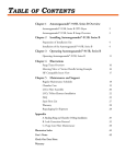
1
September 8, 1993
THE DYNAMIC ESTUARY MODEL
HYDRODYNAMICS PROGRAM, DYNHYD5
MODEL DOCUMENTATION AND USER
MANUAL
by
Robert B. Ambrose, Jr., P.E.
Tim A. Wool1
James L. Martin, Ph.D., P.E.1
Environmental Research Laboratory
Athens, Georgia 30613
1
AScI Corporation
Athens, Georgia 30605
ENVIRONMENTAL RESEARCH
LABORATORY
OFFICE OF RESEARCH AND
DEVELOPMENT
U.S. ENVIRONMENTAL PROTECTION
AGENCY
ATHENS, GEORGIA 30613
CONTENTS
CONTENTS . . . . . . . . . . . . . . . . . . . . . . . . . .
ii
FIGURES
. . . . . . . . . . . . . . . . . . . . . . . . . .
iv
TABLES . . . . . . . . . . . . . . . . . . . . . . . . . . .
v
1. INTRODUCTION TO DYNHYD5 . . . . . . . .
1.1 Overview of DYNHYD5 . . . . . . .
1.2 The Hydrodynamic Equations . . .
The Equation of Motion . . . .
The Equation of Continuity . .
1.3 The Model Network . . . . . . . .
1.4 Implementation of the Equations .
1.5 The Model Parameters . . . . . .
Junction Parameters . . . . . .
Channel Parameters . . . . . .
Inflow/Outflow Parameters . . .
Downstream Boundary Parameters
Wind Parameters
. . . . . . .
1.6 Application of the Model . . . .
1.7 Linkage to WASP5 . . . . . . . .
.
.
.
.
.
.
.
.
.
.
.
.
.
.
.
.
.
.
.
.
.
.
.
.
.
.
.
.
.
.
.
.
.
.
.
.
.
.
.
.
.
.
.
.
.
1
1
1
1
9
12
15
18
18
19
21
22
23
23
25
THE INPUT DATASET
2.1 Introduction . . . . . . . . . . . . . . . . .
2.2 DATA GROUP A: Simulation Control . . . . . . .
2.3 DATA GROUP B: Printout Control . . . . . . . .
2.4 DATA GROUP C: Hydraulic Summary . . . . . . .
2.5 DATA GROUP D: Junction Data. . . . . . . . . .
2.6 DATA GROUP E: Channel Data . . . . . . . . . .
2.7 DATA GROUP F: Inflow Data. . . . . . . . . . .
2.8 DATA GROUP G: Seaward Boundary Data. . . . . .
2.9 DATA GROUP H: Wind Data. . . . . . . . . . . .
2.10 DATA GROUP I: Precipitation/Evaporation Data .
2.11 DATA GROUP J: Variable Junction Geometry Data
2.12 DATA GROUP K: Variable Channel Geometry Data .
2.13 DATA GROUP L: WASP5 Junction to Segment Map .
2.14 DYNHYD5 OUTPUT . . . . . . . . . . . . . . . .
.
.
.
.
.
.
.
.
.
.
.
.
.
.
.
.
.
.
.
.
.
.
.
.
.
.
.
.
29
31
32
33
33
34
35
36
39
40
41
41
42
43
REFERENCES . . . . . . . . . . . . . . . . . . . . . . . . .
44
2.
ii
.
.
.
.
.
.
.
.
.
.
.
.
.
.
.
.
.
.
.
.
.
.
.
.
.
.
.
.
.
.
.
.
.
.
.
.
.
.
.
.
.
.
.
.
.
.
.
.
.
.
.
.
.
.
.
.
.
.
.
.
.
.
.
.
.
.
.
.
.
.
.
.
.
.
.
.
.
.
.
.
.
.
.
.
.
.
.
.
.
.
FIGURES
1.
2.
3.
4.
5.
6.
7.
8.
9.
10.
11.
12.
13.
14.
Gravitational Acceleration . . . . . . .
Frictional Acceleration . . . . . . . . .
Wind Acceleration Magnitude . . . . . . .
Wind Stress Direction . . . . . . . . . .
Wind Stress Vector Analysis . . . . . . .
Wind Stress Effects . . . . . . . . . . .
Equation of Continuity . . . . . . . . .
Model Network . . . . . . . . . . . . . .
Representation of the Model Network . . .
Definition Sketch for Junctions . . . . .
Defininion Sketch for Channels . . . . .
Inflow Time Function . . . . . . . . . .
Definition Sketch for Downstream Boundary
Link-Node Hydrodynamic Linkage . . . . .
iii
.
.
.
.
.
.
.
.
.
.
.
.
.
.
.
.
.
.
.
.
.
.
.
.
.
.
.
.
.
.
.
.
.
.
.
.
.
.
.
.
.
.
.
.
.
.
.
.
.
.
.
.
.
.
.
.
.
.
.
.
.
.
.
.
.
.
.
.
.
.
.
.
.
.
.
.
.
.
.
.
.
.
.
.
.
.
.
.
.
.
.
.
.
.
.
.
.
.
3
4
6
8
10
11
12
13
14
19
21
22
24
27
TABLES
1.
DYNHYD5 Display Variables . . . . . . . . . . . . . . .
iv
43
CHAPTER 1
INTRODUCTION TO DYNHYD5
1.1 OVERVIEW OF DYNHYD5
The WASP5 hydrodynamics model DYNHYD5 is an update of
DYNHYD4 (Ambrose, et al., 1988), which was an enhancement of the
Potomac Estuary hydrodynamic model DYNHYD2 (Roesch et al., 1979)
derived from the original Dynamic Estuary Model (Feigner and
Harris, 1970). DYNHYD5 solves the one-dimensional equations of
continuity and momentum for a branching or channel-junction
(link-node), computational network. Driven by variable upstream
flows and downstream heads, simulations typically proceed at 1to 5-minute intervals. The resulting unsteady hydrodynamics are
averaged over larger time intervals and stored for later use by
the water-quality program.
1.2 THE HYDRODYNAMIC EQUATIONS
The hydrodynamic model solves one-dimensional equations
describing the propagation of a long wave through a shallow water
system while conserving both momentum (energy) and volume (mass).
The equation of motion, based on the conservation of momentum,
predicts water velocities and flows. The equation of continuity,
based on the conservation of volume, predicts water heights
(heads) and volumes. This approach assumes that flow is
predominantly one-dimensional, that Coriolis and other
accelerations normal to the direction of flow are negligible,
that channels can be adequately represented by a constant top
width with a variable hydraulic depth (i.e., "rectangular"), that
the wave length is significantly greater than the depth, and that
bottom slopes are moderate. Although no strict criteria are
available for the latter two assumptions, most natural flow
conditions in large rivers and estuaries would be acceptable.
Dam-break situations could not be simulated with DYNHYD5, nor
could small mountain streams.
1.2.1 The Equation of Motion
The equation of motion is given by:
MU
MU
' &U
% a g,8 % a f % a w,8
Mt
Mx
(1)
1
where:
MU
Mt
=
the local inertia term, or the velocity rate
of change with respect to time, m/sec2
=
the Bernoulli acceleration, or the rate of
momentum change by mass transfer; also
defined as the convective inertia term from
Newton's second law, m/sec2
ag,8
=
gravitational acceleration along the 8 axis
of the channel, m/sec2
af
=
frictional acceleration, m/sec2
aw,8
=
wind stress acceleration along axis of
channel, m/sec2
x
=
distance along axis of channel, m
t
=
time, sec
U
=
velocity along the axis of channel, m/sec
8
=
longitudinal axis
U
MU
Mx
2
Gravitational acceleration is driven by the slope of the water
surface. Referring to Figure 1, the acceleration along the
longitudinal axis is
G RAVITY
Accelera tion of G ra vity = g
a
g ,l
S=
a
H
X
g ,l
S
g
a g , l= -g
s inS
-g
S
a g , l= -g
H
X
Figure 1
Gravitational Acceleration
a g,8 ' &g sin S
(2)
where:
g
=
acceleration of gravity = 9.81 m/sec2
S
=
water surface slope, m/m.
Because the value of S is small, sin S can be replaced by S.
Expressing S as the change of water surface elevation with
longitudinal distance gives:
3
a g,8 ' &g
MH
Mx
where:
H
=
water surface elevation, or head (height above an
arbitrary datum), m
The frictional acceleration term can be expressed using the
Manning equation for steady uniform flow:
U '
R 2/3 M H 1/2
n
Mx
(4)
where:
R
=
hydraulic radius (approximately equal to the depth
for wide channels), m
n
=
Manning roughness coefficient (usually between
0.01 and 0.10), sec/m1/3
=
the energy gradient, m/m
MH
Mx
4
Referring to Figure 2, gravitational acceleration balances
frictional resistance for steady flow conditions, such that:
FRICTIONAL RESISTANCE
For Stea dy U niform
M a nning
:
Equ a tion
a
a
f
Flow
R 2/3
U=
H
X
n
a
g
f
= a
g
= -g
H
X
Over Short Tim e Interva l
a
Figure 2
af ' g
f
=
gn
R
2
U
4/3
U
Frictional Acceleration
MH
Mx
(5)
Unfortunately, tidally influenced estuaries rarely experience
truly steady flow. Over short time intervals, however, flow may
be considered steady and uniform. Consequently, the energy
gradient from equation 4 can be substituted into equation 5 to
give:
5
a f ' 1&
g n2
*U*U
R 4/3
(6)
where U2 has been replaced by U times the absolute value of U so
friction will always oppose the direction of flow.
Referring to Figure 3, one sees that the magnitude of the
wind acceleration term can be derived from the shear stress
equation at the air-water boundary:
W IND STRESS
A. M a g nitu de
W ind
Speed
10 M eters
Fw
w
A
s
V
R
a
w = Cd
F
a
w
C
Figure 3
a
d
=
=
w =
W
2
As
w
F
w = w
a
a
=
w
w
w
(V w
C
d
R
)w
a
W 2
w
0 .0 0 26
1.165 x 10 -3
Wind acceleration magnitude
Jw ' C d Da W 2
(7)
where:
6
JW
=
the boundary shear stress, kg/m-sec2
Cd
=
the drag coefficient (assumed to retain constant
value of 0.0026), unitless
Da
=
the density of air, kg/m3
Da
=
the wind speed (relative to the moving water
surface) measured at a height of 10 meters, m/sec
The force exerted on the water surface, As, is:
Fw ' Jw As
(8)
Substituting equation 7 into equation 8 gives:
Fw ' C d As Da W 2
(9)
This force causes a volume of water Vw to accelerate in the wind
direction:
aw '
Fw
V w Dw
(10)
The hydraulic radius, R, is the channel cross sectional area
divided by the wetted perimeter. In natural channels where the
width is much larger than the depth, the wetted perimeter is
almost equal to the width. Over a channel length, then, the
average hydraulic radius is approximately equal to the volume of
water divided by the surface area:
R ' V w /A s
(11)
where:
As
=
surface area, m2
Vw
=
water volume, m3
Substituting equations 9 and 11 into equation 10 gives the
7
following equation for the wind acceleration term:
aw '
C d Da 2
W
R Dw
(12)
where:
Dw
=
density of water, kg/m3
Da/Dw
=
1.165 x 10⁻³
Referring to Figure 4, the component of acceleration along
the channel axis is:
W IND STRESS
B: Direction
W
a
M a g nitu de = W
w,l
Direction =
a
a
w,n
N
W
Cha nnelDirection =
W ind Direction =
Rela tive Ang le =
a
Figure 4
w,l
=
.
a
w
Wind stress direction
8
cos
w
a w,8 '
Cd Da 2
W cos R
R Dw
(13)
where:
R
=
the angle between the channel direction and the
wind direction (relative to the moving water
surface)
Both the water and wind have velocity components that
contain both magnitude and direction. If the water is moving
with a velocity U, then the wind vector W experienced at the
water surface is given by the following (see Figure 4):
W ' W obs & U
(14)
where:
W obs
=
the wind vector observed at a stationary location,
10 meters above the water surface (magnitude =
Wobs, direction = M)
=
the current vector (magnitude = U, direction = 1),
m/sec
U
Therefore,
W
is the relative wind vector with magnitude W, and
the effective wind angle relative to the channel axis is
R ' " & 2
(15)
9
W IND STRESS
From VectorAna lys is
Vector
X
U
W
Y
U s in
W
OBS
W
W
W
2
=
U
OBS
2
+
U cos
s in
OBS
W OBS
s in
W
2
-
2
OBS
W
=
ta n
-1
W
=
Figure 5
W
- U sin
OBS
OBS
s in
cos
U
W OBS
- U sin
- U cos
-
Wind stress vector analysis
10
OBS
cos
cos
cos
- U cos
(
-
)
Given observations of Wobs, U, M, and 1, the magnitude and
direction of W can be calculated using vector analysis (Figure
5):
W 2 ' U 2 % W obs 2 & 2 U W obs cos(2 & N)
" ' tan &1
W obs sin N & U sin 2
W obs cos N & U cos 2
(16)
(17)
Wind acceleration can either enhance or oppose stream flow,
depending on the relative direction of the wind Q. For wind
blowing normal to the channel axis, cos Q = 0, and there is no
acceleration along the axis. For wind blowing along the axis in
a positive direction, cos Q = +1. Positive flow in the channel
will be enhanced, and negative flow will be opposed. Conversely,
for wind blowing along the axis in a negative direction, cos Q =
-1. Positive flow in the channel will be opposed, and negative
flow will be enhanced (refer to Figure 6).
11
W IND STRESS EFFECT
W ind a nd Strea m
Directions
W
cos
U
W
U
W
U
W
U
W
U
Figure 6
Effect
90 o
0
None
0 o
1
Enha nced
Accelera tion
180 o
-1
Oppps ed
180 o
-1
Oppos ed
1
Enha nced
0 o
Wind stress effects
1.2.2 The Equation of Continuity
The equation of continuity is given by:
MA
MQ
' &
Mt
Mx
(18)
where:
A
=
cross-sectional area, m2
Q
=
flow, m3/sec
For rectangular channels of constant width B (refer to
Figure 7):
12
MH
1 MQ
' &
Mt
B Mx
(19)
EQUATION OF CONTINUITY
A
Q
=-
X
t
RECTANG U LAR CHANNELS
(Q +
B
Q)
A
X
H
=-
t
Figure 7
Q
1
Q
B
X
Ra te of
Ra te of
W a ter Su rfa ce
Volu m e
Eleva tionCha ng e
Cha ng e
Equation of continuity
where:
B
=
width, m
H
=
water surface elevation (head), m
13
MH
Mt
1 MQ
B Mx
1.3
=
rate of water surface elevational change with
respect to time, m/sec
=
rate of water volume change with respect to
distance per unit width, m/sec
THE MODEL NETWORK
Equations 1 and 19 form the basis of the hydrodynamic model
DYNHYD5. Their solution gives velocities (U) and heads (H)
throughout the water body over the duration of the simulation.
Because closed-form analytical solutions are unavailable, the
solution of equations 1 and 19 requires numerical integration on
a computational network, where values of U and H are calculated
at discrete points in space and time. A flexible,
computationally efficient type of network has been developed for
these equations (Feigner and Harris, 1970). The "link-node"
network solves the equations of motion and continuity at
alternating grid points.
At each time step, the equation of
motion is solved at the links, giving velocities for mass
transport calculations, and the equation of continuity is solved
at the nodes, giving heads for pollutant concentration
calculations (Figure 8).
14
M ODEL NETW ORK
LINK S (CHANNELS) - CONVEY W ATER
NODES (J U NCTIONS) - STORE W ATER
AT EACH TIM E STEP:
EQ U ATION
OF
M OTION
EQ U ATION
OF CONTINU ITY
Figure 8
LINK S
VELOCITY
FLOW S
M ASS
TRANSPORT
NODES
HEADS
VOLU M ES
POLLU TANT
CONCENTRATION
Model network
15
Figure 9
Representation of the model network.
16
A physical interpretation of this computational network can
be developed by picturing the links as channels conveying water
and the nodes as junctions storing water (Figure 9). Each
junction is a volumetric unit that acts as a receptacle for the
water transported through its connecting channels. Taken
together, the junctions account for all the water volume in the
river or estuary. Parameters influencing the storage of water
are defined within this junction network. Each channel is an
idealized rectangular conveyor that transports water between two
junctions, whose midpoints are at each end. Taken together, the
channels account for all the water movement in the river or
17
estuary. Parameters influencing the motion of water are defined
within this channel network. The link-node computational
network, then, can be viewed as the overlapping of two closely
related physical networks of channels and junctions.
Junctions are equivalent to segments in the water quality
model, whereas channels correspond to segment interfaces.
Channel flows are used to calculate mass transport between
segments in the water quality model. Junction volumes are used
to calculate pollutant concentrations within water quality
segments.
Link-node networks can treat fairly complex branching flow
patterns and irregular shorelines with acceptable accuracy for
many studies. They cannot handle stratified water bodies, small
streams, or rivers with a large bottom slope. Link-node networks
can be set up for wide, shallow water bodies if primary flow
directions are well defined. Results of these simulations should
be considered descriptive only.
1.4
IMPLEMENTATION OF THE EQUATIONS
To apply differential equations 1 and 19 to a link-node
computational network, they must first be written in a finite
difference form. The equation of motion becomes:
U it & U i
U
) Hi
g n i2
' Ui ) i & g
&
U i*U i*
)t
)x i
) xi
R i 4/3
%
C d Da 2
W cos R i
R i Dw i
(20)
(21)
where:
U it
=
the velocity in channel i at time t,
m/sec
)x i
=
the channel length, m
18
)t
i
=
the time step, sec
=
channel or link number
=
velocity gradient in channel i with respect
to distance, sec-1
=
water surface gradient in channel i with
respect to distance, m/m
)U i
)x i
)H i
)x i
All values on the right hand side of equation 20 are
referenced to the previous time step (t-)t).
The water surface gradient, )Hi/)xi, can be computed from
the junction heads at either end of the channel. The velocity
gradient, however, can not be computed directly from upstream and
downstream channel velocities because of possible branching in
the network. If branching does occur, there would be several
upstream and downstream channels, and any computed velocity
gradient would be ambiguous. An expression for the velocity
gradient within a channel can be derived by applying the
continuity equation 18 to the channel and substituting U A for Q:
MA
MQ
MA
MU
' &
' &U
& A
Mt
Mx
Mx
Mx
(22)
Rearranging terms:
MU
1 MA
U MA
' &
&
Mx
A Mt
A Mx
(23)
Writing this in finite difference form and substituting B R
for A and B )H for M A gives the following expression for the
velocity gradient:
19
) Ui
U )H i
1 ) Hi
' &
& i
R i )t
) xi
R i )x i
(24)
The term )Hi/)t is computed as the average water surface
elevational change between the junctions at each end of channel i
during time step t. Substituting equation 1.2.23 into 1.2.20 and
rearranging gives the explicit finite difference equation of
motion applied to each channel i:
U it
U )H i
' Ui % ) t [ i
%
R i )t
&
g n i2
Ri
4/3
U i * Ui * %
U i2
&g
Ri
) Hi
) xi
Cd Da 2
W cos R i]
Ri Dw i
(25)
(26)
Writing the equation of continuity (19) in finite difference form
gives:
H jt & H j
)Q j
' &
)t
B j )x j
(27)
where:
j
=
junction or node number
The numerator )Qj is given by the summation of all flows
entering and leaving the junction. The denominator Bj )xj can be
expressed directly as the surface area Ajs of the junction.
Substituting these identities into equation 25 and rearranging
gives the explicit finite difference equation of continuity
applied to each junction j:
H jt
' H j & )t
' Q ij
i
(28)
A js
At this point, one equation for each channel and each
20
junction in the computational network exists. Given input
parameters describing the network configuration and geometry,
initial values for channel velocities and junction heads,
boundary conditions for downstream heads, and forcing functions
for freshwater inflow and wind stress, equations 24 and 26 are
solved using a modified Runge-Kutta procedure. The solution
proceeds in eight steps, which are repeated throughout the
simulation:
1.5
1)
For the middle of the next time interval (i.e., for
time t + )t/2), the mean velocity for each channel is
predicted using the channel velocities and
cross-sectional areas and the junction heads at the
beginning of the current time interval.
2)
For t + )t/2, the flow in each channel is computed
using the velocity obtained in step (1) and the
cross-sectional area at the beginning of the current
interval.
3)
At t + )t/2, the head at each junction is computed
using the flows derived in step (2).
4)
At t + )t/2, the cross-sectional area of each channel
is computed using the heads computed in step (3).
5)
The mean velocity for each channel is predicted for the
full time step (t + )t) using the velocities,
cross-sectional areas, and junction heads computed for
t + )t/2 in steps (1), (3), and (4).
6)
The flow in each channel for t + )t is computed using
the velocity for the full time step (computed in step
5) and the cross-sectional area computed for t + )t/2
in step 4).
7)
The head at each junction after t + )t is computed
using the full step flow computed in step (6).
8)
The cross-sectional area of each channel after a full
time step is computed using the full step heads from
step (7).
9)
Steps (1) through (8) are repeated for the specified
number of time intervals.
THE MODEL PARAMETERS
21
This section summarizes the input parameters that must be
specified in order to solve the equations of motion and
continuity. Other parameters calculated by the model also are
discussed.
1.5.1
Junction Parameters
The input parameters associated with junctions are initial
surface elevation (head), surface area, and bottom elevation.
Volumes and mean depths are calculated internally. A definition
sketch is given in Figure 10.
J U NCTION
SURFACE AREA
SURFACE SLOPE
HEAD
DATU M
DEPTH
BOTTOM
ELEVATION
(AVERAG E)
Figure 10
Definition sketch for junctions.
Surface elevation or head, m--Junction heads represent the
mean elevation of the water surface above or below an arbitrary
horizontal datum. The datum is usually the mean local sea level.
If initial surface elevations are not input, they will be
calculated from bottom elevation and depth.
Surface area, m2--Except when branching or looping occurs
22
(i.e., when more than two channels enter a junction), the surface
area of a junction is equated to one-half of the sum of the
surface areas of the two channels entering the junction. When
branching or looping does occur, the junction surface areas can
be determined by laying out a polygon network using the Thiessen
Polygon method, as in Figure 11. Since the polygons are normally
irregular, a planimeter must be used to obtain the surface areas.
Bottom elevation, m--The mean elevation of the junction
bottom above or below the datum is defined as the bottom
elevation. If initial surface elevations are specified, bottom
elevations will be calculated internally by subtracting the mean
depth from the mean head.
Volume, m3--Initial junction volumes are computed internally
by multiplying the junction surface area by the mean depth of the
channels (weighted by their cross-sectional area) entering the
junction. Junction volumes are updated throughout the simulation
by adding the product of the surface area and the change in
surface elevation to the initial volume.
1.5.2 Channel Parameters
The input parameters associated with channels are length,
width, hydraulic radius or depth, channel orientation, initial
velocity, and Manning's roughness coefficient. A definition
sketch is given in Figure 11.
Length, m--The channel length is the distance between the
midpoints of the two junctions it connects. Channels must be
rectangular and should be oriented so as to minimize the depth
variation as well as reflect the location and position of the
actual prototype channels. The channel length is generally
dependent on a computational stability criteria given by:
L i $ ( g yi ± U i) ) t
(29)
where:
Li
=
length of channel i, m
yi
=
mean depth of channel i, m
Ui
=
velocity in channel i, m/sec
)t
=
computational time step
23
g
=
acceleration of gravity
Width, m--There is no apparent limit on the width of a
channel. If a channel is too wide in relation to its length,
however, the mean velocity predicted may mask important velocity
patterns occurring on a more local scale. For well defined
channels, the network channel widths are equated to the average
bank to bank width.
LENG TH
VELOCITY
PROFILE
TOP
VIEW
W IDTH
AVERAG E
VELOCITY
VELOCITY
PROFILE
AVERAG E
DEPTH
SIDE
VIEW
HYDRAU LIC
RADIU S
W IDTH
CROSS
SECTIONAL
AVERAG E
DEPTH
AREA
PLAN
VIEW
SIDE SLOPE
1
2
CHANNEL
ORIENTATION
1
2
Figure 11
Definition sketch for channels
Cross-sectional area, m2--The cross-sectional area of a
channel is equal to the product of the channel width and depth.
Depth, however, is a channel parameter that must be defined with
respect to junction head or water surface elevation (since both
vary similarly with time). Initial values of width and depth
based on the initial junction heads and the initial
cross-sectional areas are computed internally. As the junction
heads vary, the channel cross-sectional areas are adjusted
accordingly.
Roughness coefficients, sec/m1/3--Channels are assigned
24
"typical" Manning Roughness coefficients. The value of this
coefficient should usually lie between 0.01 and 0.08. Because
this parameter cannot be measured, it serves as a "knob" for the
calibration of the model.
Velocity, m/sec--An initial estimate of the mean channel
velocity is required. Although any value may be assigned, the
computational time required for convergence to an accurate
solution will depend on how close the initial estimate is to the
true value. Convergence is usually rather quick.
Hydraulic radius, m--Previous applications of DYNHYD have
used channels whose widths are greater than ten times the channel
depth. Consequently, the hydraulic radius is usually assumed to
be equal to the mean channel depth.
Channel orientation, degrees--The channel orientation is the
direction of the channel axis measured from true north. The axis
is assumed to point from lower junction number to higher junction
number, which by convention, is the direction of positive flow
(i.e.: upstream to downstream).
1.5.3 Inflow/Outflow Parameters
25
Inflows and outflows can be specified as constant or time
variable. Inflows are represented by negative flows(i.e.: to
introduce a flow across a boundary into the network it must be
negative); outflows are represented by positive flows. For each
time-variable inflow, a piecewise linear function of flow versus
Flow
Tim e
Piecew is e Linea r Fu nction
Tim e
Da y
Figure 12
Flow
m 3 /s ec
Hou r:M in
1
0 9 30
30 .
2
10 0 0
40 .
3
13 0 0
80 .
4
12 30
70 .
5
12 0 0
75.
6
18 30
20 .
7
0 9 30
30 .
Inflow time function.
time is specified, as in Figure 12. If the simulation extends
beyond the last specified flow, the flow assumes a constant
inflow equal to the last specified flow.
1.5.4 Downstream Boundary Parameters
26
The downstream boundaries can be defined by either
specifying outflows or surface elevations (tidal function).
Surface elevations at each downstream boundary can be specified
by an average tidal function or by a variable tidal function. A
definition sketch is provided in Figure 13.
For some simulations, the average tidal variability will
produce accurate predictions of tidal transport. Tidal heights
(referenced to the model datum) are specified at equally spaced
intervals throughout the average tidal cycle.
Normally,
30-minute intervals will suffice. These data can be obtained
from tidal stage recorders located at or near the model boundary.
If no recorders are available, the predictions presented in the
U.S. Coast and Geodetic Survey Tide Tables can be used.
DYNHYD5 reduces the height versus time data to the following
function using the subroutine REGAN.
y ' A 1 % A 2 sin ( T t) % A 3 sin ( 2T t)% A 4 sin ( 3T t)
% A 5 cos ( Tt) % A 6 cos ( 2 Tt) %A 7 cos (3 Tt)
(30)
(31)
where:
y
=
tidal elevation above or below the model datum, m
Ai
=
regression coefficients, m
T
=
2B/tidal period, hr-1
t
=
time, hr
27
Figure 13
Definition sketch of downstream boundary.
28
If the regression coefficients Ai are known, they can be
specified instead of the height versus time data. All seven of
the coefficients must be specified in the above order. The
average tidal function is repeated throughout the simulation.
If data are available, variable tidal patterns may be
simulated by specifying the high and low tidal heights versus
time for multiple tidal cycles. In this case, the subroutine
RUNKUT will interpolate with a sinusoidal curve between the data
points. If simulation extends beyond the specified tidal cycles,
the sequence will repeat. To insure proper repetition, an odd
number of data points must be specified with the last data point
equal to the first.
1.5.5 Wind Parameters
The input parameters associated with wind acceleration are
wind speed, wind direction, channel orientation, and channel
hydraulic radius. The last two were discussed as channel
parameters. A definition sketch was provided in Figure 11 and 4.
Wind speed (m/sec) and direction (degrees from true north)
29
are measured at a point 10 meters above the water surface. This
wind is to be representative for the entire water body. Values
of wind speed and direction can vary with time. Piecewise linear
functions of wind speed and direction versus time are specified
(similar to Figure 12 for flow). If the simulation extends
beyond the last specified wind, the piecewise linear functions
are repeated.
1.6
APPLICATION OF THE MODEL
A great deal of flexibility is allowed in laying out the
network of interconnected channels and junctions that represent a
system, but there are several guidelines for making the best
representation. First, both hydraulic and quality factors should
be considered when selecting boundary conditions. Ideally, the
downstream boundary should extend to a flow gage, a dam, or the
ocean. The upstream boundary should extend to or beyond the
limits of any backwater or tidal effects on the inflowing
streams. Such a network eliminates problems associated with
dynamic boundary conditions, such as changing salinity or other
quality conditions, which could be present if an inland point
were chosen for the seaward boundary. Other considerations
influencing boundary locations and the size of network elements
include the location of specific points where quality predictions
are required, the location of existing or planned sampling
stations (and the availability of data for verification), the
degree of network detail desired, and the computer time available
for solution.
In most applications of DYNHYD5, Manning's roughness
coefficient (n) will be the primary calibration parameter. The
value of n can be highly variable, depending on such factors as
bed roughness, vegetation, channel irregularities in
cross-section or shape, obstructions, and depth. Values of n can
potentially vary from less than 0.01 to greater than 0.08. For
the larger rivers, reservoirs, and estuaries to which DYNHYD5 can
be applied, however, values will usually fall between 0.01 and
0.04. Deeper, straighter reaches have lower roughness
coefficients. In general, the value of n increases upstream as
channels become more constricted and shallow.
When calibrating DYNHYD5, changing the value of n in one
channel affects both upstream and downstream channels.
Increasing n causes more energy to be dissipated in that channel.
As a result, the height of a tidal or flood wave will decrease
and the time of travel through the channel will increase.
Lowering n decreases the resistance to flow, resulting in a
higher tidal or flood wave and a shorter time of travel.
30
1.7
LINKAGE TO WASP5
The hydrodynamic results generated by a DYNHYD5 simulation
can be stored for use by WASP5 water quality simulations using an
external formatted file containing segment volumes at the
beginning of each time step and average segment interfacial flows
during each time step. WASP5 uses the interfacial flows to
calculate mass transport and the volumes to calculate constituent
concentrations. Segment depths and velocities may also be
contained in the hydrodynamic file for use in calculating
reaeration and volatilization rates.
When linking DYNHYD5 to WASP5, both the networks and the
time steps must be compatible (though not identical). This
linkage is accomplished through an external file chosen by the
user at simulation time. The first step in the hydrodynamic
linkage is to develop a hydrodynamic calculational network that
is compatible with the WASP5 network. An example is given in
Figure 14. Note that each WASP5 segment corresponds exactly to a
hydrodynamic volume element, or node. Each WASP5 segment
interface corresponds exactly to a hydrodynamic link, denoted in
the figure with a connecting line.
31
Figure 14
Link-node hydrodynamic linkage.
32
To link with WASP5 the user must specify which DYNHYD5
junctions will be linked to WASP5 segments. It is no longer
necessary to link junctions and segments one to one; the user has
the capability of linking a section of the hydrodynamic
simulation. It is important to insure the "windowed" section is
contiguous. When linking boundary junctions to WASP5 they are
designated as 0 segment (the WASP convention for boundaries).
You must provide the linkage map for WASP5 in the DYNHYD5
dataset.
WASP5 may have additional segments not represented by
junctions. For example, WASP5 benthic segments will have no
corresponding junctions. Junction numbering need not correspond
to segment numbering. Junction to segment mapping is specified
in the DYNHYD5 input data set. The WASP5 time step must be an
even multiple of the DYNHYD5 time step. The ratio of time steps
must be specified in the DYNHYD5 input data set as parameter
NODYN. Typical ratios are between 6 and 30. DYNHYD5 averages
each channel flow over NODYN hydrodynamic time steps, and stores
this average value for use at the corresponding WASP5 segment
interface. DYNHYD5 stores each junction volume at the end of
NODYN time steps for use at the corresponding WASP5 segment.
This averaging and storage process continues for the entire
hydrodynamic simulation. WASP5 will use these flows and volumes,
repeating the sequence if the water quality simulation is longer
than the hydrodynamic simulation. If the volumes of the segments
differ by more then 5% from the beginning to the end of the
hydrodynamic summary file, the WASP5 simulation will not continue
beyond the hydrodynamic simulation.
It is important to note that the hydrodynamic model has
33
additional nodes outside of the WASP5 network. These additional
nodes correspond to WASP5 boundaries, denoted by nominal segment
number "0." These extra hydrodynamic nodes are necessary because
while flows are calculated only within the hydrodynamic network,
WASP5 requires boundary flows from outside its network.
To implement the hydrodynamic linkage, the user must specify
flow option 3 in the input dataset. If IQOPT is set to 3, a menu
of previously prepared hydrodynamic files (*.HYD) is presented.
Following the choice of a proper file, the simulation time step
will be reset by the hydrodynamic file. The time steps read in
Data Group A will be ignored. Similarly, water column segment
volumes will be read from the hydrodynamic file. The user must
nevertheless enter a time step and volumes for each segment in
the usual location. During the simulation, flows and volumes are
read every time step.
The contents and format of the hydrodynamic file are
detailed in Part B, The WASP5 Input Dataset, Section 5.2.
34
CHAPTER 2
THE DYNHYD5 INPUT DATASET
2.1
INTRODUCTION
This section describes the input required to run the DYNHYD5
hydrodynamics program. This information is provided to the user
who elects not to use the preprocessor program PREDYN. PREDYN
allows you to create/modify datasets with relative ease and has
complete online help. The user should be cautioned about
potential changes to the dataset or manual that may accompany
version updates of the software. The printed manual may become
dated as enhancements are made or errors are identified and
corrected. Please download the latest manual accompanying the
current version of DYNHYD5.
To arrange the input into a logical format, DYNHYD5 data are
divided into 12 groups, A through L:
A
-
Simulation Control
B
-
Printout Control
C
-
Hydraulic Summary
D
-
Junction Data
E
-
Channel Data
F
-
Inflow Data
G
-
Seaward Boundary Data
H
-
Wind Data
I
-
Precipitation/Evaporation Data
J
-
Variable Junction Geometry Data
K
-
Variable Channel Geometry Data
L
-
WASP5 Junction to Segment Map
The following is a brief explanation of each data group.
Data Group A consists of preliminary data, such as network
35
parameters (number of channels, number of junctions), simulation
time step, and the beginning and ending day of simulation.
Data Group B allows the user to specify printing options.
Data Group C is responsible for the storage of flows and
volumes. The stored file created by this data group can be used
as an input data set for the water quality model.
Data Group D describes the model network and initial
conditions at each junction.
Data Group E describes the model network and initial
conditions at each channel.
Data Group F lists all inflows into the model system.
may be constant or variable. Inflows are considered to be
negative, and outflows are positive.
Flows
Data Group G describes the seaward boundaries. The maximum
number of seaward boundaries has been set to five, but can be
respecified by the user. There are two types of tidal inputs:
average tide, and variable tide. The average tide is a smooth,
repetitive curve that fits the equation:
Head ' A 1 % A 2 sin(T t) A 3 sin(2 T t) A 4 sin(3T t)
A 5 cos(Tt) A 6 cos(2 Tt) A 7 cos(3 Tt)
(32)
(33)
The variable tide is a half sine wave that has highs and lows as
specified by the data set.
Data Group G has three options for defining the tidal cycle.
Option 1, the user specifies the coefficients in equation 32 for
an average tide. Option 2, the user specifies data and the model
calculates the coefficients in equation 32 which define the
average tide. Option 3, the user specifies the highs and lows of
a variable tide and the model fits a half sine curve through the
points.
Data Group H lists wind speeds and directions.
Data Group I lists precipitation and evaporation into or out
of designated junctions.
36
Data Group J gives the variation in surface area with
changes in head for designated junctions. The default is zero,
or constant surface area.
Data Group K gives the variation in width with changes in
head for designated channels. The default is zero, or constant
channel width.
Data Group L gives information mapping the DYNHYD model
network onto a WASP model network. This information is read only
if a hydraulic summary file is being prepared (as specified in
Data Group C).
2.2
DATA GROUP A:
SIMULATION CONTROL
Record 1--Title of Simulation (A80)
ALPHA(J)
=
alphanumeric characters to identify the
system, date and run number. (20A4)
Record 2--Description of Simulation (A80)
ALPHA(J)
=
alphanumeric characters to identify the
system, date and run number. (20A4)
Record 3--Data Group Identification (A80)
HEADER
=
alphanumeric characters to identify the data
group, "PROGRAM CONTROL DATA." (20A4)
Record 4--Simulation Control Data
(3I5, F5.0, I5, F5.0, F3.0 F2.0, F5.0, F3.0 F2.0)
NJ
=
number of junctions in the model network.
(I5)
NC
=
number of channels in the model network. (I5)
NCYC
=
total number of time steps for execution
(number of cycles). If equal to zero, the
model will compute NCYC internally (cycles).
(I5)
DELT
=
time interval used in execution (sec). Note
that it is important that the time step meet
the Courant condition, that is, it should be
37
less than the shortest channel length divided
by the wave celerity (see equation 29 in
section 1.5.2 above). (F5.0)
ICRD
=
file containing the initial conditions for
junctions and channels. If equal to 0 or 5,
data set is read. If equal to 8, a file 8,
previously created by subroutine RESTART, is
read. (I5)
ZDAY
=
beginning day of simulation (day).
(F5.0)
ZHR
=
beginning hour of simulation (hr).
(F3.0)
ZMIN
=
beginning minute of simulation (min). (F2.0)
EDAY
=
ending day of simulation (day).
(F5.0)
EHR
=
ending hour of simulation (hr).
(F3.0)
EMIN
=
ending minute of simulation (min).
(F2.0)
ALPHA(1), ALPHA(2), and HEADER assist the user in
maintaining a log of computer simulations, but are not actually
used by the DYNHYD5 program.
Each record in Data Group A is input once; therefore, Data
Group A consists of 4 lines of data. Data Group B starts on the
5th line (no blank line).
2.3
DATA GROUP B: PRINTOUT CONTROL
Record 1--Data Group Identification (20A4)
HEADER
=
alphanumeric characters to identify the data
group, "PRINTOUT CONTROL DATA." (20A4)
Record 2--Output Control Information (2F10.0, I5)
FPRINT
=
time for printout to begin (hr).
PINTVL
NOPRT
=
=
time interval between printouts (hr). (F10.0)
number of junctions for which printouts
(results) are desired, can be 1 through NJ.
(I5)
Record 3--List of Junctions (15I5)
38
(F10.0)
JPRT(I)
=
junction number for results to be printed.
(I5)
There will be NOPRT entries in Record 3 (I = 1 to NOPRT).
Records 1 and 2 are entered once. Record 3 may contain
several lines depending upon NOPRT. One line may contain up to
16 entries. Therefore, if NOPRT is equal to 1-16, then Record 3
will consist of 1 line. If NOPRT is equal to 17-32, then Record
3 will consist of 2 lines, etc. The total number of lines for
Data Group B equals 2 + (1 + INT((NOPRT-1)/16))).
2.4
DATA GROUP C: HYDRAULIC SUMMARY
Record 1--Data Group Identification (20A4)
HEADER
=
alphanumeric characters to identify the data
group "Summary Control Data." (A4)
Record 2--Summary Control Data (I5, F5.0, F3.0, F2.0, 2F5.0)
SUMRY
=
option number that controls how the
hydrodynamic scratch file (file 2) is
processed to create a permanent summary file
(file 4) for the water quality model to read.
If equal to zero, then no summary file will
be created. If equal to 1, a formatted file
will be created. (I5)
TDAY
=
day to begin storing parameters to file
(day). (5.0)
THR
=
hour to begin storing parameters to file
(hr). (F3.0)
TMIN
=
minute to begin storing parameters to file
(min). (F2.0)
DTDUMP
=
time interval for storing intermediate
results in scratch file; usually 12.5, 24.0,
or 25.0 hours (hr). (F5.0)
NODYN
=
number of hydraulic time steps per quality
time steps desired. (F5.0)
INTSCR
=
frequency with which to store hydraulic data
on scratch file, measured in hydraulic time
steps. (f5.0)
39
Records 1 and 2 are entered once.
consists of two lines.
2.5
Therefore, Data Group C
DATA GROUP D: JUNCTION DATA
Record 1--Data Group Identification (20A4)
HEADER
=
alphanumeric characters to identify the data
group, "JUNCTION DATA." (20A4)
Record 2-- Junction Data (I5, 3F10.0, 6I5)
JJ
=
junction number.
Y(J)
=
initial head (or surface elevation) in
reference to a horizontal model datum, at
junction JJ (m). (F10.0)
SURF(J)
=
surface area at junction JJ (m2).
BELEV(J)
=
bottom elevation above (or below) the
horizontal datum plane (usually taken to be
mean sea level)(m). (F10.0)
=
channel number entering junction JJ. Maximum
number of channels entering any one junction
is six (I = 1 - 6). Start list with lowest
channel number. (I5)
NCHAN(J,I)
(I5)
(F10.0)
Record 1 is entered once in Data Group D. Record 2 is
entered NJ times (NJ = number of junctions). One line is used
for each junction. Therefore, Data Group D consists of 1 + NJ
lines.
2.6
DATA GROUP E:
CHANNEL DATA
Record 1--Data Group Identification (20A4)
HEADER
=
alphanumeric characters to identify the data
group, "CHANNEL DATA." (20A4)
Record 2-- Channel Data (I5, 6F10.0, 2I5)
NN
=
channel number.
CLEN(N)
=
length of channel NN (m).
40
(I5)
(F10.0)
B(N)
=
width of channel NN (m).
R(N)
=
hydraulic radius or depth of channel NN (m).
(F10.0)
CDIR(N)
=
channel direction, or angle in degrees
measured from true north. The channel
direction points in the direction of positive
flow, from the higher junction number to the
lower junction number (degrees).(F10.0)
CN(N)
=
Manning roughness coefficient for channel NN
(sec. m-1/3). Ranges from 0.01 to 0.08.
(F10.0)
V(N)
=
the initial mean velocity in channel NN,
m/sec. (F10.0)
NJUNC(N,1)
=
the connecting junction at the lower end of
channel NN. (I5)
NJUNC(N,2)
=
the connecting junction at the higher end of
channel NN. (I5)
A channel may only connect two junctions.
NJUNC(N,1) and NJUNC(N,2) exists.
(F10.0)
Therefore, only
Record 1 is entered only once in Data Group E. Record 2 is
entered NC times (NC = number of channels). One line is used for
each channel. Therefore, Data Group E consists of 1 + NC lines.
2.7
DATA GROUP F:
INFLOW DATA
Record 1--Data Group Identification (20A4)
HEADER
=
alphanumeric characters to identify the data
group and type of inflows, "CONSTANT INFLOW
DATA." (20A4)
Record 2--Constant Inflow Number (I5)
NCFLOW
=
the number of constant inflows that will be
read. (I5)
If NCFLOW = 0, skip to Record 4.
Record 3--Constant Inflow Data (I10, F10.0)
41
JRCF(I)
=
junction that will be receiving the following
inflow. (I10)
CFLOW(I)
=
the value of the constant inflow into
junction JRCF(I) (m3/sec). Value will be
negative for inflow, positive for outflow.
(F10.0)
Record 4--Data Group Identification 20A4)
HEADER
=
alphanumeric characters to identify the type
of inflows, "VARIABLE INFLOW DATA." (20A4)
Record 5--Variable Inflow Number (I5)
NVFLOW
=
the number of variable inflows that will be
read. (I5)
If NVFLOW = 0, skip to Data Group G.
Records 6 and 7 are repeated as a unit NVFLOW times.
Record 6--Variable Inflow Breaks (2I10)
JRVF(I)
=
junction that will be receiving the following
variable inflows. (I10)
NINCR(I)
=
number of data points (breaks) for variable
inflow into junction JRVF(I). (I10)
Record 7--Variable Inflow Data (4(F5.0, F3.0, F2.0, F10.0))
DAY(K)
=
day of VFLOW(I,K) (day).
(F5.0)
HR(K)
=
hour of VFLOW(I,K) (hr).
(F3.0)
MIN(K)
=
minute of VFLOW(I,K) (min).
VFLOW(I,K)
=
value of the variable flow corresponding to
DAY(K), HR(K), and MIN(K) (m3/sec). Value
will be negative for inflow, positive for
outflow. (F10.0)
(F2.0)
Records 1 and 2 are entered once in Data Group F. Record 3
is entered NCFLOW times with one junction number and one flow per
line. Records 4 and 5 are entered once in Data Group F. Record
6 is entered NVFLOW times, but not consecutively. Record 6
should be entered (one junction, one number of breaks), then
Record 7 with 4 flows per line until NINCR(I) flows have been
42
entered. Then Record 6 entered again followed by Record 7.
number of lines for Data Group F is equal to
The
4 + NCFLOW + NVFLOW (1 + INT((NOPRT-1)/16))
2.8
DATA GROUP G:
SEAWARD BOUNDARY DATA
Record 1--Data Group Identification (20A4)
HEADER
=
alphanumeric characters to identify the data
group, "SEAWARD BOUNDARY DATA." (20A4)
Record 2--Seaward Boundary Number (I5)
NSEA
=
number of seaward boundaries on model
network. (I5)
If NSEA = 0, skip to Data Group H.
Record 3--Seaward Boundary Parameters (4I5, 4F5.0)
SEAOPT
=
Seaward boundary input option (I5): 1:
input regression coefficients for single
tidal cycle; 2: input height versus time for
single tidal cycle; 3: enter high and low
tidal heights versus time for multiple tidal
cycles. (I5)
JJ
=
junction number receiving the tidal input.
(I5)
NDATA
=
number of data points (or breaks) used to
describe the seaward tide (I5).
(If SEAOPT = 2, height versus time data for a single tidal
cycle will be fit to the following regression:
Head
=
A1(J,1) + A2(J,2) sin(ot) + A3(J,3) sin(2ot)
+ A4(J,4) sin(3ot) + A5(J,5) cos(ot) +
A6(J,6) cos(2ot) + A7(J,7) cos(3ot)
If SEOPT = 3, tidal highs and lows will be fit to half sine
curves.)
MAXIT
=
maximum number of iterations allowed to
calculate average tide. (I5)
43
MAXRES
=
maximum error allowed in calculation of
average tide (calculates coefficients to
describe tidal cycle). (F5.0)
TSHIFT
=
allows tidal cycle to be shifted on the time
scale. Therefore, if all data have been
entered and error of 6.5 hours has been made
in time scale, one can enter 6.5 for TSHIFT
(hr). Usually equal to zero. (F5.0)
PSHIFT
=
allows tidal cycle to be shifted on the phase
angle scale (radians). Usually equal to
zero. (F5.0)
YSCALE
=
scale factor for observed heads (F5.0):
B(HEAD)
=
B(HEAD) * YSCALE
If SEAOPT = 1, use Records 4.1 and 5.1 => coefficients for
average tide are given.
If SEAOPT = 2, use Records 4.2 and 5.2 => calculates
coefficients for average tide.
If SEAOPT = 3, use Record 4.3 => variable tide is
calculated.
SEAOPT = 1:
Record 4.1--Tidal Parameters (2F10.0)
PERIOD(J) =
tidal period (hr).
(F10.0)
TSTART(J) =
starting time for tidal input (hr). (F10.0)
Record 5.1--Coefficients (7F10.0)
A1(J,1)
=
1st Coefficient.
(F10.0)
A1(J,2)
=
2nd Coefficient.
(F10.0)
A1(J,3)
=
3rd Coefficient.
(F10.0)
A1(J,4)
=
4th Coefficient.
(F10.0)
A1(J,5)
=
5th Coefficient.
(F10.0)
A1(J,6)
=
6th Coefficient.
(F10.0)
44
A1(J,7)
=
7th Coefficient.
(F10.0)
These coefficients describe the curve with the following
equation:
Head = A1(J,1) +
+
+
+
+
+
A2(J,2)
A3(J,3)
A4(J,4)
A5(J,5)
A6(J,6)
A7(J,7)
sin(ot)
sin(2ot)
sin(3ot)
cos(ot)
cos(2ot)
cos(3ot)
This completes data for SEAOPT = 1; go to Data Group H.
SEAOPT = 2:
Record 4.2--Tidal Parameters (2F10.0)
PERIOD(J) =
tidal period (hr).
(F10.0)
TSTART(J) =
starting time for tidal input (hr). (F10.0)
Record 5.2--Tidal Data (4(F5.0, 1XF20, F2.0, F10.0))
DAY(I)
=
day corresponding to BHEAD(I) (day). (F5.0)
HR(I)
=
hour corresponding to BHEAD(I) (hr). (F2.0)
MIN(I)
=
minute corresponding to BHEAD(I) (min) (F2.0)
BHEAD(I)
=
tidal elevation (head) at time DAY(I), HR(I),
and MIN(I) (m). (F10.0)
This completes data for SEAOPT = 2; go to Data Group H.
SEAOPT = 3:
Record 4.3--Tidal Data (4(F5.0, 1XF20, F2.0, F10.0))
DAY(I)
=
day corresponding to BHEAD(I) (day). (F5.0)
HR(I)
=
hour corresponding to BHEAD(I) (hr). (F2.0)
MIN(I)
=
minute corresponding to BHEAD(I) (min) (F2.0)
45
BHEAD(I)
=
tidal elevation (head) at time DAY(I), HR(I),
and MIN(I) (m). (F10.0)
This completes data for SEAOPT = 3; go to Data Group H.
As discussed above, three options for describing the tidal
cycle exists: 1) give coefficients for average tide, 2)
calculate coefficients for average tide, or 3) give highs and
lows for variable tide. For all three options, records 1, 2, and
3 are entered once. For Option 1, Records 4.1 and 4.2 are
entered once. For Option 2, Record 4.2 is entered once, and
Record 5.2 is entered as many times as needed with 4 tidal
elevations on each line. For Option 3, Record 4.3 is entered as
many times as needed with 4 tidal elevations on each line.
2.9
DATA GROUP H:
WIND DATA
Record 1--Data Group Identification (20A4)
HEADER
=
alphanumeric characters to identify the data
group, "WIND DATA." (20A4)
Record 2--Wind Data Number (I5)
NOBSW
=
number of wind data points (or breaks).
If NOBSW = 0, skip to Data Group I.
Record 3--Wind Data (4(F5.0, 1X, F2.0, F2.0, 2F5.0))
DAY(K)
=
day corresponding to the following wind speed
and wind direction (day). (F5.0)
HR(K)
=
hour corresponding to the following wind
speed and wind direction (hr). (F2.0)
MIN(K)
=
minute corresponding to the following wind
speed and wind direction (min). (F2.0)
WINDS(K)
=
wind speed measured at a distance of 10
meters above the water system (m/sec).
(F5.0)
WDIR(K)
=
wind direction measured at a distance of 10
meters above the water system. Must be
measured from True North (degrees). (F5.0)
46
Records 1 and 2 are entered once for Data Group H. Record 3
is entered as many times as needed with 4 wind speeds on each
line. The total number of lines in Data Group H is equal to 2 +
(1 + INT((NOBSW-1)/4).
2.10 DATA GROUP I: PRECIPITATION/EVAPORATION INPUT
Record 1 -- Data Group Identification Header (A80)
HEADER
=
alphanumeric characters to identify the data
group, "PRECIPITATION/EVAPORATION DATA."
(20A4)
Record 2 -- Input Data description (I5, 2F10.0)
NOEVA
=
Number of Precipitation Data Points (I5)
SCALE
=
Scale Factor (F10.0)
CONVE
=
Units Conversion Factor (F10.0)
If NOEVA = 0, skip to Data Group J.
Record 3 -- Precipitation/Evaporation Time Function
(4(F5.0,1X,2F2.0,F10.0))
DAY(K)
=
Day corresponding to rainfall event
HR(K)
=
Hour corresponding to rainfall event
MIN(K)
=
Minute corresponding to rainfall event
EVAP(K)
=
Precipitation/Evaporation Rate (M/SEC) for
corresponding DAY(K),HR(K),MIN(K). If
rainfall units are cm/day or cm/year the
conversion factors are 1.157E-7 and 3.17E-10.
NOTE: Precipitation is positive, evaporation
is negative.
K = 1 to NOEVA
Record 1 and 2 are entered once. For record 3, four sets of
data can be entered per line. If NOEVA = 0, skip to segment
mapping.
47
2.11 DATA GROUP J:
Record 1
--
HEADER
Record 2 -IJ
JUNCTION GEOMETRY INPUT DATA
Data Group Identification (A80)
=
alphanumeric characters to identify the data
group, "VARIABLE JUNCTION GEOMETRY DATA."
(20A4)
Number of junctions with Variable Surface Area (I5)
=
Number of Junctions with variable surface
areas. (I5)
If IJ = 0, skip to Data Group K.
Record 3 --
Junction Geometry Data (JJ,SAN(JJ)) (I5, F10.0)
JJ
=
Junction Number (I5)
SAN (JJ)
=
Ratio of change in surface area with respect
to surface elevation (F10.0)
Record 1 and 2 are entered once.
times.
2.12 DATA GROUP K:
Record 1
Record 3 is entered IJ
CHANNEL GEOMETRY INPUT DATA
-- Data Group Identification (A80)
HEADER
Record 2 -IC
=
alphanumeric characters to identify the data
group, "VARIABLE CHANNEL GEOMETRY DATA."
(20A4)
Number of Channels with Variable Width (I5)
=
Number of Channels with variable width. (I5)
If IC = 0, skip to Data Group L.
Record 3 -ICC
SLOPE (ICC)
Channel Geometry Data (I5,F10.0)
=
Channel Number (I5)
=
Ratio of change in channel width with respect
to change in HEAD (F10.0). Note: A value of
zero implies a rectangular channel.
Record 1 and 2 are entered once.
48
Record 3 is entered ICC
times.
2.13 DATA GROUP L:
DYNHYD JUNCTION TO WASP SEGMENT MAP
Record 1 -- Data Group Identification Header (A80)
HEADER
=
alphanumeric characters to identify the data
group, "JUNCTION TO SEGMENT MAP." (20A4)
Record 2 -- DYNHYD to WASP Linkage Options (2I5)
HDEPVEL
=
Switch controlling the writing of information
to the interfacial hydrodynamic file for
WASP (I5):
0 -- DYNHYD will write time variant segment
velocities and depths for WASP.
1 -- DYNHYD will write one set of segment
velocities and depths for WASP to read.
Note: This option should be used in
situations where depth and velocity are NOT
changing radically.
NPAIR
Record 3 --
=
Number of DYNHYD junctions to map to WASP5
segment network. (I5)
DYNHYD Junction to WASP Segment Map (2I5)
JUNSEG(J) =
Junction number to map out for WASP input.
(I5)
WASPSEG(J) =
WASP segment to recieve the flow data from
JUNSEG. (I5)
This option allows the user to map portions of the DYNHYD output
for WASP.
49
2.14
DYNHYD5 Output
DYNHYD5 simulations produce several files that may be
examined by the user. These files use the file name of the input
data set with a unique extension - *.DDF, *.OUT, *.HYD, and *.RST
(where * is the name of the input data set).
The DDF file contains 17 display variables for each channel
at each print interval throughout the simulation. These
variables are defined in Table 1. To examine these variables in
graphical or tabular form, the user may run the WASP5
postprocessor.
Number
1
2
3
4
5
6
7
8
9
10
11
12
13
14
15
16
17
TABLE 1 DYNHYD5 DISPLAY VARIABLES
Variable
Definition
Q
Channel Flow, cms
V
Channel Velocity, m/sec
Y(1)
Upstream Junction Head, m
Y(2)
Downstream Junction Head, m
CN
Mannings Coefficient
DG1
Upstream Depth, m
DG2
Downstream Depth, m
FLOWG(1)
Upstream Flow, cms
FLOWG(2)
Downstream Flow, cms
QDIR(1)
Upstream Flow Direction
QDIR(2)
Downstream Flow Direction
VELOCG(1)
Upstream Velocity, m/sec
VELOCG(2)
Downstream Velocity, m/sec
MOM
Channel Momentum
FRIC
Channel Friction
GRAV
Channel Gravity
WIN
Wind on Channel, m/sec
The OUT file contains a record of the input data along with
any simulation error messages that may have been generated. A
printed record of user-selected junction and channel volumes and
flows at print intervals throughout the simulation is provided.
The HYD file contains averaged hydrodynamic variables for
use in future WASP5 simulations. These include basic network and
inflow information; junction volumes (m3), flows (m3/sec), depths
(m), and velocities (m/sec); and channel flows (m3/sec). This
file is in ASCII format.
The RST file contains a snapshot of junction volumes and
channel flows at the conclusion of the simulation. This file may
be read by DYNHYD5 to continue a series of simulations.
50
51
REFERENCES
Ambrose, R.B. et al.
1988.
WASP4, A Hydrodynamic and Water
Quality Model--Model Theory, User's Manual, and Programmer's Guide.
U.S.
Environmental
Protection
Agency,
Athens,
GA.
EPA/600/3-87-039.
Feigner and Harris. 1970. Documentation Report -- FWQA Dynamic
Estuary Model.
U.S. Department of the Interior, Federal Water
Quality Administration.
Roesch, S.E., L.J. Clark, and M.M. Bray. 1979. User's Manual for
the Dynamic (Potomac) Estuary Model. U.S. Environmental Protection
Agency, Annapolis, MD. EPA-903/9-79-001.
52