1
User’s Manual
By
HYTROL CONVEYOR COMPANY, INC.
JONESBORO, ARKANSAS
© COPYRIGHT 2004 HYTROL CONVEYOR CO., INC
Table Of Contents
ATTENTION: Only qualified electrical personnel familiar with the
installation and operation of this equipment and the hazards involved
should install, adjust, operate, or service this equipment. Read and
understand this manual and other applicable manuals in their entirety
before proceeding. Failure to observe this precaution could result in severe
bodily injury or loss of life.
The user is responsible for conforming to all applicable local, national, and
international codes. Failure to observe this precaution could result in damage to,
or destruction of, the equipment.
© COPYRIGHT
Reproduction of the contents of this copyrighted publication and associated software, in
whole or in part without written permission of Hytrol Conveyor Company , Inc. is
prohibited.
Table Of Contents
•
•
•
•
•
INTRODUCTION……………………………………..………
FEATURES OF ZIPLOGIX.......................…………………....I
SUPPORT SERVICES..………………………………………II
HMI LICENSE AGREEMENT..…………………..………...III
PLC LICENSE AGREEMENT ..……………………....…….VI
CHAPTER 1: INSTALLATION ……………………......….............…1-1
1.1
1.2
1.2.1
1.2.2
1.2.3
1.3
1.3.1
1.3.2
1.4
1.4.1
1.4.2
1.5
Parts Checklist…………………………………………..…...1-1
Mounting the Hardware………………………………..….....1-1
Mounting Control Devices........................................………..1-1
Mounting Control Panel..........................................………....1-3
Safety Devices...........................................................………..1-3
Wiring Specifications.............................................……….....1-4
Connection Recommendations..................................……......1-4
Communicating with others Overview.........................……...1-5
Device Specifications.................................................……….1-5
Device Requirements........................................…... ………...1-5
Device Mounting Locations...........................................…….1-6
Encoder Connection......................………………...………...1-9
CHAPTER 2: CHECKING INSTALLATION …………..…...…...2-1
2.1
2.2
Checks Before Applying Power.......................................…...2-1
Checks After Applying Power.........................…...................2-1
CHAPTER 3: Overview of ZipLogix Touchscreens ..............…......3-1
3.1 Configuration Protection...............................................…….....3-1
3.2 Explanation of Screens.....................................…….................3-1
• Numeric Entry Keypad.......…........................………….........3-2
• Main Menu..................................................………................3-3
• Setup Screen........................................................………........3-4
• Speed Setup Screen......................................………...............3-5
• I/O Menu Screen......................................………...................3-6
• I/O Screens.................................................……….................3-7
• Fault Screen..................................................………...............3-8
• Calibration Screen...........................................…………........3-9
• Calibrate Screen 1............................…….........…................3-10
Table Of Contents
• Calibrate Screen 2...............…..............................................3-11
• Calibrate Screen 3....................….........................................3-12
CHAPTER 4: Communicating with ZipLogix………….…………….......4-1
4.1
Interlock Signal with Others..............................……......................4-1
CHAPTER 5: Operating Your Combiner…………........……….…….......5-1
5.1
5.2
5.3
Starting the Combiner.....................................................….............5-1
Stopping the Combiner........................................................…........5-2
Changing Speeds......................................................................…...5-2
CHAPTER 6: Troubleshooting with ZipLogix………...…..........…….......6-1
6.1 Error Messages........................................................................…....6-1
6.1.1 Jam Detected...................................................................…........6-1
6.1.1 VFD Fault List................................................................….........6-2
6.2 Using I/O Screens...................................................................….....6-4
6.3 Troubleshooting Tips.............................................................….....6-4
CHAPTER 7: Using the MoviDrive Keypad…………............…....….......7-1
7.1
7.2
7.3
7.4
7.5
7.6
7.7
Basic Functions of Keys....................................................…..........7-1
Changing Language....................................................….................7-2
Accessing Full Parameter List.........................................…............7-3
Saving Program to Keypad...................................................….......7-4
Restoring Program from Keypad........................….........................7-5
Manually Running VFD from Keypad....................…....................7-6
Resetting Error from Keypad.......................................…...............7-7
Introduction
View the Table of Contents to find the appropriate section for more detailed
information on each subject listed below.
Simple On-Site Calibration
ZipLogix provides the ability to quickly and easily customize the controls to a
specific combiner and be up and running. After verifying the combiners and
induction conveyors I/O connections completing the setup screens, the combiner
is ready for operation. This effectively eliminates prolonged periods of time for
custom programming and debugging.
Access Protection
Only authorized personnel who know a user password can access the
configurable data settings.
Built in Diagnostics
Fault messages for each of the variable frequency drives included in the
ZipLogix system, will be displayed on the Fault Screen as they Occur.
Control Interlocks
There will be a “Run Enable” signal from the system, which will tell ZipLogix to
start combining and releasing product.
There is a “Zone Stop” signal that will be sent to the discharge zones of
the conveyors that will be feeding the Induction Lanes to the Combiner. This is a
voltage signal that will be sent to a Gen II “Yellow Label” EZLogic Modules, or a
Gen III “Auxillary I/O” module. ZipLogix will send the Zone Stops whenever the
flow of product needs to stop.
Combiner Speed
The Combiner’s speed can be easily changed from the HMI. As well as the
Induction Conveyors Screen.
Features Of ZipLogix
ZipLogix is a control package developed by the Hytrol’s control group
located in Jonesboro, Arkansas.
ZipLogix is a standard package for 2 to1, 3 to 1, and 4 to 1 Combiners.
ZipLogix, with its user-friendly touch screens, allows you to quickly and easily
configure the controls to your combiner and be up and running in a short time
after installation. The touch screens also provide ease of operation, and
diagnostics for quick troubleshooting.
ZipLogix provides stand-alone complete control for an individual combiner
making for flexible integration into any conveyor system. ZipLogix controls all the
devices on the combiner and interlocks signals between the combiner and other
involved devices.
ZipLogix combines product from all enabled lanes in a round robin
fashion, if there is product present on lanes. It can be configured to require one
or more lanes to have Priority over the others. The number of priority boxes is
also configurable.
ZipLogix will set a nominal gap between the products as it is combining
the lanes.
This manual will guide you through the installation and wiring of the
controls. You will then be given an explanation of each screen and its function
before being led through the steps required to configure the controls.
For safety to personnel and for proper operation of your conveyor, it is
recommended that you read and follow the instructions provided in this manual.
The illustrations, screens, and layout examples shown in this manual are
intended solely for purpose of example. All of the features and details discussed
in this manual may or may not apply to your specific controls based on the
configuration and custom requirements specified by the customer for this
application, which may deviate from the standard package.
I
Support Services
Hytrol desires to give great customer and distributor support for our line of control products.
Coverage:
This support structure is being implemented for the following control products only: ProLogix,
Plug-N-Go, GapLogix, and ZipLogix. This support number is not for conveyor, mechanical, EZLogic or
any other issues not directly related to the ProLogix, Plug-N-Go, GapLogix, or ZipLogix control products.
ZipLogix is Hytrol’s combiner control product that may be used for controlling any Hytrol model
sorter in any configuration. Plug-N-Go is the latest cabling technology that Hytrol has engineered into a
quick connect cabling system to connect all electrical devices on a combiner back to the ZipLogix control
panel providing the best features of hardwiring and field bus networks. GapLogix is Hytrol’s gap/pitch
control product designed to set a specific gap or pitch on product to optimize throughput rates for feeding
combiners, weigh scales, bar code scanners, RFID readers, labelers, etc. ZipLogix is Hytrol’s combiner
control product for zippering the release of product off of each lane while setting a nominal gap between
each product allowing throughput rates to be achieved at slower conveyor speeds.
Site visits or after warranty support may require payment.
Warranty Period:
Technical support for these products extends from the date of shipment to one year from this date.
Support for control issues that may arise during this time period can be received by calling the phone
number listed below. After warranty support may require payment.
Controls Support Number:
After Hours
1
(870) 268-4260
Please use this number for control issues on the above designated products only.
(Please have these items written down when you place call: Serial # on inside of
control panel door, company name, phone number to call back, & description of
issue)
During Normal Business Hours
2
(870) 935-9444
Controls Support Hours:
Phone support may be received 24 hours per day and 7 days per week.
Ø 8:00 am – 5:00 pm (Central time) - Immediate assistant may be possible during normal
business hours.
Ø After hour’s emergency – Response time may vary up to a maximum of 2 hours according to
the degree of support required and the time required for the Controls Specialist to arrive at the
support center.
Onsite Support:
The Controls Specialist will try to diagnose and remedy the issue over the phone, dialing into the
panel’s modem (if modem and analog phone line is present), and any other tools available for remote
support without cost during the warranty period.
Ø If a jobsite visit is required because of a Hytrol issue during the warranty period, there will be
no cost to the customer.
Ø If a jobsite visit is required because a modem was not ordered with the controls, an analog
phone line was not connected to the modem prior to startup, or an issue caused by the
customer, the customer will be required to pay all labor and travel expenses.
Ø If a jobsite visit is required because of issues caused by other parties, those parties must incur
the labor and travel expenses.
Out of warranty remote support:
Remote support for the designated control products is free of charge during the warranty period. Site visits
or after warranty support may require payment.
II
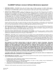
HMI License Agreement
HYTROL’S HMI SOFTWARE LICENSE AGREEMENT
U.S.-Canada-Mexico
IMPORTANT, PLEASE READ THIS FIRST. THIS IS A LICENSE AGREEMENT.
Hytrol is willing to license the accompanying HMI software to you only upon the condition that you accept
all of the terms contained in this license agreement and any supplementary or unique license terms included
herewith ("Agreement").
READ THE TERMS AND CONDITIONS OF THIS AGREEMENT CAREFULLY BEFORE
SELECTING THE "I ACCEPT" BUTTON ON THE HMI SCREEN. BY SELECTING THE "I
ACCEPT" BUTTON, YOU ARE CONSENTING TO BE BOUND BY ALL THE TERMS OF THE
LICENSE AGREEMENT, AND THE SOFTWARE WILL BE ACTIVATED.
IF YOU ARE NOT WILLING TO BE BOUND BY THIS AGREEMENT AND YOU DO NOT AGREE
TO All OF ITS TERMS AND CONDITIONS, SELECT "I REJECT" ON THE HMI SCREEN -- WHICH
WILL CANCEL THE ACTIVATION OF THE SOFTWARE.
YOUR USE OF THE SOFTWARE ALSO INDICATES YOUR ASSENT TO BE BOUND BY THE
LICENSE TERMS SET FORTH HEREIN. IF YOU DO NOT AGREE WITH THE TERMS AND
CONDITIONS OF THIS AGREEMENT, PROMPTLY CONTACT HYTROL CONVEYOR COMPANY
AT (870) 935-3700 OR BY MAIL AT: 2020 HYTROL DRIVE, JONESBORO, ARKANSAS 72401.
COPYING OF THIS SOFTWARE PROGRAM OR ITS DOCUMENTATION EXCEPT AS
PERMITTED BY THIS LICENSE IS STRICTLY PROHIBITED, CONSTITUTES COPYRIGHT
INFRINGEMENT UNDER THE LAWS OF YOUR COUNTRY, AND MAY SUBJECT YOU TO
LIABILITY FOR DAMAGES OR CRIMINAL PENALTIES.
1. Grant of License
Hytrol Conveyor Company, Inc. ("Hytrol") grants you a nonexclusive, nontransferable license to use the
enclosed program (the "Software") and its printed manual and other accompanying material
("Documentation") with the associated equipment owned by you or under your control, according to the
terms and conditions of this License Agreement. This License Agreement permits a single user to activate
and use one instance of this software on only one conveyor unit at one location at any one time.
Back-Up Copy: Regardless of which version of the Software you have acquired, you may make only one
archival (back-up) copy of the Software. Such archival copy may not be installed on another HMI, unless
express written consent is obtained from Hytrol. The archival copy may not be used or installed as long as
another copy of the Software is installed on any conveyor. If the Documentation is in printed form, it may
not be copied. If the Documentation is in electronic form, you may print out one (1) copy, which may not
be copied.
Upgrades: If this Software is labeled as an upgrade to software previously licensed to you, you must
destroy all copies of the replaced software, including any copies resident on your hard disk drive. Hytrol
reserves the right to require you to show satisfactory proof that previous copies of the Software have been
destroyed. Software patches, if any, provided to you by Hytrol or an authorized third party in connection
with the Software licensed to you hereunder, shall be subject to the terms and conditions of this License
Agreement unless otherwise specified at the time of delivery.
III
HMI License Agreement
2. RESTRICTIONS:
UNITED STATES COPYRIGHT LAWS, INTERNATIONAL TREATIES, AND ALL OTHER
APPLICABLE NATIONAL OR INTERNATIONAL LAWS PROTECT THIS SOFTWARE. THIS
SOFTWARE MAY NOT BE USED OR TRANSFERRED OUTSIDE OF THE WESTERN
HEMISPHERE (U.S., Canada, Mexico, Caribbean Islands and Latin America), EXCEPT AS
EXPRESSLY DEFINED IN THIS AGREEMENT AND AGREED TO BY THE USER.
You May Not:
1.
2.
3.
4.
5.
6.
copy the Software or Documentation except as permitted by this license.
distribute, rent, loan, lease, sell, sublicense or otherwise transfer all or part of the
Software, Documentation or any rights granted hereunder to any other person
without the prior written consent of Hytrol.
remove, alter or obscure any proprietary notices, labels or marks from the
Software or Documentation.
modify, translate, adapt, arrange or create derivative works based on the
Software or Documentation for any purpose.
transmit the Software or Documentation over a network, by telephone or
electronically using any means.
reverse engineer, decompile or disassemble the Software or Documentation
3. Copyright
Title and copyrights to the Software, Documentation and accompanying materials and any copies
made by you remain with Hytrol. Unauthorized copying of the Software or Documentation, or
failure to comply with the above restrictions, will result in automatic termination of this license,
and may subject you to liability for damages or criminal penalties.
4. Limited Warranties
Hytrol warrants that for a 90 day period beginning on the date of delivery of the Software to you, the
Software will provide the facilities and functions generally described in the Documentation and that the
media on which the Software is furnished and the Documentation accompanying the Software will be free
from defects in materials and workmanship under normal use.
EXCEPT FOR THE ABOVE EXPRESS LIMITED WARRANTIES, HYTROL MAKES NO
WARRANTIES, EXPRESS, IMPLIED OR STATUTORY. HYTROL SPECIFICALLY DISCLAIMS
ANY OTHER WARRANTY INCLUDING THE IMPLIED WARRANTY OF MERCHANTABILITY OR
FITNESS FOR A PARTICULAR PURPOSE. HYTROL DOES NOT WARRANT THAT THE
OPERATION OF THE SOFTWARE WILL BE UNINTERRUPTED OR ERROR-FREE.
The above exclusions may not apply to you as some jurisdictions do not allow the exclusion of implied
warranties. In addition to the above warranty rights, you may also have other rights, which vary from
jurisdiction to jurisdiction.
Hytrol's entire liability and your exclusive remedy under this warranty will be, at Hytrol's option, to attempt
to correct or work around errors or to replace the defective media or documentation. This remedy is subject
to you contacting Hytrol within ninety (90) days from the date of delivery of the Software to you.
Following expiration of this ninety (90)-day period, Hytrol will replace any defective or damaged device in
return for payment of the cost of a replacement device plus a fee for handling and shipment.
5. LIMITATION OF LIABILITY
IN NO EVENT WILL HYTROL BE LIABLE FOR ANY LOSS OR DAMAGES OF ANY KIND,
INCLUDING LOSS OF DATA, LOST PROFITS, COST OF COVER OR OTHER SPECIAL,
INCIDENTAL, CONSEQUENTIAL OR INDIRECT DAMAGES ARISING OUT OF THE USE OR
INABILITY TO USE THE SOFTWARE OR DOCUMENTATION, HOWEVER CAUSED AND ON
IV
HMI License Agreement
ANY THEORY OF LIABILITY. THIS LIMITATION WILL APPLY EVEN IF HYTROL OR ANY
HYTROL RESELLER HAS BEEN ADVISED OF THE POSSIBILITY OF SUCH LOSS OR DAMAGE.
YOU ACKNOWLEDGE THAT THE LICENSE FEE REFLECTS THIS ALLOCATION OF RISK.
Hytrol shall have no responsibility or liability whatsoever arising from loss or theft of the Software.
Specifically, Hytrol shall not be obligated to replace any lost or stolen software. You are solely responsible
for safeguarding the Software from loss or theft and protecting your investment through insurance or
otherwise. The above limitation may not apply to you because some jurisdictions do not allow the
limitation or exclusion of liability for incidental or consequential damages.
6. Out of Country Sales
A. Canadian Sales
If you purchased this product in Canada, you agree to the following: The parties hereto confirm
that it is their wish that this Agreement, as well as other documents relating hereto, including
Notices, have been and shall be written in the English language only. Les parties aux présentes
confirment leur volonté que cette Convention de même que tous les documents y compris tout avis
qui s'y rattache, soient rédigés en langue anglaise.
B. Mexican Sales
If you purchased this product in Mexico, you agree to the following: The parties hereto confirm
that it is their wish that this Agreement, as well as other documents relating hereto, including
Notices, have been and shall be written in the English language only. Las partes aqui involucradas
confirman el deseo de que este Acuerdo, al igual que otros documentos relacionados al mismo
incluyendo todo tipo de Notas, sea y deba ser escrito únicamente en Inglés.
C. Other sales outside of the country
If you purchased this product for use outside of North America, you agree to the following: The
parties hereto confirm that it is their wish that this Agreement, as well as other documents relating
hereto, including Notices, have been and shall be written in the English language only.
7. General.
A.
You are responsible for configuration, management and operation of the Software.
B.
This license shall terminate without further notice or action by Hytrol if you, the licensee, shall
become
bankrupt, make an arrangement with your creditors or go into liquidation.
C. This Agreement shall not be governed by the UN Convention on Contracts for the Sale of Goods..
This Agreement is the entire agreement between us and supersedes any other communications or
advertising with respect to the Software and Documentation. If you have any questions, please contact
your Authorized Hytrol Distributor.
D. If any provision of these license conditions is found to be invalid or otherwise unenforceable, the
further conditions of this license will remain fully effective and the parties will be bound by
obligations which approximate, as closely as possible, the effect of the provision found invalid or
unenforceable, without being themselves invalid or unenforceable.
E. If any provision of this Agreement shall be held to be invalid or unenforceable for any reason by a
court of competent jurisdiction, the remaining provisions shall continue to be valid and enforceable. If
said court finds that any provision of this Agreement is invalid or unenforceable, but that by limiting
such provision it would become valid and enforceable, then such provision shall be deemed to be
written, construed, and enforced as so limited.
V
HMI License Agreement
F. The laws of the State of Arkansas shall govern this agreement. Each party agrees that any dispute
arising hereunder shall be heard and litigated exclusively in the Federal and State courts located in
Jonesboro, Craighead County, Arkansas. Each party hereby consents to the jurisdiction of said courts.
G. If you have any questions please send written inquires to: Hytrol Conveyor Company, Inc.,
Technology Center, 2020 Hytrol Drive, Jonesboro, Arkansas 72401.
VI
PLC License Agreement
HYTROL’S PLC SOFTWARE LICENSE AGREEMENT
U.S.-Canada-Mexico
IMPORTANT, PLEASE READ THIS FIRST. THIS IS A LICENSE AGREEMENT.
Hytrol is willing to license the accompanying PLC software to you only upon the condition that you accept
all of the terms contained in this license agreement and any supplementary or unique license terms included
herewith ("Agreement").
READ THE TERMS AND CONDITIONS OF THIS AGREEMENT CAREFULLY BEFORE
SELECTING THE "I ACCEPT" BUTTON ON THE HMI SCREEN. BY SELECTING THE "I
ACCEPT" BUTTON, YOU ARE CONSENTING TO BE BOUND BY ALL THE TERMS OF THE
LICENSE AGREEMENT, AND THE SOFTWARE WILL BE ACTIVATED.
IF YOU ARE NOT WILLING TO BE BOUND BY THIS AGREEMENT AND YOU DO NOT AGREE
TO All OF ITS TERMS AND CONDITIONS, SELECT "I REJECT" ON THE HMI SCREEN -- WHICH
WILL CANCEL THE ACTIVATION OF THE SOFTWARE.
YOUR USE OF THE SOFTWARE ALSO INDICATES YOUR ASSENT TO BE BOUND BY THE
LICENSE TERMS SET FORTH HEREIN. IF YOU DO NOT AGREE WITH THE TERMS AND
CONDITIONS OF THIS AGREEMENT, PROMPTLY CONTACT HYTROL CONVEYOR COMPANY
AT (870) 935-3700 OR BY MAIL AT: 2020 HYTROL DRIVE, JONESBORO, ARKANSAS 72401.
COPYING OF THIS SOFTWARE PROGRAM OR ITS DOCUMENTATION EXCEPT AS
PERMITTED BY THIS LICENSE IS STRICTLY PROHIBITED, CONSTITUTES COPYRIGHT
INFRINGEMENT UNDER THE LAWS OF YOUR COUNTRY, AND MAY SUBJECT YOU TO
LIABILITY FOR DAMAGES OR CRIMINAL PENALTIES.
1. Grant of License
Hytrol Conveyor Company, Inc. ("Hytrol") grants you a nonexclusive, nontransferable license to use the
enclosed program (the "Software") and its printed manual and other accompanying material
("Documentation") with the associated equipment owned by you or under your control, according to the
terms and conditions of this License Agreement. This License Agreement permits a single user to activate
and use one instance of this software on only one conveyor unit at one location at any one time.
Back-Up Copy: Regardless of which version of the Software you have acquired, you may make only one
archival (back-up) copy of the Software. Such archival copy may not be installed on another PLC, unless
express written consent is obtained from Hytrol. The archival copy may not be used or installed as long as
another copy of the Software is installed on any conveyor. If the Documentation is in printed form, it may
not be copied. If the Documentation is in electronic form, you may print out one (1) copy, which may not
be copied.
Upgrades: If this Software is labeled as an upgrade to software previously licensed to you, you must
destroy all copies of the replaced software, including any copies resident on your hard disk drive. Hytrol
reserves the right to require you to show satisfactory proof that previous copies of the Software have been
destroyed. Software patches, if any, provided to you by Hytrol or an authorized third party in connection
with the Software licensed to you hereunder, shall be subject to the terms and conditions of this License
Agreement unless otherwise specified at the time of delivery.
VII
PLC License Agreement
2. RESTRICTIONS:
UNITED STATES COPYRIGHT LAWS, INTERNATIONAL TREATIES, AND ALL OTHER
APPLICABLE NATIONAL OR INTERNATIONAL LAWS PROTECT THIS SOFTWARE. THIS
SOFTWARE MAY NOT BE USED OR TRANSFERRED OUTSIDE OF THE WESTERN
HEMISPHERE (U.S., Canada, Mexico, Caribbean Islands and Latin America), EXCEPT AS
EXPRESSLY DEFINED IN THIS AGREEMENT AND AGREED TO BY THE USER.
You May Not:
1.
2.
3.
7.
8.
9.
copy the Software or Documentation except as permitted by this license.
distribute, rent, loan, lease, sell, sublicense or otherwise transfer all or part of the
Software, Documentation or any rights granted hereunder to any other person
without the prior written consent of Hytrol.
remove, alter or obscure any proprietary notices, labels or marks from the
Software or Documentation.
modify, translate, adapt, arrange or create derivative works based on the
Software or Documentation for any purpose.
transmit the Software or Documentation over a network, by telephone or
electronically using any means.
reverse engineer, decompile or disassemble the Software or Documentation
3. Copyright
Title and copyrights to the Software, Documentation and accompanying materials and any copies
made by you remain with Hytrol. Unauthorized copying of the Software or Documentation, or
failure to comply with the above restrictions, will result in automatic termination of this license,
and may subject you to liability for damages or criminal penalties.
4. Limited Warranties
Hytrol warrants that for a 90 day period beginning on the date of delivery of the Software to you, the
Software will provide the facilities and functions generally described in the Documentation and that the
media on which the Software is furnished and the Documentation accompanying the Software will be free
from defects in materials and workmanship under normal use.
EXCEPT FOR THE ABOVE EXPRESS LIMITED WARRANTIES, HYTROL MAKES NO
WARRANTIES, EXPRESS, IMPLIED OR STATUTORY. HYTROL SPECIFICALLY DISCLAIMS
ANY OTHER WARRANTY INCLUDING THE IMPLIED WARRANTY OF MERCHANTABILITY OR
FITNESS FOR A PARTICULAR PURPOSE. HYTROL DOES NOT WARRANT THAT THE
OPERATION OF THE SOFTWARE WILL BE UNINTERRUPTED OR ERROR-FREE.
The above exclusions may not apply to you as some jurisdictions do not allow the exclusion of implied
warranties. In addition to the above warranty rights, you may also have other rights, which vary from
jurisdiction to jurisdiction.
Hytrol's entire liability and your exclusive remedy under this warranty will be, at Hytrol's option, to attempt
to correct or work around errors or to replace the defective media or documentation. This remedy is subject
to you contacting Hytrol within ninety (90) days from the date of delivery of the Software to you.
Following expiration of this ninety (90)-day period, Hytrol will replace any defective or damaged device in
return for payment of the cost of a replacement device plus a fee for handling and shipment.
5. LIMITATION OF LIABILITY
IN NO EVENT WILL HYTROL BE LIABLE FOR ANY LOSS OR DAMAGES OF ANY KIND,
INCLUDING LOSS OF DATA, LOST PROFITS, COST OF COVER OR OTHER SPECIAL,
INCIDENTAL, CONSEQUENTIAL OR INDIRECT DAMAGES ARISING OUT OF THE USE OR
INABILITY TO USE THE SOFTWARE OR DOCUMENTATION, HOWEVER CAUSED AND ON
VIII
PLC License Agreement
ANY THEORY OF LIABILITY. THIS LIMITATION WILL APPLY EVEN IF HYTROL OR ANY
HYTROL RESELLER HAS BEEN ADVISED OF THE POSSIBILITY OF SUCH LOSS OR DAMAGE.
YOU ACKNOWLEDGE THAT THE LICENSE FEE REFLECTS THIS ALLOCATION OF RISK.
Hytrol shall have no responsibility or liability whatsoever arising from loss or theft of the Software.
Specifically, Hytrol shall not be obligated to replace any lost or stolen software. You are solely responsible
for safeguarding the Software from loss or theft and protecting your investment through insurance or
otherwise. The above limitation may not apply to you because some jurisdictions do not allow the
limitation or exclusion of liability for incidental or consequential damages.
6. Out of Country Sales
A. Canadian Sales
If you purchased this product in Canada, you agree to the following: The parties hereto confirm
that it is their wish that this Agreement, as well as other documents relating hereto, including
Notices, have been and shall be written in the English language only. Les parties aux présentes
confirment leur volonté que cette Convention de même que tous les documents y compris tout avis
qui s'y rattache, soient rédigés en langue anglaise.
B. Mexican Sales
If you purchased this product in Mexico, you agree to the following: The parties hereto confirm
that it is their wish that this Agreement, as well as other documents relating hereto, including
Notices, have been and shall be written in the English language only. Las partes aqui involucradas
confirman el deseo de que este Acuerdo, al igual que otros documentos relacionados al mismo
incluyendo todo tipo de Notas, sea y deba ser escrito únicamente en Inglés.
C. Other sales outside of the country
If you purchased this product for use outside of North America, you agree to the following: The
parties hereto confirm that it is their wish that this Agreement, as well as other documents relating
hereto, including Notices, have been and shall be written in the English language only.
7. General.
A.
You are responsible for configuration, management and operation of the Software.
B.
This license shall terminate without further notice or action by Hytrol if you, the licensee, shall
become
bankrupt, make an arrangement with your creditors or go into liquidation.
C. This Agreement shall not be governed by the UN Convention on Contracts for the Sale of Goods..
This Agreement is the entire agreement between us and supersedes any other communications or
advertising with respect to the Software and Documentation. If you have any questions, please contact
your Authorized Hytrol Distributor.
D. If any provision of these license conditions is found to be invalid or otherwise unenforceable, the
further conditions of this license will remain fully effective and the parties will be bound by
obligations which approximate, as closely as possible, the effect of the provision found invalid or
unenforceable, without being themselves invalid or unenforceable.
F.
If any provision of this Agreement shall be held to be invalid or unenforceable for any reason by a
court of competent jurisdiction, the remaining provisions shall continue to be valid and enforceable. If
said court finds that any provision of this Agreement is invalid or unenforceable, but that by limiting
such provision it would become valid and enforceable, then such provision shall be deemed to be
written, construed, and enforced as so limited.
IX
PLC License Agreement
F. The laws of the State of Arkansas shall govern this agreement. Each party agrees that any dispute
arising hereunder shall be heard and litigated exclusively in the Federal and State courts located in
Jonesboro, Craighead County, Arkansas. Each party hereby consents to the jurisdiction of said courts.
G. If you have any questions please send written inquires to: Hytrol Conveyor Company, Inc.,
Technology Center, 2020 Hytrol Drive, Jonesboro, Arkansas 72401.
X
Chapter 1: Overview of ZipLogix
Installation
1
Inspection and inventory of components should be
conducted upon receiving packages. Check the number of
items received against the parts checklist below. Examine
condition of equipment to determine if any damage has
occurred during shipment.
Electrical Code: All motor controls and wiring shall conform to
the National Electrical Code (Article 670 or other applicable articles)
as published by the National Fire Protection Association and as
approved by the American Standards Institute, Inc.
1.1 Parts Checklist
1 each- Main Control Panel
1 each - Warning Device
2 per each Induction Lane - Photo Eye Kit
2 each – Combiner Jam PE Kit
1.2 Mounting The Hardware
1.2.1 CONTROL DEVICE MOUNTING CONSIDERATIONS
A) Control stations should be so arranged and located that the
operation of the equipment is visible from them, and shall be
clearly marked or labeled to indicate the function controlled.
B) A conveyor shall not be started until employees in the area are
alerted by a signal or by a designated person that the
conveyor is about to start. When a conveyor would cause
injury when started and is automatically controlled or must be
controlled from a remote location, an audible device shall be
provided which can be clearly heard at all points along the
conveyor where personnel may be present. The warning
device shall be actuated by the controller device starting the
conveyor and shall continue for a required period of time
before the conveyor starts. A flashing light or similar visual
warning may be used in conjunction with or in place of the
audible device if more effective in particular circumstances.
Where system function would be seriously hindered or
adversely affected by the required time delay or where the
1-1
Chapter 1 : Overview of ZipLogix
C) intent of the warning may be misinterpreted (i.e., a work area
with many different conveyors and allied devices), clear,
concise, and legible warning shall be provided. The warning
shall indicate that conveyors and allied equipment may be
started at any time, that danger exists, and that personnel
must keep clear. The warnings shall be provided along the
conveyor at areas not guarded by position or location. If the
supplied warning device is not loud enough to easily be heard
the full length of the conveyor because of length and/or noise,
then either a louder device or an additional device should be
installed to properly warn personnel.
D) Remotely and automatically controlled conveyors, and
conveyors where operator stations are not manned or are
beyond voice and visual contact from drive areas, loading
areas, transfer points, and other potentially hazardous
locations on the conveyor path not guarded by location,
position, or guards, shall be furnished with emergency stop
buttons, pull cords, limit switches, or similar emergency stop
devices. Connection points are provided in the control panel
to put these ‘customer supplied’ devices in series with the EStop safety circuit. See the schematics provided for the proper
connection points.
All such emergency stop devices shall be easily identifiable
in the immediate vicinity of such locations unless guarded by
location, position, or guards. Where the design, function, and
operation of such conveyor clearly are not hazardous to
personnel, an emergency stop device is not required.
The emergency stop device shall act directly on the control of
the conveyor concerned and shall not depend on the stopping
of any other equipment. The emergency stop devices shall be
installed so that they cannot be overridden from other
locations.
E) Inactive and unused actuators, controllers, and wiring should
be removed from control stations and panel boards, together
with obsolete diagrams, indicators, control labels, and other
material that serve to confuse the operator.
1-2
Chapter 1 : Overview of ZipLogix
1.2.2 MOUNTING THE PANELS
A) The control panels have a NEMA 1 rating, which is a rating intended
for indoor use primarily to provide a degree of protection against the
contact with the enclosed equipment or locations where unusual
service conditions do not exist.
Figure 1-1
B) The main control panel should normally be mounted near the
combiner area. The main control panel should always be within a
distance of the “Homerun Cable” from the “I/O Block”, and electrical
devices on the conveyor should be within a distance of the supplied
cables, from the “I/O Block”. (Figure 1-1 )
1.2.3 SAFETY DEVICES
A) All safety devices, including wiring of electrical safety devices, shall
be arranged to operate in a “Fail-Safe” manner, that is, if power
failure or failure of the device itself would occur, a hazardous
condition must not result.
B) Emergency Stops and Restarts. Conveyor controls shall be so
arranged that, in case of emergency stop, manual reset or starts at
the location where the emergency stop was initiated, shall be
required of the conveyor(s) and associated equipment to resume
operation.
C) Before restarting a conveyor, which has been stopped because of an
emergency, an inspection of the conveyor shall be made and the
cause of the stoppage determined. The starting device shall be
locked out before any attempt is made to remove the cause of
1-3
Chapter 1 : Overview of ZipLogix
stoppage, unless operation is necessary to determine the cause or to
safely remove the stoppage.
Refer to ANSI Z244.1-1982, American National Standard for
Personnel Protection – Lockout/Tagout of Energy Sources –
Minimum Safety Requirements and OSHA Standard Number
29 CFR 1910.147 “The Control of Hazardous Energy
(Lockout/Tagout).”
1.3 Wiring Specifications
Power required to ZipLogix’s control panel is 460 VAC three phase with
a range of 400 – 500 VAC. Incoming power wires should be rated for the
needed current requirement. Improper voltage / wiring may damage
controls.
1.3.1 CONNECTION RECOMMENDATIONS
A) Connecting the E-Stop Circuit:
• If this combiner is part of a system:
ZipLogix’s emergency stop circuit must be put in series with
the system’s E-Stop circuit. You may do this by wiring
terminals 3 and 4 in series with the other system E-Stop
devices. Then connect terminals 2 and 5 to normally open
contacts on the system’s E-Stop relay. Refer to ZipLogix’s
hardwire schematic on drawing ED-10037-04 to view these
connection points. This will allow any E-Stop device in the
system to stop the combiner.
•
If this combiner is not part of a system:
If this combiner is stand-alone and will not be started and
stopped by a central control system, connect the E-Stop
circuit per the following instructions. Refer to ZipLogix’s
hardwire schematic. Jumper terminal 2 to terminal 3. This
will supply the power for the E-Stop circuit. If any other
safety devices are installed that must stop the combiner, wire
them in series between terminals 4 and 5. If no other safety
devices are to be connected, jumper terminal 4 to terminal 5.
1-4
Chapter 1 : Overview of ZipLogix
1.3.2 COMMUNICATING WITH OTHERS
A) Conveyor Start Signal The combiner will normally be started
by the central controls of the system, so that it can easily
coordinate the sequence in which all the conveyors in the
system start up. This “Run” signal is sent to ZipLogix via I/6 on
the ZEN Programmable relay. Refer to Chapter 5:
Communicating with ZipLogix for the details on how to use this
signal.
B) Combiner is Ready Signal The “Combiner is Ready” signal is
sent after the combiner is running, up to speed, and ready to be
fed product. This signal is a contact closure where the system’s
voltage is supplied to terminal 12 and it is sent back on terminal
13 when the contact is closed. Refer to Chapter 5:
Communicating with ZipLogix for the details on how to use this
signal.
1.4 Device Specifications
1.4.1 DEVICE REQUIREMENTS
A) The combiner “Jam” photo eyes will be of the type and
connected for ‘dark operation’ (signal “Off” until eye is blocked).
The output signal will be a sourcing (PNP) output. The amp
draw for each photo eye will not exceed 100 mA.
B) The lanes “Detect” and “Exit” photo eyes will be of the type
and connected for ‘dark operation’ (input “Off” until eye is
blocked). The output signal will be a sourcing (PNP) output.
The amp draw for each photo eye will not exceed 100 mA.
C) The warning device connected to the warning output will not
exceed ½ amp.
1-5
Chapter 1 : Overview of ZipLogix
1.4.2 DEVICE MOUNTING LOCATIONS
A) The combiner “Jam” photo eyes do not have a specific
mounting location. Type of product should be taken into
consideration when deciding the location of the “Jam” photo
eyes. The eyes must be able to see all the way across the
combiner belt, and underneath the plows. A reflector should be
mounted on the opposite side of the combiner for each photo
eye. The recommended location for the “Jam” photo eyes, is
illustrated if Figure 1-2, Items 6 & 7.
Figure 1-2
1-6
Chapter 1 : Overview of ZipLogix
B)
An “Exit PE” for each induction lane should be mounted at the
extreme discharge end of each induction lane, looking 90
degrees across the lane at a reflector. (See Figure 1-3, item 5)
C)
A “Detect PE” for each induction lane should be mounted,
11 inches upstream from the “Exit PE”, and looking 90 degrees
across the lane at a reflector. (See Figure 1-3, item 4)
Figure 1-3
1-7
Chapter 1 : Overview of ZipLogix
Figure 1-4
D)
ZipLogix comes equipped with Hytrol’s “Plug-N-Go©” cabling
system. There will be one I/O block, (Figure1-4) to be mounted
near the discharge end of the outside induction lane, on the
same side of the combiner as the control panel. Each device on
the combiner will connect to this I/O block. Also included, will be
all cables necessary to connect all devices to the I/O block.
There will be one main “Homerun” cable provide, to connect the
I/O block to the control panel. This I/O block also has LED’s,
that will aid in troubleshooting.
1-8
Chapter 1 : Overview of ZipLogix
1.5 Encoder Connection
A)
Each gearmotor on the combiner system has an encoder
located on the end of the motor. (Figure 1-4). An encoder cable
will be provided to connect each encoder to it’s corresponding
VFD. The cable end with the connector should be connected to
the X15 port on teach corresponding VFD. The cable end with
the loose wires should be connected at the encoder. Make sure
that each encoder cable is installed in the manner shown in
(Figure 1-5) to insure proper grounding of the cable. The
encoder cables should be ran from each VFD to each encoder
in a manner that isolates it from any high voltage or motor
cables.
Figure 1-4
1-9
Chapter 1 : Overview of ZipLogix
Figure 1-5
B) The connection points for the encoder cable at the encoder end
are listed in (Figure 1-6)
Figure 1-6
1-10
Chapter 2 : Checking Installation
Checking Installation
After all mounting and wiring of devices has been completed, go
through the following procedure to ensure that all wiring is properly
connected.
2.1 Checks Before Applying Power
A)
MAKE SURE POWER FEEDING ZIPLOGIX IS OFF! Check to
make sure the AC supply power wires are properly connected.
The “Ground” should be connected to the ground distribution lug
labeled “PE”.
B)
Set meter for ohms and check from “PE” to each phase of the
460v power wires, to ensure that they are not grounded. Also
check from “Ground” to terminal +24 to it is not grounded.
C)
Make sure all wires are properly connected and covers are in
place. Make sure all personnel are clear of all moving parts,
wiring, and electrical devices.
D)
ATTENTION: The user is responsible for conforming to all
applicable local, national, and international codes with the field
wiring. The user is also responsible for supplying the correct line
voltage. Failure to observe this precaution could result in
damage to, or destruction of, the equipment.
2.2 Checks After Applying Power
A) Make sure that everyone in the area knows that you are going
to apply power to the controls! Turn “On” the 460 VAC supply
voltage to the control panel. Set meter for “VAC” and check
from phase to phase, to ensure that supply power is 460 VAC.
B) Go to “I/O Menu” screen. On each screen, check the operation
of each device to ensure that it is wired correctly and working
properly. Check the operation of the emergency stop circuit by
pushing and pulling the emergency stop pushbutton located
beside the HMI. The E-Stop Button indicator light should
illuminate when the E-Stop button is pushed, and the relay SR1
should de-energize. If the E-Stop circuit doesn’t change states,
2-1
Chapter 2 : Checking Installation
C) another E-Stop in the circuit may be tripped, the central control
system is not powered up, or there is a wiring problem.
D) Check each Induction VFD to insure that it is not faulted. The
HMI should display a message notifying the user of a fault. Each
VFD also has an LED Indicator that reflects the state of the
Drive. With the power on and the ZipLogix not running, this LED
will be Amber. If the drive is faulted, this LED will be Red.
(FIGURE 2-1)
Figure 2-1
2-2
Chapter 3 : Overview of ZipLogix Touchscreens
Overview of ZipLogix Touch Screens
3
Before getting into the configuration of ZipLogix, you will
be introduced to the operation of the touch screens. This
chapter will explain the purpose, features, and operation of
each screen.
3.1
Configuration Protection
A password will be required to change the setup parameters in
ZipLogix. This is intended to keep unauthorized personnel from changing
setpoints, and to prevent accidental changes.
The Screens may be viewed without the password enabled, but
changes will not be allowed without entering the correct password. There
is a message at the bottom of each screen with setpoints, to display the
state of the password. It will read either “Password Enabled” or
“Password Disabled”
3.2
Explanation of Screens
You must touch the desired button or number field on the screen to
select it or to change the value. Minimal pressure needs to be applied
when touching objects on the touch screens.
Touching a number field brings up a numeric keypad to allow you to
change the value of the associated parameter, provided the password is
enabled. Once you have pressed the correct number(s), press the
“ENTER” key to accept this value. When you press “ENTER”, the box
will have the new value.
To remove any numeric keypad from view, press the “
“ push
button at the bottom of the keypad. (Figure 3-1)
3-1
Chapter 3 : Overview of ZipLogix Touchscreens
• NUMERIC ENTRY KEYPAD
Figure 3-1
3-2
Chapter 3 : Overview of ZipLogix Touchscreens
• MAIN MENU
The Main Menu contains the selection buttons for the Setup, Speeds, I/O Menu,
Calibration, and Fault Screens.
3-3
Chapter 3 : Overview of ZipLogix Touchscreens
• SETUP SCREEN
The “Setup Screen’ , is where you will enter the parameters that will
determine how the ZipLogix will operate. Before you can change any of these
settings, you will have to enable the password. The “Gap Required”, is the
amount of gap that require between boxes. The “Seconds To Allow For A Jam”,
is a setting to delay the Jam fault when one of the “Jam Eyes” are blocked. The
“Number of Priority Boxes”, is the setting for the number of boxes to release on a
lane, when Priority is on for that lane. The “Next Priority Box Timer”, is how long
you want to wait for a box to show up on a lane that has Priority on, before
moving to the next lane. The “Induct Lanes Accel and Decel Time” is the setting
for the ramp up and down on each of the induct lanes. The “Longest Box”, is the
setting for the longest box that will be run on the system. This setting is used in
conjunction with the Jam function. To change any of the settings, touch the
corresponding numerical field, and the keypad screen will open. Enter a value
and press the “Return Key”.
3-4
Chapter 3 : Overview of ZipLogix Touchscreens
• SPEED SETUP SCREEN
On the “Speed Setup” screen you can enter the speeds that you want the
units to run. The induction lanes need to run the same speed as the combiner.
The plow speeds run at a vector speed of the combiner. The formula for setting
the plow speeds is as follows…..
combinerspeed
cos ofplowangle
Combiner Speed divided by the cosine of the angle of the plows in relation to the
combiner. The plow may need to be adjusted beyond this calculation, depending on the
reaction of the specific product on the plows.
3-5
Chapter 3 : Overview of ZipLogix Touchscreens
• I/O MENU SCREEN
On the “Monitor I/O Menu” screen you can choose which I/O screen you
wish to view.
3-7
Chapter 3 : Overview of ZipLogix Touchscreens
• I/O SCREENS
3-7
Chapter 3 : Overview of ZipLogix Touchscreens
• FAULT SCREEN
The “Fault Screen’ will display any active VFD fault on the system. It will display
which VFD is faulted and what the fault is.
3-8
Chapter 3 : Overview of ZipLogix Touchscreens
Communicating With ZipLogix
4
ZipLogix allows for signals to easily interlock the Main system with ZipLogix.
4.1
Interlock Signals with Others
There are several signal interlocks provided to allow the system to
coordinate the combiner with the other associated conveyors. The wiring
connections for these signals are explained in Chapter 1: Installation.
•
Combiner Run Signal: The “Combiner Run Enable Signal” can be
sent to ZipLogix through a dry contact closure. This will be a 120VAC
signal from ZipLogix through a system dry contact and back to
ZipLogix. This allows the system to start and stop the combiner. When
the signal is dropped the combiner will stop.
•
Combiner Ready Signal: The “Combiner Ready Signal” will be sent to
the system after the combiner is running and up to speed, to let the
system that it is “Ok To Feed” the Combiner. This signal will be
dropped when the combiner is stopped for any reason. This signal
requires a system supplied voltage, through a dry contact in the
ZipLogix, and back to the system.
•
Combiner No Faults Signal: The “No Faults Detected” signal will be
sent to the system whenever there is no active faults on the ZipLogix.
When the ZipLogix faults, this signal will be dropped. This signal
requires a system supplied voltage, through a dry contact in the
ZipLogix, and back to the system.
•
Priority Signal: ZipLogix can receive a “Priority” signal for each
Induction lane. This will be a 120VAC signal from ZipLogix through a
system dry contact and back to ZipLogix. This allows the system to turn
the Priority signal on for a given lane. Once the priority is on, ZipLogix
will release the set number of boxes from that lane before releasing
from the other lanes, as long as there is product available.
•
Run Only Signal: ZipLogix can receive a “Run Only” signal for each
Induction lane. This will be a 120VAC signal from ZipLogix through a
system dry contact and back to ZipLogix. This allows the system to turn
the Run Only signal on for a given lane. Once the Run Only is on,
ZipLogix will release product from that lane only, and the other lanes
will be disabled.
3-12
Chapter 5 : Operating ZipLogix
Operating Your Combiner
5
This chapter will explain how to use ZipLogix to operate the
combiner. The touch screens were designed to be easy and self
explanatory.
5.1 Starting the Combiner
CAUTION: Make sure the conveyor is completely assembled and ready to
run. Make sure everyone is clear of all moving parts and that all tools and
foreign objects have been removed from the conveyor. The controls and
the VFDs should be powered up. Failure to observe these precautions
could result in damage to, or destruction of, the equipment.
The combiner will normally be started by the central controls of the
system, so that it can easily coordinate the sequence in which all the
conveyors in the system start up. This “Run” signal is sent to ZipLogix
input “I/6”. The combiner will stop when power on input “I/6” is dropped. If
combiner is stopped by an error, the error must be reset by turning the
combiner “On/Off” switch to “Off”, and then pressing the “Reset” buttton.
The “Conveyor Ready” signal “Wire 13” can be monitored by the system to
detect when the combiner has been stopped by something other than the
system. The conveyors upstream from the combiner should not be started
until the “Conveyor Ready” signal is seen.
5-1
Chapter 5 : Operating ZipLogix
When the combiner is started for the first time after it has been
powered down, any boxes on the combiner will be run through. Each
induction lane will start one at a time, to allow any box that was caught in
transition from the induction unit to the Zipper belt, during shutdown, to
be purged through. This is done to insure that a jam is not created.
If combiner does not start, check these items: the combiner “On/Off”
switch is set to “Off”, an E-Stop has been tripped, the ZipLogix is not
receiving a Run signal from the system, an error condition exists (check
on the “Fault Screen”, correct, and reset errors).
5.2 Stopping the Combiner
The combiner may be stopped by pressing the “E-Stop” button,
switching the “On/Off” to “Off”, or dropping the “Run” signal from the
system.
If the combiner is stopped by an E-Stop condition (E-Stop pushbutton
pressed, safety cable pulled, etc…), then the E-Stop must be reset at the
triggered device.
If any errors occur, then the problem must be corrected and the fault
must be by cleared by turning the combiner “On/Off” switch to “Off”, and
then pressing the “Reset” buttton.
5.3 Changing Speeds
The speeds of the combiner and induction lanes, may be changed
form the HMI. On the “Main Menu” press the button that is labeled
“Speeds”. This will take you to the “Speeds Setup” screen. You must
first enable the Password by pressing the button labeled “Enable
Password”. A keypad will appear, enter the correct password and
press the “Return Key”. As you enter the password, the digits will
appear in the upper left hand corner next to “PASSWORD:”. If you
enter the wrong password the digits will turn to asterisks (*) to let you
know that the wrong password was entered. Once the password is
enabled, a message will notify you that the password is enabled. Once
you leave this screen, the password will no longer be enabled.
With the password enabled, you can touch the numeric field next to
the speed that you want to change. A keypad will appear, enter the
speed, and press the “return” key. The speeds for the Induction Lanes
will all be changed at once. In normal operation, the Induction Lanes
will run at a speed equal to the Zipper belt. Each of the plow speeds
can be changed individually. This is because the plows may not be
exactly at the same angle in relation to the Zipper belt, thus they will
need to be operated at different speeds
5-2
Chapter 6 : Troubleshooting ZipLogix
Troubleshooting with ZipLogix
6
ZipLogix will immediately display an error message on
the Main Menu whenever an error occurs. The Combiner
will immediately shut down when one of these conditions
occur. Ensure that the cause of the error condition has
been remedied and all personnel are clear before
attempting to restart the combiner. After repairing the
condition that caused the error, the error will need to be
cleared by turning the combiner “On/Off” switch to “Off”,
and then pressing the “Reset” buttton.
6.1 Error Messages
If the ZipLogix detects a fault, a message will appear on the Main Menu
notifying whether the combiner or which lane has the fault. At this point you
can navigate to the Fault Screen, to see what the fault is. All of the faults
displayed here will be VFD faults.
6.1.1 Jam Detected
This error message will be displayed anytime one of the “Jam PE’s” have
been blocked for a predetermined amount of time. If this error occurs, the
jammed boxes should be cleared on the combiner, and the fault cleared by
turning the combiner “On/Off” switch to “Off”, and then pressing the “Reset”
buttton.
6-1
Chapter 6 : Troubleshooting ZipLogix
6.1.2 VFD Fault Troubleshooting Guide
6-2
Chapter 6 : Troubleshooting ZipLogix
6-3
Chapter 6 : Troubleshooting ZipLogix
6-4
Chapter 6 : Troubleshooting ZipLogix
6.2 Using the Input and Output Screens
The input and output screens can be useful in troubleshooting
problems. The state of the device can be monitored at any time in any
mode. This is very useful at initial startup to check for correct wiring and
proper operation. One person can actuate each device while another
watches the state displayed on the screen.
You can navigate to the I/O screens by pressing the “I/O Menu”
button on the Main Menu, and then pressing the button for the screen that
you wish to view.
6.3 Troubleshooting Tips
If one of the Induction Lanes is running all the time, and product is not
releasing from the other lanes, check the following……..
•
•
Make sure that the lane that is running is not set to “Run Only”
Check the “Exit PE”, to insure that it is aligned with the reflector.
If one of the “Induction Lanes” is stopped, with present, check the
following……..
•
Make sure that the “Detect PE” for that lane is aligned with the
reflector.
6-5
Chapter 7 : Using MoviDrive Keypad
7
Using the MoviDrive® Keypad
The Movidrive keypad can be used for multiple functions. You
can use it for troubleshooting the VFD, saving, and loading the
program and parameters. This section will explain how to use the
keypad to perform these functions.
7.1
Basic functions of the keys
This document is a step-by-step example for saving and loading parameter files and
programs with the DBG Keypad for the MOVIDRIVE® and MOVIDRIVE®
compact.
DBG Keypad for MOVIDRIVE® and MOVIDRIVE® compact
General function of the keys.
Next menu command or increase value in edit mode.
Previous menu command or decrease value in edit mode.
One menu level down or activate edit mode for the menu command.
One menu level up or deactivate edit mode for the menu command.
Cancel and return to main display.
Pressing this key in the event of a fault gives direct access to Parameter
840 [Manual Reset].
7-1
Chapter 7 : Using MoviDrive Keypad
7.2 Changing the language
Should the keypad display come up in a language other in English, do the following
(this example is in German with the default SHORT MENU on).
Press Key
Display
REGLERSPERRE
STROM:
0
Description/Comments
Press the Q key to return to the
main display.
A
840/
NEIN
MANUELLER RESTE
Press the down arrow key.
835/
KEINEREAKT
REAKT. TF-MELDUNG
Press the down arrow key.
820/
EIN
4-Q-BETRIEB1
Press the down arrow key.
803/
AUS
PARAMETWESPERRE
Press the down arrow key.
802/
NEIN
WERSEINSELLUNG
Press the down arrow key.
801/ DEUTSCH
SPRACHE
Press the down arrow key.
801/ DEUTSCH
SPRACHE
Press the right arrow key. This will
put you in “EDIT” mode.
801/ ENGLISH
LANQUAGE
Press the up arrow key; the display
will change to ENGLISH.
CONTR. INHIBT
CURR.:
0
Press the Q key to return to the
main display.
A
7-2
Chapter 7 : Using MoviDrive Keypad
7.3 Accessing full parameter set
To access the full parameter set of the drive the SHORT MENU must be set to OFF
Press Key
Display
CONTR. INHIBT
CURR.:
0
Description/Comments
Press the Q key to return to the
main display.
A
840/
0FF
MANUAL RESET
Press the down arrow key.
835/
NO RESPONSE
RESP. TF-SIGNAL
Press the down arrow key.
820/
ON
4-QUADR-OPER.1
Press the down arrow key.
803/
OFF
PARAMETER LOCK
Press the down arrow key.
802/
NO
FACTORY SETTING
Press the down arrow key.
801/ ENGLISH
LANGUAGE
Press the down arrow key.
800/
ON
Press the down arrow key.
ON
Press the right arrow key. This will
put you in “EDIT” mode.
OFF
Press the up arrow key to turn the
SHORT MENU off.
SHORT MENU
800/
SHORT MENU
800/
SHORT MENU
CONTR. INHIBT
CURR.:
0
Press the Q key to return to the
main display.
A
7-3
Chapter 7 : Using MoviDrive Keypad
7.4 Saving program & parameters from VFD to Keypad
Following is the procedure to save the inverter program from the drive to the DBG
Keypad. This can be done while the drive is running:
Press Key
Display
CONTR. INHIBT
CURR.:
0
Description/Comments
Press the Q key to return to the
main display.
A
9..
IPOS
PARAMETERS
Press the down arrow key.
8..
UNIT
FUNCTIONS
Press the down arrow key.
80.
SETUP
Press the right arrow key.
800
OFF
Press the right arrow key.
SHORT MENU
-- WAIT--
—
807
NO
COPY MDX--> DBG
Press the down arrow key.
807
NO
COPY MDX--> DBG
Press the right arrow key. This will
put you in “EDIT” mode.
807
YES
COPY MDX--> DBG
Press the up arrow key, the display
will change from “NO” to “YES”.
COPYING
DATA
Display while data is copying.
807
NO
COPY MDX--> DBG
When copying is complete display
will return to “NO”.
CONTR. INHIBT
CURR.:
0
Press the Q key to return to the
main display (display example if
the drive is not running).
SPEED:
CURR.:
A
1500 rpm
1.68 A
Press the Q key to return to the
main display (display example if
the drive is running).
The parameter file and any inverter program are now saved on the DBG Keypad.
7-4
Chapter 7 : Using MoviDrive Keypad
7.5 Saving program & parameters from Keypad to VFD
Following is the procedure to copy the program from the DBG Keypad to the
inverter. NOTE: input DI00 (terminal X13:1 on the MOVIDRIVE® or terminal
X10:9 on the MOVIDRIVE® compact must be low (24VDC must be removed while
copying).
Key
Display
CONTR. INHIBT
CURR.:
0
Description
Returns to main display (drive not
running)
A
9..
IPOS
PARAMETERS
Press the down arrow key.
8..
UNIT
FUNCTIONS
Press the down arrow key.
80.
SETUP
Press the right arrow key.
800
OFF
Press the right arrow key.
SHORT MENU
-- WAIT --
—
807
NO
COPY MDX--> DBG
Press the down arrow key.
806
NO
COPY DBG--> MDX
Press the down arrow key.
806
NO
COPY DBG--> MDX
Press the right arrow key. This will
put you in “EDIT” mode.
806
YES
COPY DBG--> MDX
Press the up arrow key, the display
will change from “NO” to “YES”.
COPYING
DATA
Display while data is copying.
806
NO
COPY DBG--> MDX
When copying is complete display
will return to “NO”.
CONTR. INHIBT
CURR.:
0
Press the Q key to return to the
main display.
A
The parameter file and any inverter program saved on the DBG Keypad are now
loaded on the inverter.
7-5
Chapter 7 : Using MoviDrive Keypad
7.6 Manually Running MoviDrive From Keypad
The Movidrive can be ran manually regardless of the wiring or parameter
settings by using the following steps.
* If DI00 (Control Inhibit) is not turned on (24VDC applied), then it must
be jumpered or otherwise energized before continuing.
1. Go to parameter 880 (Manual Run)
a. Press the down arrow twice.
b. Press the right arrow once to 8_ _.
c. Press the down arrow once to 88_.
d. Press the right arrow once to 880 (Manual Operation).
e. Press the right arrow once again to enter the parameter.
2. Press the up arrow to start manual operation.
3. Select the direction of rotation with the left or right arrows
(left=CW,right=CCW)
* Note: Pressing “Q” at any time will stop the motor.
4. Use the up and down arrows to increase and decrease the speed. Press
Q to stop the motor.
To exit Manual Operation:
After pressing Q to stop the motor, press E once then Q once. This
will take you back to the main screen.
7-6
Chapter 7 : Using MoviDrive Keypad
7.7 Manually Resetting Error
If an error occurs on any VFD the status light on the VFD will be red
instead of green or amber. It this occurs, the VFD has faulted. Note the
error displayed and try cycling power to reset the error. If the error is still
present after powering up, the cause of the error must be corrected before it
can be cleared. Look up the error code in the instruction manual to
determine the cause of the error. Correct the cause of the error.
You may directly view the fault code on the VFD using these steps.
Unplug the communication module on the front of the VFD and put in the
DBG keypad provided. Write down the error code displayed on the DBG
keypad for future reference. Press the “E” push button will take you to the
“Manual Reset” parameter (840). Press the up arrow key to reset the error.
7-7
Notes
Notes
Notes
Notes