
1
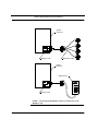
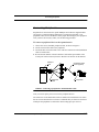
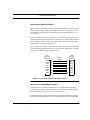
Apollo Multiport Controllers User’s Guide Asynchronous communications for PCI-equipped Solaris™ systems: Apollo Model 4020P Part Number: 15-10101-00, Rev. B Revision Date: December, 2002 Copyright © 2002, Aurora Technologies, Inc., a Carlo Gavazzi Group company. All Rights Reserved. Printed in the United States of America This publication is protected by Federal Copyright Law, with all rights reserved. No part of this publication may be copied, photocopied, reproduced, stored in a retrieval system, translated, transmitted, or transcribed in any form or by any means manual, electric, electronic, electromagnetic, mechanical, optical, or otherwise, in whole or in part without prior written consent from Aurora Technologies, Inc. Limitation of Liability Aurora Technologies, Inc. makes NO WARRANTY, EXPRESSED or IMPLIED, with respect to this manual, and any related items, its quality, performance, merchantability, or fitness for any particular use. It is solely the purchaser’s responsibility to determine its suitability for any particular use. Information contained in this document is subject to change without notice. Trademark Credits Aurora Technologies, the Aurora logotype, Apollo Multiport, Nova Multiport, Aries Multiport, ControlTower, Explorer Multiport, LanMultiServer, Saturn Multiport, SBox, and WanMultiServer are trademarks of Aurora Technologies, Inc., a Carlo Gavazzi Group company. All other registered trademarks and servicemarks are the proprietary property of their respective owners. Declaration of Conformity Konformitätserklärung Déclaration de conformité Declaración de Confomidad Verklaring de overeenstemming Dichiarazione di conformità We/Wir/Nous/Wij/Noi: Aurora Technologies, Inc. 10 Mupac Drive Brockton, MA 02301 USA declare under our sole responsibility that the products, erklären, in alleniniger Verantwortung, daß dieses Produkt, déclarons sous notre seule responsabilité que les produit, declaramos, bajo nuestra sola responsabilidad, que el producto, verklaren onder onze verantwoordelijkheid, dat het product, dichianriamo sotto nostra unica responsabilità, che il prodotto, Apollo Multiport Controller to which this declaration relates is in conformity with the following standard(s) or other documents. auf das sich diese Erklärung bezieht, mit der/den folgenden Norm(en) oder Richtlinie(n) übereinstimmt. auquel se réfère cette déclaration est conforme à la (aux) norme(s) ou au(x) document(s) normatif(s). al que se refiere esta declaracion es conforme a la(s) norma(s) u otro(s) documento(s) normativo(s). waarnaar deze verklaring verwijst, aan de volende norm(en) of richtlijn(en) beantwoordt. a cui si riferisce questa dichiarazione è conforme all/e seguente/i norma/o documento/i normativo/i. EN 55022:1994/A1:1995 Class A ITE emissions requirements (EMC) EN 50082-1:1992 EMC generic immunity standard Warning This is a Class A product. In a domestic environment this product may cause radio interference in which case the user may be required to take adequate measures FCC Notices This device complies with part 15 of the FCC Rules. Operation is subject to the following two conditions: (1) This device may not cause harmful interference, and (2) this device must accept any interference received, including interference that may cause undesired operation. Note: this equipment has been tested and found to comply with the limits for a Class A digital device, pursuant to part 15 of the FCC Rules. These limits are designed to provide reasonable protection against harmful interference when the equipment is operated in a commercial environment. This equipment generates, uses, and can radiate radio frequency energy and, if not installed and used in accordance with the instruction manual, may cause harmful interference to radio communications. Operation of this equipment in a residential area is likely to cause harmful interference in which case the user will be required to correct the interference at his own expense. Contents Chapter 1. About this Manual Manual Organization ...............................................................1-1 Who Should Use This Book ....................................................1-2 Related Manuals ......................................................................1-2 Document Conventions ...........................................................1-3 Getting Help ............................................................................1-3 Registration..............................................................................1-4 Chapter 2. Introducing the Apollo Multiport 4020P Controller Introducing the Apollo Multiport Controllers .........................2-1 Interface options .................................................................2-2 Introducing the Apollo Multiport Controllers .........................2-2 System Requirements ..............................................................2-2 Technical Specification Overview...........................................2-3 Table of Contents iv Contents (continued) Chapter 3. Installing Apollo Multiport Controller Hardware Completing the Product Information Worksheet .................... 3-1 Installation Overview ............................................................. 3-2 Installation Precautions........................................................... 3-2 Unpacking the Hardware ........................................................ 3-4 Other Things You’ll Need....................................................... 3-4 Cabling............................................................................... 3-4 Tools................................................................................... 3-5 Installing the Multiport Card .................................................. 3-5 Connecting Peripherals........................................................... 3-7 Chapter 4. Software Installation and Configuration Installing the Device Driver Software .................................... 4-2 Free Driver and Release Note Downloads......................... 4-2 Asynchronous Device File Names ......................................... 4-2 Setting Up Asynchronous Port Services................................. 4-4 Setting Up Printer Services................................................ 4-5 Setting Up Terminal Services ............................................ 4-5 Bypassing the Carrier Detect (CD) Line............................ 4-7 Setting Up Modem Services .............................................. 4-8 Setting Asynchronous Data Rates...................................... 4-9 Chapter 5. Using Vanguard Multiport Software Viewing Port Parameters with aseinfo.................................... 5-1 Administering Ports with mset ............................................... 5-3 Chapter 6. Troubleshooting Installation Problems .............................................................. 6-1 Clearing Hung Async Ports .................................................... 6-2 The xxtrace Driver Tracing Utility ......................................... 6-3 Using xxtrace Commands .................................................. 6-3 Running xxtrace................................................................. 6-4 Troubleshooting with mset ..................................................... 6-6 mset Error Message ........................................................... 6-7 v Table of Contents Contents (continued) Calling for Support ..................................................................6-7 Support Call Checklist........................................................6-7 Chapter 7. Warranty & Maintenance Information Warranty on Hardware & Software .........................................7-1 Standard Hardware Warranty Policy ..................................7-1 Standard Software Warranty Policy....................................7-1 Appendix A . Cables and Connectors Cabling Overview....................................................................A-1 Serial Connector Pinouts ....................................................A-2 Signal Descriptions.............................................................A-3 Asynchronous Serial Cables....................................................A-4 Asynchronous Modem Cables............................................A-5 Asynchronous Null-Modem Cables ...................................A-5 Synchronous Serial Cables ......................................................A-9 Connecting Synchronous Modems .....................................A-9 Connecting Other Synchronous Devices ............................A-10 Connecting Peripherals.......................................................A-11 RS-232 Functional Pinout ..................................................A-12 RS-422 and RS-485 Support(optional) ..............................A-12 Appendix B . Product Information Worksheet Completing Product Information Worksheet...........................B-1 Index Table of Contents vi Contents (continued) vii Table of Contents CHAPTER 1 About this Manual The Apollo Multiport 4020P Controller User’s Guide describes how to install and use Aurora Technologies Apollo high speed asynchronous multiport controllers for PCI bus systems. Manual Organization The User Manual is organized as follows: Chapter 1, “About this Manual.” Describes purpose, audience, related documents, and document conventions for this guide. Chapter 2, “Introducing the Apollo Multiport 4020P Controller.” Provides a technical overview of Apollo multiport controllers for SPARCs. Chapter 3, “Installing Apollo Multiport Controller Hardware.” Describes unpacking procedures and hardware installation. Chapter 4, “Software Installation and Configuration.” Describes installation of the device driver and the device files that are created under Solaris. Chapter 5, “Using Vanguard Multiport Software.” Describes administration of ports and configuration of electrical interfaces on Apollo multiport controllers. Apollo Multiport Controller User’s Guide 1-1 About this Manual Appendix 6, “Troubleshooting.” Describes potential installation problems, error messages, and diagnostic tools. Chapter 7, “Warranty & Maintenance Information.” Provides warranty and maintenance information for Aurora Technologies’ products. Appendix A, “Cables and Connectors.” Provides wiring diagrams and general cabling information. Appendix B, “Product Information Worksheet.” Provides a record of information on your Aurora Technologies hardware and software. Who Should Use This Book This book is a reference manual for anyone who wants to install, configure, and use Apollo serial controllers in PCI-equipped computer systems. Related Manuals For more information, refer to the following manuals: • Your computer system documentation • Your Solaris documentation • Your peripheral’s documentation. 1-2 Apollo Multiport Controller User’s Guide Document Conventions Document Conventions Table 1 describes the symbolic conventions used in this guide. TABLE 1. Conventions Symbol Description screen display Graphic text that appears on screens, menus and dialog boxes appears in sans serif font. User input User input values appear in boldface. These are characters or commands you type literally. emphasis Italics are used in the text for emphasis, titles, and variables. This caution symbol marks notes about possible damage to computer equipment or data if a procedure or process isn’t followed according to instructions. This warning symbol marks notes about possible electrical shock to yourself or electro-static discharge damage to equipment unless you follow special instructions. This symbol marks special text passages that contain additional information such as notes you should know about or tips you should consider when installing, operating, or maintaining this product. Getting Help If you need to reach us, you can contact us by • The Web: www.auroratech.com for product literature, phone numbers and address. • Phone service: Mon–Fri, 8:30AM–6:00PM Eastern Time For faster service, have your product serial number and your system information available. Apollo Multiport Controller User’s Guide 1-3 About this Manual • FAX: Attn: Customer Service and Support • Email: [email protected] • Mail: Attn: Customer Service and Support Registration To receive warranty coverage on your Aurora product, you must fill out and mail back the Aurora Warranty Registration Card that is located in the back of this manual. Phone support can only be provided after product registration is complete. Hardware and Software Maintenance Agreements can be provided for extended customer support. Sending in this card also lets us keep you up-to-date on the complete line of Aurora Technologies’ products. If you have any questions or comments on your Aurora Technologies’ product, contact our Customer Support Department at [email protected] or your sales representative. 1-4 Apollo Multiport Controller User’s Guide CHAPTER 2 Introducing the Apollo Multiport 4020P Controller Congratulations on purchasing your Aurora Technologies Apollo Multiport™ controller. Combining on-board RISC processing, dedicated data buffers, and flow control processing, Apollo Multiport controllers off-load communications overhead from your host CPU and your network for optimum system performance. Introducing the Apollo Multiport Controllers The Apollo Multiport series of asynchronous PCI-bus controllers provides the performance and reliability needed for high-speed serial communications. Data transfer rates up to 230.4 kbps, full duplex, are supported. Apollo Multiport controllers are available for any SPARC-compatible system or personal computer with a PCI expansion bus, running supported releases of Solaris or Solaris x86. (See the Driver Release Note for supported Solaris releases.) Apollo Multiport Controller User’s Guide 2-1 Introducing the Apollo Multiport 4020P Controller Interface options The Apollo Multiport controllers support the RS-232 interface and are available with either DB-25 or RJ-45 connectors. RS-422 or RS-485 with DB-25 connectors are optionally available. Introducing the Apollo Multiport Controllers The Apollo series of PCI-Bus async controllers offers lower cost, asynchronousonly, multiport capability. It supports asynchronous data transfer rates up to 230.4 kbps, full duplex, simultaneously on all ports. Apollo controllers support the RS-232 interface and are available with either DB25 or RJ-45 connectors. RS-422 or RS-485 with DB-25 connectors are optionally available. System Requirements Aurora’s Apollo Multiport controllers are designed to work with a wide range of systems running Solaris or Solaris x86. Your system must meet the following requirements: 2-2 Workstation: Any SPARC or PC compatible Operating System: Solaris/Solaris x86 (See Driver Release Note for supported releases.) CPU: SPARC or Intel x86 Bus: PCI Memory: 16 Mbytes minimum Disk Drive: 1 Mbyte free in /opt (Solaris) CD-ROM Drive: (optional) Apollo Multiport Controller User’s Guide Technical Specification Overview Technical Specification Overview Table 2 provides a technical specification overview of the Apollo Multiport controllers. TABLE 2. Apollo Multiport Controller Specifications Ports 4 Electrical Interface RS-232 standard RS-422, RS-485 optional Card Connector DB-62 Connector Extensions DB-25 DTE (male or female) RJ-45 optional Speed full duplex, async: 50–230.4 kbps simultaneously on all ports Start/Stop bits 1 and 2 Data bits 5, 6, 7, or 8 bits Interrupt Level Assigned by OS Flow Control Hardware: CTS/RTS Software: XON/XOFF Modem support Full support all lines Modem control CD/DTR/DSR I/O Buffer (per port) 128 Bytes send and receive per port Certification FCC Class A and CE Apollo Multiport Controller User’s Guide 2-3 Introducing the Apollo Multiport 4020P Controller 2-4 Apollo Multiport Controller User’s Guide CHAPTER 3 Installing Apollo Multiport Controller Hardware This chapter describes how to install Apollo Multiport hardware, and contains the following sections: • • • • • Filling out the Product Information Worksheet Taking precautions before you begin Unpacking the Apollo Multiport hardware Installing the Multiport card Connecting peripherals to the card Completing the Product Information Worksheet Before beginning the installation, record the following information in Appendix B, “Product Information Worksheet.” • Apollo Multiport card serial number • The name and model number of the system into which you have installed our product (e.g., Ultra 30). Apollo Multiport Controller User’s Guide 3-1 Installing Apollo Multiport Controller Hardware • The version of the operating system that your system is currently running (for example, Solaris 7). Also complete the product registration card in Chapter 7, “Warranty & Maintenance Information.” to be eligible for technical support. Installation Overview The following table provides an overview of how to install your Apollo Multiport controller and the Aurora device drivers. Steps Description Go to 1 Unpack the multiport controller. “Unpacking the Hardware” on page 3-4 2 Install the card in an empty slot “Installing the Multiport Card” on page 3-5 3 Install the device drivers Chapter 4, “Software Installation and Configuration.” 4 Set up port services for the asynchronous ports Chapter 5, “Using Vanguard Multiport Software.” These steps are described in detail in the following sections and chapters. Installation Precautions Taking the precautions described in this section should help you avoid injury or damage to your equipment. Electrostatic discharge can damage integrated circuits on your multiport cards. 3-2 Apollo Multiport Controller User’s Guide Installation Precautions To prevent such damage from occurring, observe the following precautions during board unpacking and installation. • Handle circuit cards only by their non-conducting edges once you have removed them from their protective antistatic bags. • Stand on a static-dissipative mat. • Wear a grounding strap to ensure that any accumulated electrostatic charge is discharged from your body to the ground. • Install circuit cards as soon as you remove them from their protective anti-static packaging. • Do not leave cards exposed after you unpack them. • If you must put a card down, place it on anti-static packaging or on a rubber mat. Apollo Multiport Controller User’s Guide 3-3 Installing Apollo Multiport Controller Hardware Unpacking the Hardware Remove the multiport card from the packing box. Leave the card in its anti-static bag. Check the shipping carton contents to ensure that you have all of the required parts, as listed in Table 3. TABLE 3. Apollo Qty. Multiport Controller Parts List Description 1 Multiport Card 1 Distribution cable or Breakout box 1 Serial test plug 1 Power Cord in case of RS-422 or RS-485 1 User’s Manual including Device Driver CD-ROM and Registration Card. 1 Driver Release Note Save the shipping carton and the internal packaging. If you need to ship the product back to your dealer, you must use the original carton and packaging. Other Things You’ll Need To ensure a smooth installation, you should have the proper cabling and tools on hand. Cabling There are a number of cabling approaches you can use to connect devices to the new Aurora ports. If you are not sure what you need, refer to Appendix A. 3-4 Apollo Multiport Controller User’s Guide Installing the Multiport Card Tools You’ll need the following tools to install your Apollo Multiport hardware: • Any tools listed in your SPARC’s documentation. • A small flat-head screwdriver to make cable connections and secure mounting screws. Installing the Multiport Card Detailed installation procedures for PCI cards can be found in your system installation or hardware documentation. The system documentation explains how the slots are numbered and any special considerations you should note. Electrostatic discharge and static electricity can damage integrated circuits on the PCI card and in the box. Be sure to follow the precautions listed in your SPARC documentation. To install the multiport card 1. Make sure the computer system is powered off. 2. Install the multiport card in the selected slot, following the instructions in your system documentation. Be sure that you secure the board in its slot with the mounting screw. (If the board isn’t secured, the weight of the cable will dislodge it.) 3. Connect the distribution cable or breakout box to the multiport card. 4. Turn on and boot the SPARC. Now you are ready to connect your peripherals. Apollo Multiport Controller User’s Guide 3-5 Installing Apollo Multiport Controller Hardware System enclosure 0 1 2 3 Multiport Card Distribution Cable System enclosure Breakout Box 3 2 1 0 Multiport Card Connecting the distribution cable (or breakout box) to the Multiport card FIGURE 1. 3-6 Apollo Multiport Controller User’s Guide Connecting Peripherals Connecting Peripherals Peripherals are connected to the Apollo Multiport card with user-supplied cables (See Figure 2). Detailed cabling information is provided in Appendix A. All peripheral cables must be shielded to ensure proper functioning of your equipment. Once you have the necessary cables, use the following procedure. To connect a peripheral device to the expansion unit: 1. Choose the correct, shielded, peripheral cable, as shown in Figure 2. 2. Attach one end of the cable to the peripheral. 3. Attach the other end of the cable to one of the free connectors on the distribution cable or breakout box. 4. Record the slot number of the PCI interface card and the port number of the Aurora port in the Product Information Worksheet at the back of this manual. Multiport Card 0 Peripheral Cable (user supplied) 1 2 3 Distribution Cable FIGURE 2. Peripheral Connecting a peripheral to the distribution cable Now you can set up the port services for the peripheral devices. The connectors on the distribution cable are numbered to match the device names that are created when the driver software is installed. But you’ll also need to know which port the peripheral is connected to when setting up its port services. Apollo Multiport Controller User’s Guide 3-7 Installing Apollo Multiport Controller Hardware 3-8 Apollo Multiport Controller User’s Guide CHAPTER 4 Software Installation and Configuration The Vanguard Multiport device drivers allow your CompactPCI-based system to communicate with various asynchronous serial devices (such as printers, terminals, or modems) through the Aurora ports. A CD-ROM containing device driver software and an installation script is shipped with your Apollo Multiport board. The Release Note accompanying the device driver CD-ROM provides detailed driver installation procedures. This chapter describes the following: • Installing device driver software • Creating Asynchronous device file names • Setting up Asynchronous port services Before performing the software installation procedures, you should have installed the Vanguard Multiport card. Apollo Multiport Controller User’s Guide 4-1 Software Installation and Configuration Installing the Device Driver Software After you have installed your new Aurora hardware, follow the device driver software installation procedures in the Driver Release Note to install the driver. You only need to install the driver once, even if you are installing more than one Apollo Multiport serial card. One device driver can support up to sixteen serial cards. After you have installed the driver software, proceed with the setup and configuration procedures that follow in this chapter. Free Driver and Release Note Downloads You can download the latest versions of all Aurora drivers and release notes from the Aurora Technologies web site, www.auroratech.com. Use the following procedure To download from the Aurora web site 1. Using your favorite browser, go to www.auroratech.com. 2. Click on Support. 3. Click on Drivers. 4. Follow the instructions provided on the displayed web page. Asynchronous Device File Names Each serial port connected to terminals, modems, etc., needs to be identified by one or more device files, depending on the intended use of the port. Device file naming conventions vary, depending on the device’s use. The system automatically creates Solaris device files for each new port on the Vanguard Multiport card. Table 4 shows the device files created for two four-port cards installed on the same system. The format for device file names is defined as shown in Figure 3. 4-2 Apollo Multiport Controller User’s Guide Asynchronous Device File Names term/7 Indicates the port number being accessed on the card. The number increments sequentially (in decimal) from the first port on the first card through the rest of the ports on the rest of the cards installed in the system. Indicates device type: term for terminals, dial in modems cua for dial out modems FIGURE 3. Assigning Device Filenames In this example, the terminal device for the port labelled 3 on the second 4020P card is accessed by the term/7 device file. Apollo Multiport Controller User’s Guide 4-3 Software Installation and Configuration TABLE 4. Solaris asynchronous device file names for two Apollo Multiport 4020 cards installed on the same system Port Label Async Terminal (Dial-in Modem) Async Modem (Dial-out) Apollo Multiport 4020P card in slot 1 0 /dev/term/0 /dev/cua/0 1 /dev/term/1 /dev/cua/1 2 /dev/term/2 /dev/cua/2 3 /dev/term/3 /dev/cua/3 Apollo Multiport 4020P card in slot 2 0 /dev/term/4 /dev/cua/4 1 /dev/term/5 /dev/cua/5 2 /dev/term/6 /dev/cua/6 3 /dev/term/7 /dev/cua/7 Setting Up Asynchronous Port Services Once your peripherals are connected and the Aurora software packages are installed, the next step is to set up the appropriate port services for each peripheral. Solaris has a number of tools available for administering port services. You should familiarize yourself with the man pages on sacadm, pmadm, ttyadm, and lpadmin before attempting to connect peripherals to the Aurora serial ports. SunSoft also provides the window-based Admintool, which can simplify many tasks. However, in some cases they may not provide sufficient control over communications parameters to allow you to optimize the performance of your peripheral. For example, if you decide to use Admintool:Printers to set up printer services, you will find that you can’t vary the baud rate. 4-4 Apollo Multiport Controller User’s Guide Setting Up Asynchronous Port Services In this section we do not address the use of Admintool; we simply provide command line examples. If you want more information, refer to your SunSoft documentation Setting Up Printer Services Setting up printer service in Solaris requires the lpadmin, accept, and enable commands. The following example sets up a printer named testlp on port 0 running at 38,400 baud. system% lpadmin -p testlp -v /dev/term/0 -T \ hplaserjet -D "testlabel" -o nobanner -o \ “stty=’38400 cs8 -parenb -cstopb -crtscts ixon \ tabs’" system% accept testlp system% enable testlp Refer to your printer manual for details on how to set its transmission characteristics (baud rate, bits/char., parity) and flow control (software/ hardware). Refer to your Solaris documentation for more information about using Admintool and setting up printer services. Setting Up Terminal Services Setting up terminal service in Solaris requires the sacadm and the pmadm commands. The following example sets up a typical terminal. To set up services for a typical terminal 1. Create a new port monitor using ttyaur0 as the PMTAG name: system% sacadm -a -p ttyaur0 -t ttymon -c \ /usr/lib/saf/ttymon -v 1 Apollo Multiport Controller User’s Guide 4-5 Software Installation and Configuration If you get the message ttyaur0 already exists, it simply means that someone has already created ttyaur0. To avoid anomalous behavior resulting from known Solaris defects, you must select a unique PMTAG name for every 16 Aurora ports (in other words, a unique name for each expansion unit you have.) While you are free to use whatever names you wish, Aurora recommends using PMTAG names of the form ttyaur0, ttyaur1... In any case, it is important that you not use a name of the form ttymonxx as the PMTAG name. 2. Check the status of the port monitor: 3. Remove the existing service (ttymon0) from the port to be administered (in this case port 0): system% pmadm -l (note lowercase L) system% pmadm -r -p ttymon0 -s 0 If the Aurora board is the only serial device using ttymon0 as a PMTAG name, you can remove the services from all ports by typing: system% sacadm -r -p ttymon0 4. Start a port monitor service for a specific port (in this case, a Wyse 50 terminal running at 38.4 Kbps on port 0) system% pmadm -a -p ttyaur0 -s 0 -i root -fu -v1 \ -m "‘ttyadm -c -d /dev/term/0 -l 38400 \ -s /usr/bin/login -m ldterm -T wyse50 -S n‘" 5. Repeat steps 2–4 to set up other terminal ports. Refer to your terminal manual for details on how to set its transmission characteristics (baud rate, bits/char., parity) and flow control (software/ hardware). Refer to Solaris documentation for more information about using Admintool and setting up terminal services. 4-6 Apollo Multiport Controller User’s Guide Setting Up Asynchronous Port Services Bypassing the Carrier Detect (CD) Line If you are using 3-wire cabling (or for some other reason the CD line will not be pulled high), you must bypass the CD line for terminal and printer ports. This is done by instructing the driver to assume the CD line is high regardless of its actual state. The easiest way to do this is using Admintool. Browse the serial ports, select the appropriate port, and edit the port service by checking off the Software Carrier option on the Admintool:Modify Serial Port dialog box (click on Detail: More to display this option). Alternatively, you can make the driver assume the CD line is high by typing system% /opt/AURAase/ttysoftcar -y <device> The notation <device> represents the given device file name, for example, / dev/term/0. Refer to “Asynchronous Device File Names” on page 4-2 for details on device file names. To restore the CD line to its normal, driven state, type system% /opt/AURAase/ttysoftcar -n <device> You can query the state of the software carrier by typing system% /opt/AURAase/ttysoftcar <device> If you need to bypass the CD line from a C program, open the port using the O_NDELAY flag, and issue the following ioctl call: int val=1; ioctl(fd, TIOCSSOFTCAR, &val); Do not bypass the CD line on serial ports connected to modems. Apollo Multiport Controller User’s Guide 4-7 Software Installation and Configuration Setting Up Modem Services Setting up modem service in Solaris requires the sacadm and the pmadm commands. The following example sets up a typical bidirectional modem. To set up services for a typical bidirectional modem 1. Create a new port monitor using ttyaur0 as the PMTAG name: system% sacadm -a -p ttyaur0 -t ttymon -c \ /usr/lib/saf/ttymon -v 1 (note numeral 1) If you get the message ttyaur0 already exists, it simply means that someone has already created ttyaur0. To avoid anomalous behavior resulting from known Solaris defects, you must select a unique PMTAG name for every 16 Aurora ports (in other words, a unique name for each expansion unit you have.) While you are free to use whatever names you wish, Aurora recommends using PMTAG names of the form ttaur0, ttaur1... In any case, it is important that you not use a name of the form ttymonxx as the PMTAG name. 2. Check the status of the port monitor: system% pmadm -l 3. (note lowercase L) Remove the existing service (ttymon0) from the port to be administered (in this case port 0): system% pmadm -r -p ttymon0 -s 0 4. Start a port monitor service for a specific port (in this case, a bidirectional modem running at 38.4 Kbps): system% pmadm -a -p ttyaur0 -s 0 -i root -fu -v 1 \ -m “‘ttyadm -b -d /dev/term/0 -l 38400 \ -s /usr/bin/login -m ldterm -S n‘" 5. Now, add the modem to the /etc/uucp/Devices file using the following format: ACU cua/0 - 38400 <type> where <type> is either a built-in function (801, Sytek, TCP, Unetserver, DK) or one whose name appears in the /etc/uucp/Dialers file (hayes, tbfast, etc.). 4-8 Apollo Multiport Controller User’s Guide Setting Up Asynchronous Port Services 6. Repeat steps 2–5 for other modem ports. Refer to your modem manual for details on how to set its transmission characteristics (baud rate, bits/character, parity) and flow control (software/hardware). Refer to your Solaris documentation for more information about using Admintool and setting up modem services. Setting Asynchronous Data Rates Aurora recommends that you use the SunSoft Admintool or Solaris stty command to set baud rates for asynchronous ports. See the Admintool documentation or the Solaris stty(1) man page for information on how to do this. Apollo Multiport Controller User’s Guide 4-9 Software Installation and Configuration 4-10 Apollo Multiport Controller User’s Guide CHAPTER 5 Using Vanguard Multiport Software Aurora Technologies device driver software delivers advanced features for unparalleled flexibility and convenience. These features are described in the following sections: • Viewing Port Parameters with aseinfo • Administering ports with mset Viewing Port Parameters with aseinfo The aseinfo command allows you to view the current status of your expansion ports. To use aseinfo, you must first • Log in as root • Change to the /opt/AURAase directory The syntax for aseinfo is system# ./aseinfo [-ports] | [-drivers] Apollo Multiport Controller User’s Guide 5-1 Using Vanguard Multiport Software To view the port parameters 1. Type 2. Scroll through the listing using the space bar. system# ./aseinfo -ports | more To view the active drivers 1. Type 2. Scroll through the listing using the space bar. system# ./aseinfo -drivers | more See Figure 4 on page 5-2 for sample output from aseinfo. In that example, two Apollo 4020P cards are installed in the system. Board 0 (Apollo Multiport 4020, slot 3) 0,0 0 term/0 CLOSED 0,1 1 term/1 CLOSED 0,2 2 term/2 CLOSED 0,3 3 term/3 CLOSED Board 1, (Apollo Multiport 4020, slot 4) 1,4 4 term/4 CLOSED 1,5 5 term/5 OPEN acsa 1,6 6 term/6 CLOSED 1,7 7 term/7 CLOSED Port Label Board/port pair FIGURE 4. 5-2 Port Status Async Device File Name Output from the aseinfo command Apollo Multiport Controller User’s Guide Assigned Driver Administering Ports with mset Administering Ports with mset The mset utility can be used to reset hung ports, check the error statistics for the asynchronous lines in use, and to set higher baud rates. mset Command Options Summary. The command format for mset is mset <device_name> <option> where <device_name> is the device name <option> is one of the command options listed in Table 5. TABLE 5. mset Options mset Option Description -<baud_rate> Sets BAUD rate for given port. -baud <baud_rate> Sets BAUD rate for given port. -dtrflow Configures the driver to use DTR (pin 20) as the input hardware flow control pin. The DTR pin will function like RTS (pin 4). The RTS pin switches its function to act like DTR. (Not available in ASE driver) -ext Sets port BAUD rate to external clock. -flush Resets a hung port. -rtsflow Configures driver to use RTS (pin 4) as the input hardware flow control pin (see -dtrflow above). (Not available in ASE driver) -show Reports the current settings of the custom baud rate, input hardware flow control pin, and close timeout for the specified port. -stats Reports error statistics for the specified asynchronous port. Note: -statsr reports the same information as stats and additionally resets each field to zero. Apollo Multiport Controller User’s Guide 5-3 Using Vanguard Multiport Software TABLE 5. 5-4 mset Options mset Option Description -statschk Reports a list of board/port numbers that have detected receiver overruns, frame errors, parity errors, or dropped characters. -statsreset Resets all errors and statistics for all ports. -std Sets port Baud rate to 38400 bps. -timeout Sets the time that the driver will wait during a close before forcing the close to complete if the close is waiting on transmit data. The default time is 15 seconds. (Not available in ASE driver) Apollo Multiport Controller User’s Guide CHAPTER 6 Troubleshooting This chapter describes problems you could possibly experience with your Apollo Multiport card and the actions you should take to diagnose and solve those problems. Topics covered in this chapter include: • • • • • Resolving installation problems Clearing hung Async ports Using the xxtrace Driver Tracing Utility Troubleshooting with mset Calling for support Installation Problems If you experience problems immediately after the installation of your Apollo Multiport card, check the following: • Is the peripheral cable the correct type? If it is a null-modem cable is it the right kind of null-modem cable? The vast majority of problems are due to incorrect cable selection. Refer to Appendix A, Cables and Connectors. Apollo Multiport Controller User’s Guide 6-1 Troubleshooting • Are any connections to other boards loose? • Is the PCI card properly seated in the system? • Is the power cord loose in the wall socket or at the connection to the system unit? • Are the external equipment connections made properly? • Is the equipment powered on? • If you’re experiencing interference are you using properly shielded cables? Make sure that the cabling is not running near a power source; if it is try moving the cabling to a new location. • Is the cable length correct? The RS-232 cable specification is 100 feet (30.5 m) at 9600 bps. If everything on the list is OK, remove • all Apollo Multiport software (see installation chapter for your operating system) • the Apollo Multiport card (see your CompactPCI-based system hardware documentation for instructions). Now bring up your system to determine whether it operates correctly without the Apollo Multiport card installed. If your system operates correctly, the problem may be with the Apollo Multiport card. If your system does not operate normally, the problem is most likely with the system. Clearing Hung Async Ports Asynchronous ports may occasionally hang due to a number of factors. If this occurs try some of the suggestions here. If all else fails, reboot your workstation. 6-2 Apollo Multiport Controller User’s Guide The xxtrace Driver Tracing Utility To clear a hung async port 1. Switch user to root: system% su Password: <root_password> system# 2. Run ps to get the process number for the program that has the port open: 3. Use kill to remove the offending process: system# ps system# kill -9 <process_number> This should free up the port. If it doesn’t, the process may be defunct. Use the appropriate procedure below to remove a defunct process from a port. To clear a defunct process on port cua/8 1. Switch to the AURAase directory system# cd /opt/AURAase 2. Use the mset command to clear the port. system# ./mset cua/8 -flush Never use the mset -flush command on a functioning port. Loss of data will result. The xxtrace Driver Tracing Utility If you are having problems with your Apollo Multiport card, a service representative may ask you to take a trace of your problem. This section describes the steps of getting a driver trace. Using xxtrace Commands Table 6 contains a summary of the xxtrace commands. Apollo Multiport Controller User’s Guide 6-3 Troubleshooting TABLE 6. xxtrace Command Summary xxtrace Command Description ld Loads the Apollo Multiport driver (async) ul Unloads the Apollo Multiport driver (async) xa Enables tracing on all ports xb n:p Enables tracing on a specific board/port xc Clears the trace buffer and restarts tracing, keeping the same ports and events active xp Dumps the contents of the trace buffer out of memory and prints it to stdout xr Clears the trace buffer and shuts off tracing xs Shows the current port(s) and events being traced Running xxtrace To run xxtrace 1. Log in as root You must be logged in as root in a csh environment to run this test. 2. Change to the appropriate directory: 3. Enter the following: 4. Enable tracing by entering one of the following: system# cd /opt/AURAase system# source sourceme To enable tracing on all ports, type system# xa 6-4 Apollo Multiport Controller User’s Guide The xxtrace Driver Tracing Utility To enable tracing on a specific port, type system# xb n:p ( n and p are in hexadecimal) where n is the board number in the system starting with 0, and p is the port number, starting with 0. For example, xb 0:3 turns on tracing for the prt labeled 3 on the first Aurora card in the system. 5. To show that tracing is turned on, type: system# xs The system displays a list of all the trace points. 6. Reproduce the situation that was occurring when you encountered the problem. 7. As soon as the failure condition occurs (to avoid overwriting any buffers), dump the contents of the trace buffer out of memory and print it by typing: system# xp This command prints data to standard output. You can redirect the contents to a file, using this format: system# xp > /tmp/filename where <filename> is the name of the redirected output file in the /tmp directory. 8. Find out how many lines the trace output is by doing a wc -l on the file. To clear the trace buffer and restart tracing, keeping the same port(s) and events active, enter system# xc If the output is not very long, FAX it to us. Otherwise, tar it to a diskette or CD and send it to Customer Service and Support. Also you may compress, uuencode, and e-mail it to [email protected]. To make the system operational again 1. Clear the trace buffer and shut off tracing: system# xr 2. Now reboot the system: system# reboot Apollo Multiport Controller User’s Guide 6-5 Troubleshooting Troubleshooting with mset You can run mset when you are receiving data corruption errors on incoming data, such as • Receiver Overruns: This occurs when the chip’s FIFO is full, more data has arrived, and the system could not respond to the interrupt fast enough. • Frame Errors: The data received was missing a stop bit. • Parity Errors: The parity check was wrong. • Dropped Characters: The OS did not have enough memory to handle the incoming data. To run mset 1. Log on as root 2. Change to the appropriate directory: 3. Type the following: system# cd /opt/AURAase system# ./mset <device_name> -statschk This prints a list of board/port numbers that have detected receiver overruns, frame errors, parity errors, or dropped characters. The output looks similar to the following: The following channels have detected errors: Board 1, port: 3, 4 Board 2, port: 2 This indicates that the port labeled “3” and the port labeled “4” of the first board has detected errors and the port labeled “2” on the second board has detected errors. 4. To report the error statistics for the specified asynchronous port, enter: system# ./mset <device_name> -stats This example shows 5 characters received with parity errors. It also shows that the port received 3021 characters and transmitted 21 characters. receiver receiver receiver receiver overruns: frame errors: parity errors: chars dropped: received chars: transmitted chars: 6-6 <0> <0> <5> <0> <3021> <21> Apollo Multiport Controller User’s Guide Calling for Support 5. To reset all errors and statistics for all ports, enter: system# ./mset <device_name> -statsreset To report error statistics and reset all errors and statistics per port, you could have entered the following in Step 3: system# ./mset <device_name> -statsr mset Error Message cannot open device The device specified in the message line cannot be opened by mset. This could be due to permissions on the device, or the driver is not loaded, or that device actually doesn’t even exist. This could also mean that the device name is not specified properly. Calling for Support If you need to call Aurora Technologies’ technical support for help, make sure that you have completed the following checklist: Support Call Checklist 1. Serial Number: ______________________ (found in the back of this manual, on the hardware, and on the shipping container) 2. CompactPCI-based system model number: ______________________ 3. SunOS/Solaris version: ______________________ 4. List all peripherals connected to the Apollo Multiport card. 5. Apollo Multiport software driver version: _____________ (The version number is printed on the driver software media and is displayed when installation is completed.) 6. List the cable pinout description. 7. Verify the type of cables used. (modem, null-modem, etc.) Telephone support is available Monday through Friday, 8:30AM to 6:00PM Eastern Time. Apollo Multiport Controller User’s Guide 6-7 Troubleshooting 6-8 Apollo Multiport Controller User’s Guide CHAPTER 7 Warranty & Maintenance Information Warranty on Hardware & Software Aurora products carry the following standard warranties: Standard Hardware Warranty Policy All Aurora hardware products are warranted against defects for two (2) years from the date of delivery. The Standard Warranty includes 90 days of free Technical Support, two (2) years product repair, and driver upgrades. Standard Software Warranty Policy Aurora warrants that the physical media on which software is furnished will be free from defects in materials and workmanship, under normal use, for a period of (90) days from the date of shipment. The Standard Warranty includes 90 days of Free Technical Support. Make sure you complete the Warranty Registration form on page 7-2 and return it to Aurora Technologies. Refer to Warranty information at www.auroratech.com for details on extended warranty plans. Apollo Multiport Controller User’s Guide 7-1 Warranty & Maintenance Information Product Registration Form Important! Please print, complete, and return this Product Registration Form to Aurora’s Customer Service and Support (CSS) Department at 508-588-0498. The information you provide here allows CSS to validate your warranty and inform you of software and hardware upgrades. Purchase Order No.:________________Sales Order No.:____________Serial No.:_______________ Name/Title:____________________________________________________________ Company:_________________________________________________________________ Street Address:____________________________________________________________ City:______________________State:___________ Postal Code:______________ Country:_____________________________________________________________ Phone:_____________________________Fax:____________________________ Email Address:_________________________________________________________ Supplier Name:________________________Date Purchased:________________ Supplier Address:______________________________________________________ City:_____________________________State:_____ Postal Code:_______________ Country:__________________________________________________________ Supplier Phone:___________________________________________________ Protocol/Software License Application Product: X.25 HDLC Control Tower Version:_______________________ Workstation Type:___________ O/S Version:__________ Host ID:_______________ Maximum Number of Ports:__________________________________ Your Application Printer/Plotter Connectivity Terminal/Instrumentation I/O Modem Pool WAN Connectivity Internet Connectivity Telecom Service Provider Data Feed Other Aurora Technologies, Inc. - 10 Mupac Drive Brockton, MA 02301 - USA Phone: 508-588-6110 - Fax:508-588-0498 - E-mail: [email protected] URL: www.auroratech.com 7-2 Apollo Multiport Controller User’s Guide Appendix A Cables and Connectors This appendix provides information about how to make physical connections to serial ports. It discusses modem and null modem connectors, the standard RS-232 pinouts, and describes some typical cables. Two terms used frequently in this appendix are • Data Communications Equipment (DCE) • Data Terminal Equipment (DTE) The term DCE device usually refers to a modem. DTE devices include terminals, printers, and computers. Cabling Overview To connect a peripheral device to an Aurora Communications Controller, you need a break-out-box or octopus cable and an interface cable. The break-out-box or octopus cable connect directly to the multiport controller card. The interface cable runs the electrical signals from one of the DB-25 or RJ-45 connectors of the break-outbox or octopus cable (DB-25 only) to the device. Since we cannot determine in advance which of the many types of cable you may need, Aurora does not supply Apollo Multiport Controller User’s Guide A-1 this cable. You can purchase ready-made cables from Aurora Technologies or at your local computer store. DCE and DTE devices send and receive signals through different pins. Aurora’s controller cards are configured as DTE devices. In general, when connecting a DCE device to a controller card, use modem (or straight-through) cables. For DTE devices, such as terminals and printers, use null-modem cables. Since difficulties with cabling account for most installation problems, this appendix describes the different types of cables to use. You should check the design of the cables you buy against the cables defined in this chapter to verify that you have the correct cables. Serial Connector Pinouts Terminals, modems, and printers typically communicate through an RS-232 (serial) interface. All of Aurora’s DB-25 and RJ-45 connectors are DTE type RS-232 compatible serial connectors. Figure 5 shows the location of the RS-232 pins supported by the controller cards. 1 FIGURE 5. 2 3 4 5 6 7 8 9 14 15 16 17 18 19 20 21 10 22 11 23 12 24 13 25 DB-25 Serial Connector Pin Diagram (male DTE) Table 7 shows the connector pinouts for both synchronous and asynchronous devices. Pins 15, 17 and 24 are used exclusively for synchronous transmission. A-2 Apollo Multiport Controller User’s Guide Cabling Overview TABLE 7. Serial Connector Pinout Pin Number RS-232 Signal V.24 Signal Direction 1 Chassis GND 102 None 2 TXD 103 Output 3 RXD 104 Input 4 RTS 105 Output 5 CTS 106 Input 6 DSR 107 Input 7 Signal GND – None 8 DCD 109 Input 15 TxCin 114 Input 17 RxCin 115 Input 20 DTR 108/2 Output 24 TxCout 113 Output Signal Descriptions Table 8 provides a description of each signal on the serial connector. Apollo Multiport Controller User’s Guide A-3 TABLE 8. Pin Signal Descriptions Signal Description Chassis Chassis (Earth) Ground. Prevents static discharge. GND TXD Transmit Data. Sends data to peripheral device. RXD Receive Data. Receives data from the peripheral. RTS Request to Send. Signal asking if peripheral device is ready to receive data. CTS Clear to Send. Signal from the peripheral device indicating readiness to accept data. DSR Data Set Ready. Indicates the remote device is ready to communicate. Signal Signal Ground. Provides reference level for other signals. GND DCD Data Carrier Detect. Signal indicating that the peripheral device has detected a signal from the remote peripheral device over the telecommunications channel. RxCin Receive Data Clock. Input for receiver signal element timing from a synchronous, DCE device. TxCin Transmit Data Clock. Input for transmitter signal element timing from a synchronous, DCE device. DTR Data Terminal Ready. Indicates the local device is ready to communicate. TxCout Transmit Data Clock. Output for transmitter signal element timing generated on synchronous multiport controller cards. Asynchronous Serial Cables This section first describes modem cables, which are typically used to connect modems to the controller card. Next, it describes null-modem cables which are typically used for other peripherals such as terminals and printers. A-4 Apollo Multiport Controller User’s Guide Asynchronous Serial Cables Asynchronous Modem Cables Modem cables are designed to connect devices that send and receive data on different pins, which is the case when connecting a DCE device to a DTE device. In a serial modem cable, the pins in the connectors are wired straight-through: 1-1, 2-2, 3-3, and so on. Each port on the Aurora cable or breakout box is configured as a DTE device. To connect modems and other DCE devices to the card, use a modem cable with appropriate connectors (DB25 or RJ45.) You can obtain the correct cable from Aurora Technologies or your local computer store. Figure 6 shows the wiring of an asynchronous serial modem cable that enables the card to communicate with the modem. For a listing of the signal names of the pins, see Table 7 and Table 8 in the preceding section. DTE Controller Connector TXD RXD RTS CTS DSR GND DCD DTR FIGURE 6. 2 3 4 5 6 7 8 20 Modem Cable 2 3 4 5 6 7 8 20 DCE Modem Connector TXD RXD RTS CTS DSR GND DCD DTR Asynchronous Modem Cable (DTE to DCE) Asynchronous Null-Modem Cables Consult your device manual to determine the type of null-modem cable that is required. Note that all three cables shown here can support XON/XOFF software flow control since pins 2, 3, and 7 are wired the same way. Null-modem cables are designed to connect devices that send and receive data on the same pins, which is the case when you connect a DTE device to another DTE Apollo Multiport Controller User’s Guide A-5 device. Because both devices are trying to send and receive on the same pin, the wiring of the cable must swap those signals. Since the Aurora controller cards are configured as DTE devices, you must use a null-modem cable to connect them to other DTE devices such as terminals, printers, and plotters. Other signals in the RS-232 specification have the same requirements and, depending on your peripheral, may have to be swapped also. Therefore, there are several different types of null-modem cables available. Three of the most common ones are • XON/XOFF • Request-To-Send (RTS) • Data Terminal Ready (DTR) The difference among the three cable types is the flow control they support: • XON/XOFF supports software flow control only, with its three-wire configuration for XON/XOFF handshaking (see Figure 7). • RTS supports hardware handshaking when the peripheral uses the Request To Send (pin 4) signal (see Figure 8). • DTR supports hardware handshaking when the peripheral uses the Data Terminal Ready (pin 20) signal (see Figure 9). A-6 Apollo Multiport Controller User’s Guide Asynchronous Serial Cables Controller Connector TXD RXD RTS CTS DSR GND DCD DTR FIGURE 7. 2 3 4 5 6 7 8 20 2 3 4 5 6 7 8 20 TXD RXD RTS CTS DSR GND DCD DTR Asynchronous Null Modem Cable (XON/XOFF Handshaking) Controller Connector 2 TXD 3 RXD 4 RTS 5 CTS 7 GND 6 DSR 8 DCD DTR 20 FIGURE 8. Peripheral Connector Peripheral Connector 2 TXD 3 RXD 4 RTS 5 CTS 7 GND 6 DSR 8 DCD 20 DTR Asynchronous Null Modem Cable (RTS Handshaking) Apollo Multiport Controller User’s Guide A-7 Controller Connector TXD RXD RTS DCD GND CTS DSR DTR FIGURE 9. 2 3 4 8 7 5 6 20 Peripheral Connector 2 3 4 8 7 5 6 20 TXD RXD RTS DCD GND CTS DSR DTR Asynchronous Null Modem Cable (DTR Handshaking) Synchronous Serial Cables Figure 10 shows how to make an RJ-45 to DB-25 null modem connection. Controller Card (RJ45) RTS 1 DTR 2 1 8 TXD CD DSR RXD GND CTS 3 4 7 5 6 8 Peripheral Connector 5 6 8 3 20 CTS DSR DCD RXD DTR 2 7 4 TXD GND RTS (male) Asynchronous RJ45-to-DB25 Null Modem Adapter (Out-of Band Flow Control) FIGURE 10. Synchronous Serial Cables For successful synchronous cabling, you must carefully consider what pins your clock signals are on. You must ensure that there is a single clock source for both the transmitter and receiver of data. Connecting Synchronous Modems Since all clock signals are brought out on their standard pins, you can use the straight-through modem cables shown in Figure 11 to connect synchronous modems to the multiport controller card. No adaptors are necessary. Apollo Multiport Controller User’s Guide A-9 DTE Controller Connector 2 TXD 3 RXD 4 RTS 5 CTS 6 DSR 7 GND 8 DCD TxCin 15 RxCin 17 DTR 20 FIGURE 11. Modem Cable DCE Modem Connector 2 TXD 3 RXD 4 RTS 5 CTS 6 DSR 7 GND 8 DCD 15 TxCin 17 RxCin 20 DTR Straight-through synchronous modem cable Connecting Other Synchronous Devices Figure 12 shows the null-modem cable design for connecting the multiport controller card to synchronous DTE devices. clock source side FIGURE 12. DB25 female TXD 2 RXD 3 RTS 4 CTS 5 DCD 8 DSR 6 DTR 20 GND 7 TxCin 15 RxCin 17 2 3 4 5 8 6 20 7 15 17 DB25 male TXD RXD RTS CTS DCD DSR DTR GND TxCin RxCin Synchronous Null-Modem Cable Note that this is a general purpose synchronous cable that can be used for other, non-Aurora ports. A-10 Apollo Multiport Controller User’s Guide Synchronous Serial Cables Connecting Peripherals Each port on the expansion unit has a male DB-25 connector. You must supply cabling that connects your peripheral devices to the DB-25 connectors on the Expansion unit. Depending on the required interface, you may need to use an adaptor. For example, if you are using an RS-449 interface, you will need a 25-pin to 37-pin adaptor to connect the multiport controller card’s DB-25 output to the DB-37 connector specified by RS-449. This adaptor would be wired with respect to the pinout shown in Figure 14. Apollo Multiport Controller User’s Guide A-11 RS-232 Functional Pinout Aurora’s multiport controller cards support the RS-232 compatible functions shown in Figure 13. These signals allow reliable asynchronous and synchronous communications. 14 TxCin 15 16 RxCin 17 18 19 DTR 20 21 22 23 TxCout 24 25 1 GND (Chassis) 2 TxD 3 RxD 4 RTS 5 CTS 6 DSR 7 GND Signal 8 CD 9 10 11 12 13 RS-232 Interface Signals Transmitted through the DB-25 Connector Pins FIGURE 13. RS-422 and RS-485 Support(optional) Since RS-422 and RS-485 are electrical specifications only, they can be supported over many connectors. The multiport controller cards support them over its DB-25 output connectors using the functional pinout shown in Figure 14. Both RS-422 and RS-485 specify balanced electrical operation. The main difference between the two specifications is that RS-485 allows multipoint connections A-12 Apollo Multiport Controller User’s Guide Synchronous Serial Cables where RS-422 is point-to-point only. Note that EIA-530 refers to RS-422 for its electrical specification. TxDB 14 TxCinA 15 RxDB 16 RxCinA 17 18 19 DTR 20 21 22 23 TxCoutA 24 25 1 GND (Shield) 2 TxDA 3 RxDA 4 RTS 5 CTS 6 DSR 7 GND Signal 8 CD 9 RxCinB 10 11 TxCoutB 12 TxCinB 13 Signals Transmitted through the DB-25 Connector Pins for RS449 and 485 FIGURE 14. Apollo Multiport Controller User’s Guide A-13 A-14 Apollo Multiport Controller User’s Guide Appendix B Product Information Worksheet Completing Product Information Worksheet Record the following information about your Aurora Apollo Multiport card and your computer system. Apollo Multiport card serial number: ___________________________ Computer system model: ____________________________________ Operating System version: ___________________________________ PCI interface card installed in slot number: _____________________ Peripheral/Port assignments: Slot Port Peripheral 0 1 2 3 Apollo Multiport Controller User’s Guide B-1 B-2 Apollo Multiport Controller User’s Guide Index A About this Manual 1-1–1-4 Apollo Multiport software, using 5-1–5-4 aseinfo 5-1 Asynchronous Clearing hung ports 6-2 Data Rates 4-9 data rates, setting 4-9 Device File Names 4-2 Port Services 4-4–4-9 Serial Cables A-4–A-9 C Cables asynchronous A-4–A-9 Cabling overview A-1–A-4 synchronous A-9–A-13 Cabling Overview A-1–A-4 Carrier Detect 4-7 CD-ROM 4-1 Clearing Hung Async Ports 6-2 Connecting Peripherals 3-7 Conventions 1-3 D Data rates asynchronous, setting 4-9 Device Driver Software 4-2 Document conventions 1-3 E Expansion unit 3-7 G Getting Help 1-3 H Hardware Installation 3-1 Help, getting 1-3 I Installation Apollo Multiport Controller User’s Guide IX-1 Index (continued) Device Driver Software 4-2 Hardware 3-1 Multiport Card 3-5–3-6 Precautions 3-2 Problems 6-1 Software 4-1–4-9 Synchronous cables A-9–A-13 Synchronous Modems A-9 T Terminal Services 4-5–4-6 Troubleshooting 6-1–6-7 W M Modem services 4-8–4-9 synchronous A-9 mset 5-3–5-4 Troubleshooting 6-6–6-7 Multiport Software, using 5-1–5-4 Warranty information 7-1 web site 4-2 X xxtrace 6-3–6-5 N Null-Modem Cables A-5 O Overview Cabling A-1–A-4 P Parts List 3-4 Peripherals,Connecting 3-7 Pinouts asynchronous A-2 Serial A-2 synchronous A-2 Port Services Asynchronous 4-4–4-9 Printer Services 4-5 R Registration 1-4 RS-232 functional pinout A-2, A-12 RS-422 and RS-485 support A-12 S Serial cables A-4–A-9 Serial pinouts A-2 Setting asynchronous data rates 4-9 Software Installation 4-1–4-9 Support 1-4 Technical 6-7 IX-2 Apollo Multiport Controller User’s Guide


![EnergyAccessOnline User Manual[1]](http://vs1.manualzilla.com/store/data/005906408_1-e15b8e64694c6ea91dc3f2c3109f09fc-150x150.png)