1
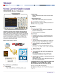
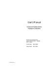
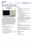
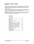
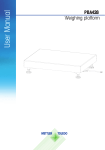
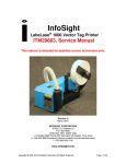
User’s Manual
1U Rack-mount RJ45
Interconnect Module
RS-232 Protocol Support using RJ45 Connectors for
PCI and SBus.
Models:
15-30007-00 Rev. A
RIM-16
RIM-32
RIM-48
Copyright © 2001, Aurora Technologies, Inc., a Carlo Gavazzi Group company.
All Rights Reserved.
Printed in the United States of America
This publication is protected by Federal Copyright Law, with all rights reserved. No part of this publication may be copied, photocopied, reproduced, stored in a retrieval system, translated, transmitted, or transcribed in any form or by any means manual, electric, electronic, electromagnetic, mechanical, optical,
or otherwise, in whole or in part without prior written consent from Aurora Technologies, Inc.
Limitation of Liability
Aurora Technologies, Inc. makes NO WARRANTY, EXPRESSED or IMPLIED, with respect to this
manual, and any related items, its quality, performance, merchantability, or fitness for any particular use.
It is solely the purchaser’s responsibility to determine its suitability for any particular use.
Information contained in this document is subject to change without notice.
Trademark Credits
Aurora Technologies, the Aurora logotype, Apollo Multiport, Nova Multiport, Aries Multiport, ControlTower, Explorer Multiport, L ANMultiServer, Saturn Multiport, SBox, Vanguard Multiport, WANMultiServer, XP7 Expansion Tower and XP-7R Rack-Mounted Expansion Unit are trademarks of Aurora
Technologies, Inc., a Carlo Gavazzi Group company.
SPARC is a registered trademark of SPARC International, Inc. in the United States and other countries.
Sun, Sun Microsystems, and Solaris are trademarks or registered trademarks of Sun Microsystems, Inc.
All other registered trademarks and salesmarks are the proprietary property of their respective owners.
Declaration of Conformity
Konformitätserklärung
Déclaration de conformité
Declaración de Confomidad
Verklaring de overeenstemming
Dichiarazione di conformità
We/Wir/Nous/Wij/Noi:
Aurora Technologies, Inc.
10 Mupac Drive
Brockton, MA 02301 USA
declare under our sole responsibility that the product,
erklären, in alleniniger Verantwortung, daß dieses Produkt,
déclarons sous notre seule responsabilité que les produit,
declaramos, bajo nuestra sola responsabilidad, que el producto,
verklaren onder onze verantwoordelijkheid, dat het product,
dichianriamo sotto nostra unica responsabilità, che il prodotto,
1U Rack-mount RJ45 Interconnect Module
to which this declaration relates is in conformity with the following standard(s) or other documents.
auf das sich diese Erklärung bezieht, mit der/den folgenden Norm(en) oder Richtlinie(n) übereinstimmt.
auquel se réfère cette déclaration est conforme à la (aux) norme(s) ou au(x) document(s) normatif(s).
al que se refiere esta declaracion es conforme a la(s) norma(s) u otro(s) documento(s) normativo(s).
waarnaar deze verklaring verwijst, aan de volende norm(en) of richtlijn(en) beantwoordt.
a cui si riferisce questa dichiarazione è conforme all/e seguente/i norma/o documento/i normativo/i.
EN 55022:1998 Class A ITE emissions requirements (EMC)
EN 6100-4-2 Electrostatic Discharge (1998)
EN 6100-4-3 Electromagnetic Susceptibility (1998)
EN 6100-4-4 EFT/Burst (1995-01)
Jim Reinhold, President
Warning
This is a Class A product. In a domestic environment this product may cause radio interference
in which case the user may be required to take adequate measures
FCC Notices
This device complies with part 15 of the FCC Rules. Operation is subject to the following two conditions: (1) This device may not cause harmful interference, and (2) this device must accept any
interference received, including interference that may cause undesired operation.
Note: this equipment has been tested and found to comply with the limits for a Class A digital
device, pursuant to part 15 of the FCC Rules. These limits are designed to provide reasonable protection against harmful interference when the equipment is operated in a commercial environment. This equipment generates, uses, and can radiate radio frequency energy and, if not installed
and used in accordance with the instruction manual, may cause harmful interference to radio
communications. Operation of this equipment in a residential area is likely to cause harmful interference in which case the user will be required to correct the interference at his own expense.
Contents
CHAPTER 1
Introduction.......................................................................................1
RIM Models .......................................................................2
Getting Help.......................................................................3
Registration........................................................................3
CHAPTER 2
Installation .........................................................................................5
Installation Precautions .....................................................5
Unpacking the RIM Model and Cables.............................6
Changing the Jumper Settings ..........................................7
Other Things You’ll Need .................................................7
Cabling ...........................................................................7
Tools ...............................................................................7
Installing the RIM Model and Cables...............................8
Assigning Port Numbers ...................................................8
CHAPTER 3
RS-232 Configurations and Descriptions ............................9
RIM Model Overview........................................................9
RS-232 Configuration .....................................................10
Nova Multiport™ 1600SE Asynchronous Mode ......11
Aries Multiport™ 16000P Serial Controller .............13
CHAPTER 4
Troubleshooting ..............................................................................15
Overview ..........................................................................15
Installation Problems .......................................................16
Post-installation Problems ..............................................17
1U Rack-mount RJ45 Interconnect Module
v
Upgrading the RIM Model ............................................. 19
Calling for Support.......................................................... 23
APPENDIX A
Warranty ........................................................................................ 25
Hardware ..................................................................... 25
Return Policy............................................................... 25
90 Day Technical Support........................................... 26
INDEX ......................................................................................................................... 27
PRODUCT INFORMATION WORKSHEET .................................................................. 28
vi
User’s Manual
CHAPTER 1
Introduction
Congratulations on purchasing your 1U Rack-mount RJ45
Interconnet Module (RIM). Aurora Technologies™ RIM models are built for today’s need for rack-mount port density. Plus,
the RIM models have been designed to expand as your business
grows with 16 RJ45 port field upgrade modules. Different models provide cabling interfaces for either PCI or SBus systems.
Other features of the RIM models include:
•
•
•
•
Offers easy and quick installation on standard 19 inch racks
Provides RS-232 protocol support
Provides up to 48 ports per 1U height
Distributes asynchronous signal transmission from
Aurora’s PCI or SBus multiport serial controller cards to
peripheral devices
• Offers field upgradeability
The specific RIM model may have 16, 32, or 48 ports using
RJ45 connector jacks, as shown in Figur e1. It is configured to
provide RS-232 protocol support. The three RIM port configurations are shown in Figure 2.
1
8
Figure 1. RJ45 Connector Jack with Pin Designation
1U Rack-mount RJ45 Interconnet Module
1
CHAPTER 1
Introduction
%""
6'%*01.1)+'5
%""
6'%*01.1)+'5
%""
6'%*01.1)+'5
Figure 2. 16, 32 and 48 port RIM Configurations
RIM Models
The following table outlines the various RIM models available
from Aurora Technologies. The difference between the models
is the number of 16 port interconnect modules, or IM-16, that
are included in the RIM chassis. Host bus specific interfacing is
contained solely in the interconnect cable.
Table 1.
RIM Models
Model
Number of Ports
Host Bus *
RIM-16
16
PCI or SBus
RIM-32
32
PCI or SBus
RIM-48
48
PCI or SBus
* Interconnect cables, which are sold separately, are bus architecture specific.
2
User’s Manual
Getting Help
Getting Help
If you need to reach us, you can contact us by
• The Web: www.auroratech.com for product literature,
phone numbers and address.
• Phone service: 888.290.9660. Mon–Fri, 8:30AM–6:00PM
Eastern Time. To expedite service, have your product serial
number and your system information available.
• FAX: Attn: Customer Service and Support
• Email: [email protected]
Registration
To receive standard warranty coverage on your Aurora product,
including 90 days of free technical support, you must complete
and mail back the Aurora Warranty Registration Card that is
located in the back of this manual. Phone support can only be
provided after product registration is complete. Extended Hardware and Software Support Agreements can be purchased to
provide additional coverage.
Sending in this card also lets us keep you up-to-date on the
complete line of Aurora Technologies’ products.
If you have any questions or comments on your Aurora Technologies’ product, contact our Customer Service and Support
Department at [email protected] or your sales
representative. ❒
1U Rack-mount RJ45 Interconnet Module
3
CHAPTER 1
4
Introduction
User’s Manual
CHAPTER 2
Installation
This chapter describes how to install the RIM models and consists of the following:
• Installation Precautions
• Unpacking the RIM Model and Cables
• Changing the Jumper Settings
• Other Things You’ll Need
• Installing the RIM Model and Cables
• Assigning Port Numbers
Note: Refer to the multiport serial controller card
user manual for installing the multiport serial controller card in the host system and for connecting
peripheral devices to the RIM model.
Before beginning the installation, record the following information in the section Product Information inside the back
cover.
• The RIM model serial number
• The Aurora Technologies multiport serial controller card
name(s) and serial number(s)
Then complete and mail the Product Registration Card/License
Application inside the back cover in order to be eligible for
technical support.
Installation Precautions
When connecting a RIM model to the Aurora Technologies’
multiport serial controller card, be sure to follow the precau-
1U Rack-mount RJ45 Interconnect Module
5
CHAPTER 2
Installation
tionary and other installation instructions found in the multiport serial controller user manual. In addition, it is important to
note the RIM model must only be used with specific Aurora
Technologies multiport serial controller cards. Connection to
other controller cards may result in damage to the unit and/or
the controller card. The RIM model is designed to interface
with RS-232 devices only. Connection to other than RS-232
devices may result in damage to the unit and/or external
device.
Unpacking the RIM Model and Cables
Before installing your RIM model, check the shipment contents
to ensure that you have all of the required parts, as listed in
Table 2. Note that the interconnect cables are sold separately
from Aurora Technologies but are required for use.
Table 2. RIM Model Parts List
Part
Quantity
RIM model (see Table 1 for model types)
1
User’s Manual with Product Registration/
Warranty Card
1
Set of Port Number Labels (9 labels)
1
Set of Rack Mount Hardware (Phillips
Screws (4) and Nuts (4)
1
Cable (PCI or SBus)
*
* Sold separately. Cable type varies with RIM model type.
Note: Save the shipping carton and the internal
packaging. If you need to ship the product back to
your dealer, you must use the original carton and
packaging.
6
User’s Manual
Changing the Jumper Settings
Changing the Jumper Settings
Each IM-16 embedded in the RIM model contains jumpers that
are used for certain wiring configurations. Prior to installing
your RIM model, you may want to consider changing its configuration. To configure the RIM model for its various modes
of operation, you must remove the Phillips head screws located
on the sides and take apart the two sections. Chapter 3 describes
the various options available and their jumper configurations.
Each system is shipped with default settings, so verify your
configuration requirements before you open the RIM chassis.
Other Things You’ll Need
To ensure a smooth installation, you should have the proper
cables and tools on hand.
Cabling
Besides the PCI or SBus interconnect cable(s) that connect the
multiport serial I/O controller to each IM-16 of the RIM
model, you need cables that connect to your peripheral device.
There are a number of cabling approaches you can use to connect devices to the new Aurora ports. Cabling to your peripheral devices is customer specific. Please call Customer Service
and Support to assist in defining your cabling needs. In addition, you may find Chapter 3 helpful for descriptions on various pin signals. For optimal performance shielded twisted pair
cables are suggested.
Tools
You’ll need the following tools to install your RIM model:
• A slot head screwdriver to make cable connections and
secure mounting screws.
• A phillips head screwdriver to fasten the RIM chassis to the
cabinet rack.
1U Rack-mount RJ45 Interconnect Module
7
CHAPTER 2
Installation
Installing the RIM Model and Cables
Before using the RIM model be sure you have the proper interconnect cable(s). These cables are sold separately from Aurora
Technologies. You should have a cable for each 16 port module
in the RIM model. Two types of cables may be used, one for
SBus multiport serial controllers or PCI multiport serial controllers.
✐ To Install the RIM Chassis to the Rack
1. For all cables that need to be connected, secure the cable
coming from the multiport serial controller to each IM-16 of
the RIM model using a slot head screwdriver. Use the connector labelled Controller to connect to the controller card
and the connector labelled RIM to connect to the IM-16.
2. Be sure to retain the order of module connections. Port label
numbers are defined by the multiport serial controller card
and device driver.
3. Using the four phillips screws and nuts provided, attach the
RIM chassis to the cabinet rack. The screw holes in the RIM
chassis should be aligned with the holes in the rack.
4. Optionally place desired port number label(s) on the face of
the RIM chassis to identify each block of 16 ports per module. Refer to the section, Assigning Port Numbers for
further assistance.
5. You may now connect your peripheral devices to ports of the
RIM model. For optimal performance shielded twisted pair
cables are suggested.
Assigning Port Numbers
Provided in the packing carton are port labels to record the RIM
port number scheme. The port number scheme, in multiples of
16 ports, is defined by the installed Aurora multiport serial
controller cards and their software device driver. Your Aurora
Technologies multiport serial controller card documentation
explains how the ports are numbered and any special considerations you should note. ❒
8
User’s Manual
CHAPTER 3
RS-232 Configurations
and Descriptions
The following sections describe the various configuration
options, and their jumper settings. Find the particular setting
that you need and set the jumpers accordingly. Note that each
module has factory default settings. Determine your needs
before you open the RIM chassis.
RIM Model Overview
Figure 2 on page 2 shows the various configurations available
in the RS-232 options. Each RIM model has one, two or three
IM-16 interconnect modules. Each IM-16 consists of a circuit
board, RJ45 connector block, and requires an interconnect cable.
Set the configuration jumpers on each board for the protocols
or equipment you plan to attach to it.
Figure 3 provides an overview of the module card and its
jumper locations for each IM-16.
1U Rack-mount RJ45 Interconnect Module
9
CHAPTER 3
RS-232 Configurations and Descriptions
Figure 3. Breakout Module Jumper Locations
RS-232 Configuration
The RIM RS-232 configuration is factory-shipped in a default
jumper configuration. The following sections describe the
default and optional jumper configurations for all models.
10
User’s Manual
RS-232 Configuration
Nova Multiport™ 1600SE Asynchronous Mode
The Nova Multiport 1600SE is a 16 port SBus multiport serial
controller of which 12 ports (0 through 11) support the full set
of modem controls (DTR, CD, CTS, RTS). It also has four ports
(12 through 15) which have two modem signalling options,
CD/DTR or RTS/CTS.
Table 3. Nova Mulitport 1600SE Pin Signals for ports 0 to 11 for Full
Modem Signalling
Pin
Signal
1
RTS
2
DTR
3
TXD
4
CD
5
RXD
6
GND
7
-
8
CTS
Factory configuration is shown in Figure 4. Jumper
block P1 is set for CTS with all jumpers connecting
Row A with Row B. Jumper block P2 is set for RTS with
the first four jumpers connecting Row A with Row B
and the remaining four jumpers set for DTR connecting Row B with Row C. Jumper block P3 is set for RTS
with all jumpers connecting Row A with Row B.
Jumper block P4 is set for CTS with the first four jumpers connecting Row A with Row B and the remaining
four jumpers set for CD connecting Row B with Row C.
In the factory set configuration, ports 0 through 11
provide full modem signalling. See Table 3 for signal
pinouts. Ports 12 through 15 provide CD/DTR control
signalling. Signal pinouts for ports 12 through 15 are
shown in Table 4.
1U Rack-mount RJ45 Interconnect Module
11
CHAPTER 3
RS-232 Configurations and Descriptions
Note: All ports do not have the full set of modem signalling. The default configuration provides the CD/
DTR setting. If you need to configure the RTS/CTS
setting, refer to the section, Optional RTS/CTS Jumpers on pag e13.
Port 8
Port 0
Port 15
DTR
C
B
A
RTS
Port 7
DTR
C
B
A
RTS
P3
P2
Port 0
Port 8
Port 7
CD
C
B
A
CTS
Port 15
CD
C
B
A
CTS
P4
P1
Figure 4. 1600SE Default Jumper Settings
Table 4. 1600SE RS-232 Asynchronous Pin Signals for ports 12 to 15,
CD/DTR
12
User’s Manual
Pin
Signal
2
DTR
3
TxD
4
CD
5
RxD
6
SIG GND
RS-232 Configuration
To configure ports 12 through 15 for RTS/CTS signalling, set the jumpers as shown in Figure 5 and described
in Table 5.
Port 8
Port 15
C
B
A
DTR
RTS
P2
Port 8
Port 15
CD
C
B
A
CTS
P4
Figure 5. 1600SE RTS/CTS Jumpers
Table 5. 1600SE RS-232 Asynchronous Pin Signals, RTS/CTS
Pin
Signal
1
RTS
3
TxD
5
RxD
6
SIG GND
8
CTS
Aries Multiport™ 16000P Serial Controller
The Aries Multiport 16000P is a PCI multiport serial controller
that supports the full set of modem lines (RTS, CTS, DTR and
CD). Jumpers should be left in the default factory setting as pictured in Figure 6. All jumpers are set for RTS and CTS connecting Row A with Row B. Please note to accommodate the full 16
ports, there are two 8-port jumper arrays for setting CTS
1U Rack-mount RJ45 Interconnect Module
13
CHAPTER 3
RS-232 Configurations and Descriptions
(marked P1 and P4) and two 8-port jumper arrays setting RTS
(marked P2 and P3).
Port 8
Port 0
Port 15
DTR
C
B
A
RTS
Port 7
DTR
C
B
A
RTS
P3
P2
Port 0
Port 8
Port 7
CD
C
B
A
CTS
Port 15
CD
C
B
A
CTS
P4
P1
Figure 6. Default Jumper Settings for Aries 16000P
Table 6 below lists the pinouts for the Aries 16000P.
Table 6. Aries Mulitport 16000P Pin Signals for all ports for Full
Modem Signalling
Pin
❒
14
User’s Manual
Signal
1
RTS
2
DTR
3
TXD
4
CD
5
RXD
6
GND
7
-
8
CTS
CHAPTER 4
Troubleshooting
This chapter describes problems you could possibly experience
with your RIM model and the actions you should take to diagnose and solve the problem. Topics covered in this chapter
include:
•
•
•
•
•
Overview
Installation Problems
Post-installation Problems
Upgrading the RIM Model
Calling for Support
Overview
The RIM models are simple to test and troubleshoot. A RIM
unit is comprised of one, two, or three 16 port interconnect
assemblies in a rack mount sheet metal box. These assemblies,
or interconnect modules (IM-16), connect to Aurora serial controller cards using either a 96 or 100 conductor interface cable,
depending on the bus of the host computer.
A 96 conductor cable is used for Aurora SBus multiport serial I/
O card, Nova Multiport 1600SE, and a 100 conductor cable is
used for Aurora PCI bus multiport serial I/O card, Aries Multiport 16000P. Figure 7 shows a typical RIM configuration.
1U Rack-mount RJ45 Interconnect Module
15
CHAPTER 4
Troubleshooting
RIM Assembly
Interconnect Cables (3)
Ports 32-47
Ports 32-47
Ports 16-31
Ports 16-31
Ports 0-15
16 Port Modules
Host System w/3 Serial Cards
Ports 0-15
Figure 7. A Typical RIM Configuration
Installation Problems
If you experience problems immediately after installing your
RIM model, check the following list of potential problems.
• Is the interconnect cable between the controller card and
each IM-16 properly connected. Check for loose
connections.
• Is the peripheral device cable the correct type? If it is a nullmodem cable is it the right kind of null-modem cable?
The vast majority of problems are due to incorrect cable
selection.
• Are any connections to other boards loose?
• Is the I/O serial controller card properly seated in the
system?
• Are the external equipment connections made properly?
16
User’s Manual
Post-installation Problems
• If you are experiencing interference, are you using properly
shielded cables?
Make sure that the cabling is not running near a power
source; if it is, try moving the cabling to a new location.
• Is the peripheral device cable length correct?
The RS-232 cable specification is 75 feet at 9.6 Kbps. However, this is a nominal length defined by the standard, and it
is possible to use longer cables up to 30 meters, with lowcapacitance cables, or with slow data rates and a proper error
correction mechanism.
• If the problem remains after these checks, remove
• the Aurora device driver software (see “Remove Existing
Aurora Drivers” in the Driver Release Notes).
• the multiport controller card (see your SPARC™ or x86
system hardware documentation for instructions).
Next, re-test your system to determine whether it operates correctly. If it does, the problem may be with the controller card,
interconnect cable or RIM model. If it does not, the problem is
most likely with the system including the cable connecting the
peripheral device. Please refer to the user manual of the multiport serial I/O card and the peripheral device for more assistance.
Post-installation Problems
The most likely causes of malfunction after installation are:
• Incorrect jumper setting.
• Improper interface cable installation.
• Multiport serial controller card not installed correctly.
Review the appropriate section(s) of this user manual and the
multiport I/O serial controller manual before proceeding.
1U Rack-mount RJ45 Interconnect Module
17
CHAPTER 4
Troubleshooting
✐ If all of the above items have been checked, perform the
following:
1. Insert a loopback test plug into the malfunctioning port on
the IM-16.
2. Run a TIP loopback test on the corresponding port.
3. If the test fails, there may be a problem related to the IM-16,
the interface cable or the serial card.
4. If the RIM model has more than one IM-16, exchange the
interface cable with one from a different IM-16 or with a
replacement cable and retest. If the port operated properly,
then the cable is the failed component.
5. If the port still fails, the problem is related to either the IM-
16 or the serial controller card. To ascertain which component is at fault, exchange the cables as shown in Figure 8.
6. Note that the port locations will change if the cables are
swapped. For example, if the failed port is port 0, that port
will be in the second 16 port group. Move the loopback plug
to the matching port location in the new group. For example,
if port 0 originally failed, the loopback would be moved to
port 16 after swapping the cables. Retest the same port
number (port 0 per the example). If the port still fails, the
problem is the serial controller card. If it functions normally,
the first IM-16 is the defective item. Replacements can be
obtained from Aurora.
18
User’s Manual
Upgrading the RIM Model
RIM Assembly
Interconnect Cables (3)
Ports 32-47
Ports 32-47
Ports 16-31
Ports 0-15
Ports 0-15
16 Port Modules
Host System w/3 Serial Cards
Ports 16-31
Figure 8. Cables Swapped
Upgrading the RIM Model
Employing IM-16 modules, each RIM model has been designed
to be field upgradeable. In the event that an IM-16 needs to be
replaced follow the procedures below to Gain Access to the
RIM chassis and Remove an existing IM-16. Then follow the
instructions to Add an IM-16 replacement.
In the event an additional IM-16 is to be installed into an available slot of the RIM chassis, follow the procedures to Gain
Access to the RIM chassis and then Add an IM-16.
✐ Gain Access to the RIM chassis
1. Remove the screws that secure the RIM chassis to the rack
cabinet.
1U Rack-mount RJ45 Interconnect Module
19
CHAPTER 4
Troubleshooting
2. Either remove the RIM chassis from the rack or slide it out
far enough to gain access to the screws securing the top
cover (Figure 9).
3. If necessary, disconnect the interconnect cable(s) from the
rear of the unit. Cables should only be removed when the
host workstation is powered down.
4. Remove the 12 phillips screws securing the top cover.
5. Remove the top cover.
6. Remove the four screws along the bottom edge of the front
panel, then remove the panel (Figure 10).
Figure 9. Removing or Installing the RIM Chassis Cover
Figure 10. Installing or Removing the RIM Chassis Front Panel
20
User’s Manual
Upgrading the RIM Model
✐ Remove an existing IM-16
1. Follow the instructions above to Gain Access to the RIM
chassis.
2. Remove the four phillips mounting screws and the two jack-
screws securing the IM-16 to the RIM chassis and remove
the module. (Figure 11).
✐ Add an IM-16
1. Follow the instructions above to Gain Access to the RIM
chassis.
2. If you are replacing an IM-16, skip to the next step. If you
are adding a new IM-16, you must first remove the front
and rear filler plates from the RIM chassis for the slot where
you want to place the IM-16. The filler plate must be
removed from inside of the panel. Remove the two hex nuts
used to secure the front filler plate. See Figure 12. Also,
remove the two phillips screws to remove the rear filler
plate.
3. Check the jumper settings on the new IM-16. Jumper set-
tings are described in Chapter 3.
4. Place the new IM-16 in the RIM chassis and align the four
holes with the mounting standoffs.
5. Attach the new IM-16 to the desired slot of the RIM chassis
with the four mounting phillips screws and two jackscrews
that came in the shipping box. Refer to Figure 11. The jackscrews require a 3/16 inch nutdriver.
6. Replace the panel by securing it with the four original
screws along the bottom edge of the front panel.
7. Replace the top cover and secure with the original 12 phillips
screws.
1U Rack-mount RJ45 Interconnect Module
21
CHAPTER 4
Troubleshooting
8. You may need to re-connect the interconnect cables going to
the existing IM-16 module(s). Connect the new interconnect cable from the IM-16 to the multiport serial I/O
controller. Be sure the host workstation is powered off.
9. Slide the RIM chassis into the rack and attach with the orig-
inal four screws.
10. Apply the appropriate port labels to the front panel to iden-
tify the new ports.
11. Connect your peripheral devices. For optimal performance
shielded twisted pair cables are suggested.
Jack Screws (2)
Mounting Screws (4)
Figure 11. Installing or Removing an IM-16
Front Panel
R e m o v e n u ts a n d fille r p la te
Figure 12. Filler plate for middle IM-16 slot
22
User’s Manual
Calling for Support
Calling for Support
In the event you need to call Aurora Technologies’ for technical
support, make sure you have completed the following checklist:
1. RIM Model Serial Number:
______________________________
(found in the back of this manual, on the board, and on the
shipping container)
2. SPARC™ or x86 system model
number: _________________
3. Solaris™ version: _________________________________
4. List all peripherals connected to the RIM model.
5. Multiport Controller
software driver version: _____________________________
(The version number is printed on the driver software media
and is displayed when installation is completed.)
6. List the cable pinout description.
7. Verify the type of device cables used. (modem, null-modem,
etc.)
Customer Service and Support is available at 888.290.9660 Monday through Friday, 8:30AM to 6:00PM Eastern Time. In addition,
e-mail may be sent to [email protected]. ❒
1U Rack-mount RJ45 Interconnect Module
23
CHAPTER 4
24
Troubleshooting
User’s Manual
APPENDIX A
Warranty
Hardware
All Aurora Technologies, Inc. hardware products are warranted against defects
for two years from the date of delivery. Buyer agrees that if this product proves
defective, Aurora Technologies, Inc. is obligated only to repair, replace or refund the purchase of this product at Aurora Technologies, Inc.’s discretion. The
warranty is void if the product has been subjected to alteration, neglect, misuse
or abuse; if any repairs have been attempted by anyone other than Aurora
Technologies, Inc.; or if failure is caused by accident, acts of God, or other causes beyond the control of Aurora Technologies, Inc.
Aurora Technologies, Inc. reserves the right to make changes or improvements
in any product without incurring any obligation to similarly alter products
previously purchased. In no event shall Aurora technologies, Inc. be liable for
any direct, indirect, incidental or consequential damages arising out of or in
connection with the performance or use of the product or information provided. Aurora Technologies, Inc.’s liability shall in no event exceed the purchase
price of the product purchased hereunder.
The foregoing limitation of liability shall be equally applicable to any service
provided by Aurora Technologies, Inc.
Return Policy
Products returned for repair must be accompanied by a Return Material Authorization (RMA) number, obtained from Aurora Technologies, Inc. prior to
return. Freight on all returned items must be prepaid by the customer, and the
customer is responsible for any loss or damage caused by common carrier in
transit. Items will be returned to Aurora Technologies, Inc. via a Customs
cleared carrier (for example, Federal Express, UPS, DHL), unless prior arrangements are made by the customer for an alternative shipping method. Each
product that is returned for repair must include a failure report and must have
the RMA number clearly marked on the outside packaging.
Return Address:
Attn.: RMA Department
Aurora Technologies, Inc.
646 Summer Street
Brockton, MA 02302
USA
1U Rack-mount RJ45 Interconnect Module
25
APPENDIX A Warranty
90 Day Technical Support
Products must be registered with Aurora Technologies, Inc.’s Customer Service and Support (CSS) organization to receive the 90 Day Technical Support.
You must fill out and mail or FAX the warranty card that is included with the
product before receiving technical assistance.
What you get during the 90 Day Techni
hnical Sup
Support
90 Day Technical Support is provided by e-mail, FAX, or by telephone. Customers calling in for technical support on current Aurora technologies, Inc.
products will receive a response within four (4) business hours. Customer’s emails or faxed requests will receive a response within twenty-four (24) business hours.
The Technical Support hours in Massachusetts are
8:30 a.m. - 6:00 p.m. Eastern Time,
Monday through Friday, excluding holidays.
Services provided under the 90 Day Technical Support Plan are:
• Help on installation and configuration
• Help diagnosing problems with Aurora hardware and standard released
Aurora device drivers.
• Help navigating and locating existing Aurora documentation
• Acceptance of bug reports and providing status updates on any applicable
bug fixes.
Policies and pricing are subject to change without notice.
For extended support, please refer to the Aurora Technologies, Inc. web site at
www.auroratech.com or call your Sales representative for detail s.❒
26
User’s Manual
Index
A
P
Aries Multiport 16000P 13
Parts List 6
PCI 1, 15
Performance levels 1
C
Port Numbers 8
Calling for support 23
Product Information
Worksheet 28
Customer Service and
Support
contacting 3, 23
R
Registration 3
G
RS-232 Configuration 10–14
Getting help 3
S
I
SBus 1, 15
Installation 5–8
problems 16
Serial card, unpacking 6
Support 3
J
T
Jumper Settings 7, 13
Troubleshooting 15–23
N
Nova Multiport 1600SE 11–13
W
Warranty 25–26
1U Rack-mount RJ45 Interconnect Module
27
Product Information Worksheet
Please record the following data about your Aurora 1U Rackmount RJ45 Interconnect Module and multiport serial controller
card:
RIM Model Serial umber: _______________________________
Multiport Serial Controller Model: ________________________
Multiport Serial Controller
Card Serial Number: ___________________________________
Connected peripherals by port number (copy sheets as needed):
Port No.
28
User’s Manual
Peripheral