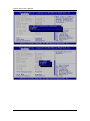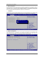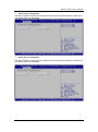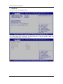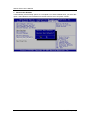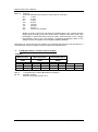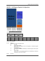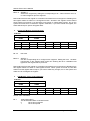
1
NA570 Series SMB Network Appliance User’s Manual Disclaimers This manual has been carefully checked and believed to contain accurate information. Axiomtek Co., Ltd. assumes no responsibility for any infringements of patents or any third party’s rights, and any liability arising from such use. Axiomtek does not warrant or assume any legal liability or responsibility for the accuracy, completeness or usefulness of any information in this document. Axiomtek does not make any commitment to update the information in this manual. Axiomtek reserves the right to change or revise this document and/or product at any time without notice. No part of this document may be reproduced, stored in a retrieval system, or transmitted, in any form or by any means, electronic, mechanical, photocopying, recording, or otherwise, without the prior written permission of Axiomtek Co., Ltd. CAUTION If you replace wrong batteries, it causes the danger of explosion. It is recommended by the manufacturer that you follow the manufacturer’s instructions to only replace the same or equivalent type of battery, and dispose of used ones. Copyright 2014 Axiomtek Co., Ltd. All Rights Reserved Dec 2014, Version A3 Printed in Taiwan ii Safety Approvals CE Marking FCC Class A FCC Compliance This equipment has been tested and complies with the limits for a Class A digital device, pursuant to Part 15 of the FCC Rules. These limits are designed to provide reasonable protection against harmful interference in a residential installation. If not installed and used in accordance with proper instructions, this equipment might generate or radiate radio frequency energy and cause harmful interference to radio communications. However, there is no guarantee that interference will not occur in a particular installation. If this equipment does cause harmful interference to radio or television reception, which can be determined by turning the equipment off and on, the user is encouraged to try to correct the interference by one or more of the following measurers: Reorient or relocate the receiving antenna. Increase the separation between the equipment and receiver. Connect the equipment into an outlet on a circuit different from that to which the receiver is connected. Consult the dealer or an experienced radio/TV technician for help. Shielded interface cables must be used in order to comply with emission limits. iii Safety Precautions Before getting started, read the following important cautions. 1. Be sure to ground yourself to prevent static charge when installing the internal components. Use a grounding wrist strap and place all electronic components in any static-shielded devices. Most electronic components are sensitive to static electrical charge. 2. Disconnect the power cords from the NA570 Series before making any installation. Be sure both the system and the external devices are turned OFF. Sudden surge of power could ruin sensitive components. Make sure the NA570 Series is properly grounded. 3. Do not open the system’s top cover. If opening the cover for maintenance is a must, only a trained technician is allowed to do so. Integrated circuits on computer boards are sensitive to static electricity. To avoid damaging chips from electrostatic discharge, observe the following precautions: Before handling a board or integrated circuit, touch an unpainted portion of the system unit chassis for a few seconds. This will help to discharge any static electricity on your body. When handling boards and components, wear a wrist-grounding strap, available from most electronic component stores. Trademarks Acknowledgments Axiomtek is a trademark of Axiomtek Co., Ltd. ® Windows is a trademark of Microsoft Corporation. IBM, PC/AT, PS/2, VGA are trademarks of International Business Machines Corporation. ® ® Intel and Pentium are trademarks of Intel Corporation. AMI is trademark of American Megatrend Inc. Other brand names and trademarks are the properties and registered brands of their respective owners. iv Table of Contents Disclaimers ..................................................................................................... ii Safety Approvals ........................................................................................... iii Safety Precautions ........................................................................................ iv Chapter 1 Introduction .......................................... 1 1.1 General Description ............................................................................ 1 1.2 Features ............................................................................................... 1 1.3 Specifications ...................................................................................... 2 1.4 Dimensions and Outlines ................................................................... 5 1.5 I/O Outlets ............................................................................................ 6 1.5.1 1.5.2 Chapter 2 Front Panel .................................................................................................. 6 Rear Panel .................................................................................................. 8 Hardware and Installation .................... 9 2.1 Check List ............................................................................................ 9 2.2 Board Layout ..................................................................................... 10 2.3 Jumper Settings ................................................................................ 12 2.3.1 2.3.2 2.3.3 2.3.4 2.4 Connectors ........................................................................................ 15 2.4.1 2.4.2 2.4.3 2.4.4 2.4.5 2.4.6 2.4.7 2.4.8 2.4.9 2.4.10 2.4.11 2.5 LAN Bypass Control Selection Jumper (JP1, JP2, JP3) ........................... 13 Auto Power Button Model Jumper (JP5) ................................................... 13 TM Compact Flash Voltage Selection Jumper (JP6) ................................... 14 CMOS Clear Jumper (JP7) ....................................................................... 14 LCM Power Connector (LCM1) ................................................................. 16 TPM Module Connector (TPM1) ............................................................... 16 Front Panel Bezel Connector (CN1) ......................................................... 17 Serial Port1 & USB3.0 Port1/2 Connector (CN11) .................................... 18 ATX Power Connector (CN12) .................................................................. 18 ATX +12V CPU Power Connector (ATX1) ................................................ 19 Serial ATA Connectors (SATA1.2) ............................................................. 19 USB Port Connectors (USB1) ................................................................... 19 Compact Flash™ Socket (CF1) ................................................................ 20 Serial Port 2 Connector (COM2) ............................................................... 21 FAN Connector (FAN1.FAN2) ................................................................... 21 Hardware Installation ........................................................................ 22 2.5.1 2.5.2 2.5.3 Installing the CPU ...................................................................................... 22 Installing the Memory ................................................................................ 25 Installing the Hard Disks............................................................................ 26 v 2.5.4 Installing the LAN modules ....................................................................... 27 Chapter 3 AMI BIOS Setup Utility ........................ 29 3.1 Starting ............................................................................................... 29 3.2 Navigation Keys ................................................................................ 29 3.3 Main Menu.......................................................................................... 30 3.4 Advanced Menu ................................................................................. 31 3.5 Chipset Menu ..................................................................................... 42 3.6 Boot Menu.......................................................................................... 45 3.7 Security Menu .................................................................................... 47 3.8 Save & Exit Menu .............................................................................. 48 Appendix A LAN Bypass Configuration .................. 53 Appendix B WDT Timer for System Reset .............. 61 Appendix C LAN Module Expansion ....................... 63 Appendix D Warning ............................................... 73 vi NA570 Series User’s Manual Chapter 1 Introduction This chapter contains general information and detailed specifications of the NA570 Series Network Appliance Server. It contains the following sections: General Description Features Specifications Dimensions and Outlines I/O Outlets 1.1 General Description th The NA570 is a 1U rackmount network appliance based on the 4 Generation Intel® Xeon E3/ Core i Processors with Intel® C226/H81 Chipset (Haswell), The appliance sets the target at greatly improved CPU performance and reduced power consumption based on Intel’s new architecture. It provides greater performance and power efficiency to equipment providers. The Intel® AES New Instruction (AES-NI) enhancements are included with the NA570; hardware-based acceleration to encrypt/decrypt the data. And it also support the Intel® Data Plane Development Kit (Intel® DPDK), a set of software libraries that can improve packet processing performance by up to ten times. It can achieve over 80 Mbps throughput on a single Intel® Xeon processor. For greater flexibility, the NA570 has two front-accessible expansion slots that allow developers to expand one different LAN modules based on their solution requirements. This expansions need to be requested before production. The 2 expandable LAN modules via the PCIe 3.0 interface, supporting up to 24 GbE ports or up to 4 10GbE ports. To avoid the influences of shutdown by the environment, the NA570 supports data protection via 12 pairs of latch-type LAN bypass for fail-over option. For storing event log data, the NA570 utilizes two 2.5” SATA HDDs or one 3.5” SATA HDD. And NA570 supports two dual channel up to 32GB DDR3-1600 non-ECC/ECC memory and one standard PCIe x8 expansion slot for optional network security card. The NA570 is designed for network enterprise business. NA570 not only provides high performance processor, memory, storage interface and LAN connection, but also includes outstanding management capability. 1.2 Features th LGA1150 Intel® 4 Generation processor Two to four DIMM sockets, up to 32GB none-buffer none-ECC / ECC memory (DDR3 1600) Supports Two LAN modules expansion (NA570 optional) Supports BIOS redirected to COM port Supports two 2.5” SATA HDDs or one 3.5” SATA HDD (optional) Suitable for VPN, network bandwidth controller, firewall applications Introduction 1 NA570 Series User’s Manual 1.3 Specifications System System CPU th Intel® 4 Generation Xeon® E3 (only NA570) / Core I processors System Chipset NA570: Intel® C226 PCH NA570L: Intel® H81 PCH System Memory NA570: 4 x DDR3 1600 DIMM sockets, up to 32GB none-buffer none-ECC / ECC memory NA570L: 2 x DDR3 1600 DIMM sockets, up to 16GB none-buffer none-ECC memory BIOS AMI 64Mbit PnP Flash BIOS with function of BIOS redirected to COM port HDD Interface Two 2.5” SATA HDDs or one 3.5” SATA HDD (optional) LAN The default is 8 10/100/1000Mbps LAN ports and 2 pairs LAN bypass. NA570: Expandable up to 24 LAN ports via LAN modules and 12 pairs LAN bypass. NA570L: Expandable up to 16 LAN ports via LAN modules and 8 pairs LAN bypass. LAN Modules Slim Module Ports Chipset Bypass NA570 NA552 AX93316-8GI 8 Intel 82580EB 0 v v AX93316-8GIL 8 Intel 82580EB 4 v v AX93336-4GI-i210 4 Intel i210AT 2 v v AX93336-4GI-i350 4 Intel i350 2 v v GbE Copper Modules GbE Fiber Modules AX93322-8FI 8 Intel 82580EB 0 v v 4+4 Intel 82580EB 2 v v 4 Intel i350 0 v v 2 Intel X540 1 v v AX93307-2FI 2 Intel 82599ES 0 v v AX93307-2FIL 2 Intel 82599ES 1 v v AX93322-8MIL AX93336-4FI-i350 10GbE Copper Modules AX93317-2GIL 10GbE Fiber Modules Flash One CF socket Super I/O Controller: Winbond NCT6102D Serial Ports: Totally 2 asynchronous ports (2 x RS-232; one is 10-pin header onboard, the other one is RJ-type connector with Cisco define) 2 Introduction NA570 Series User’s Manual I/O Interface One console RJ-type connector, 2 USB 3.0 connectors and 8 RJ-45 connectors (default) or up to 24 LAN ports (expandable). LED: 1x4 LED for LAN bypass 1~4 From top to bottom (default will be 2 LED only) 2 x LAN modules (optional) AX98706 LED board: 1 x 4 LED for Power、HDD、GPIO1、GPIO2 Tact switch x2 (Left : GPIO/software reset )、(right: hardware system reset button ) Watchdog Timer One for System Reset: 255 levels, 1-255 sec LAN Modules for LAN bypass: 7 levels, 1-64 sec USB Two USB 3.0 ports one front side, two USB 2.0 are internal pin headers (NA570) Hardware Monitoring Controller Winbond NCT6102D CPU temperature, system temperature, power and fan speed detection Expansion Slot One external PCIe slot (optional by AX98611 expansion card and AX96708 Riser bracket) Limitation: The PCIe devices are total 12 devices. Therefore user should check how many LAN chip configuration are installed in NA570/NA570L. Other Features NA570 supports two front-accessible expansion slot allows our customers to configure different LAN modules based on their solution requirements before production. It provides copper and fiber modules, up to 12 groups LAN bypass for option.(AX98611 for 1pcs LAN module and PCIe x 8 slot / AX98612 for 2pcs LAN modules) NA570L supports one front-accessible expansion slot allows our customers to configure optional LAN module based on their solution requirements before production. It provides copper and fiber modules, up to 8 groups LAN bypass for option. (AX98611 for 1pcs LAN module or AX98610 for 1 x PCIe x 8 slot.) Power Supply 270W single power supply 1U 200W redundant power supply (NA570 optional) Note: Indicates to unplug all AC power cord(s) to disconnect AC Power OS Compatibility Linux Mechanical/Environmental Form Factor 1U rackmount LED Power, HDD, GPIO LEDs, LAN bypass LEDs Operation Temperature 0°C ~ 40°C (32°F ~ 104°F) Introduction 3 NA570 Series User’s Manual Storage Temperature -20°C ~ 85°C (-4°F ~ 185°F) Humidity 10% - 95% RH, non-condensing Chassis Material Steel Dimensions 44mm (1.73”) (H) x 430mm (16.84”) (W) x 450mm (20.59”) (D) Certificate FCC class A / CE class A Note: 4 All specifications and images are subject to change without notice. Introduction NA570 Series User’s Manual 1.4 Dimensions and Outlines The following diagram shows you dimensions and outlines of the NA570 Series. Default: 8 LAN ports Introduction Expandable up to 24 LAN ports 5 NA570 Series User’s Manual 1.5 I/O Outlets Locate front and rear panel I/O outlets on the NA570 Series server to connect serial and ethernet interface devices. 1.5.1 6 Front Panel Power LED (Green) LED light up when the server is powered on to perform diagnostic tests and proper operation checking. HDD LED (Green) LED flashes when HDD is transmitting or receiving data. Programmable LED GPIO1, GPIO2 (Green) The GPIO1 and GPIO2 LEDs are controlled by programmable GPIO. A sample code will be provided that allow users to define their own function. The sample codes for the above features can be found in the CD, and they are only for customers’ reference as remarked. “Default” Tact Switch (Left) The sample code will be provided that allows users to define their own function. For example, when the system has any problems, this switch can support to reset it to the customer’s OS default settings if our customer’s OS supports this application. “Reset” Tact Switch (Right) It is for reset the system to reboot your computer instead of turning OFF the power switch. It is a better way to reboot your system for a longer life of the system’s power supply. Console Port This is a Cisco RJ-type connector console port for command line interface and diagnostic support by P.O.S.T (Power On Self Test). USB1.2 Ports Two USB 3.0 ports supported. LAN bypass LED While running the LAN By-Pass function, the LED always lights up. Introduction NA570 Series User’s Manual Transfer Rate for LAN port The double-color LED light indicates 10/100/1000Mbps transfer rate. LED Light Color Transfer Rate Dark 10Mbps Green 100Mbps Orange 1000Mbps If the LED is dark and Active/Link LED is lighting on flashing, the transfer rate should be 10Mbps. When the green-color LED light is radiating, the transfer rate should be 100Mbps. When the orange-color LED light is radiating, the transfer rate should be 1000Mbps. When this LED and Link/Active LED both are dark, no networking devices are attached. Active/Link LED for LAN Port The orange LED is on when the LAN port connection is working. The LED flashes when transmitting or receiving any signals to or from the appliance. The LED is dark when the appliance is off. Note: Introduction Optional LAN module LED definition in Appendix C. 7 NA570 Series User’s Manual 1.5.2 8 Rear Panel Power Supply System power use power cord to connect the power supply to electrical outlet (AC). System Fan These are fans for cooling down system temperature. Introduction NA570 Series User’s Manual Chapter 2 Hardware and Installation The NA570 Series are convenient for your various hardware configurations. This chapter will help you get familiar with the hardware. 2.1 Check List The package bundled with your NA570 Series should contain the following items: The NA570 Series network appliance hardware platform Power cord x 1 Utility CD (including user’s manual and sample code) Mounting brackets for rack installation (left/right) x 2 Plastic stand for stack–up x 4 Mounting screws for disk drive and additional screws for this appliance’s spare parts SATA II cable x 2 for 2.5” SATA HDDs If you can not find this package or any items are missing, please contact Axiomtek distributors immediately. If you order any optional components, the package might contain those additional hardware or documents accordingly. Hardware and Installation 9 NA570 Series User’s Manual 2.2 Board Layout TOP 10 Hardware and Installation NA570 Series User’s Manual BOTTOM Hardware and Installation 11 NA570 Series User’s Manual 2.3 Jumper Settings Jumper is a small component consists of jumper clip and jumper pins. Install jumper clip on 2 jumper pins to close. And remove jumper clip from 2 jumper pins to open. Below illustration shows how to set up jumper. This section provides the information about jumpers and connectors of NA570 Series. Properly configure jumper settings on the main board in this appliance to meet your application purpose. Below we list a summary table of all jumpers and default settings for onboard devices. Jumper Definition Jumper Setting (1-2)/(1-2)/(1-2): JP1 JP2 JP3 LAN Bypass Trigger When Power On Mother board/SEGN1 ~4 Bypass as same as Power Off status (1-2)/(1-2)/(2-3): Mother board/SEGN1~4 Bypass Disable(Default) (1-2)/(2-3)/(2-3): Mother board/SEGN1 ~4 Bypass Enable JP5 12 Auto Power Button Mode Selection TM 1-2:Always Off 2-3:Always On (Default) Voltage 1-2:+3.3V (Default) 2-3:+5V JP6 Compact Flash Selection JP7 Clear CMOS Setting 1-2:Normal (Default) 2-3:Clear CMOS Hardware and Installation NA570 Series User’s Manual 2.3.1 LAN Bypass Control Selection Jumper (JP1, JP2, JP3) Description Function Jumper Setting JP1 JP2 JP3 JP1 JP2 JP3 JP1 JP2 JP3 Mother board/SEGN1 ~4 Bypass as same as Power Off status LAN Bypass Trigger when Power On Mother board/SEGN1 ~4 Bypass Disable(Default) Mother board/SEGN1 ~4 Bypass Enable Note: When the system is turned on, you can select LAN bypass function by Jumper and Bios when power on state, when enter the OS, you can select LAN pass function at power on/ off state by software. 2.3.2 Auto Power Button Model Jumper (JP5) Description Function Always Power Off ATX Mode Auto Power Button Mode Selection Always Power On (Default) Hardware and Installation Jumper Setting JP5 JP5 13 NA570 Series User’s Manual 2.3.3 Compact FlashTM Voltage Selection Jumper (JP6) Description Function Jumper Setting JP6 +3.3V (Default) TM Compact Flash Voltage Selection JP6 +5V 2.3.4 CMOS Clear Jumper (JP7) Use this jumper to erase and restore CMOS memory and BIOS setting. Put jumper clip to pin 2-3 for a few seconds then move it back to pin 1-2. By doing this procedure CMOS data resets to its safe default settings. Description Function Jumper Setting JP7 Normal (Default) COMS Clear JP7 Clear CMOS 14 Hardware and Installation NA570 Series User’s Manual 2.4 Connectors Signals go to other parts of the system through connectors. Loose or improper connection might cause problems, please make sure all connectors are properly and firmly connected. Here is a summary table which shows all connectors on the hardware. Connectors Label LCM Connector LCM1 TPM Module Connector TPM1 Front Panel Bezel Connector CN1 Serial Port1 (For Console) & USB3.0 Port0 ~ Port1 Connector CN11 ATX Power Connector CN12 ATX +12V CPU Power Connector ATX1 Battery Connector BAT1 LAN1 & LAN2 & LAN3 & LAN4 RJ45 Connector CN8 LAN5 & LAN6 & LAN7 & LAN8 RJ45 Connector CN4 VGA Connector VGA1 Serial Port2 Connector COM2 FAN Connector FAN1 FAN Connector FAN2 Serial ATA Connector SATA1 Serial ATA Connector SATA2 Front Switch Panel Connector SW1 Digital Input / Output Connector DIO1 USB2.0 Port2 ~ Port3 Connector USB1 DDR III DIMM Socket DIMM1 DDR III DIMM Socket DIMM2 DDR III DIMM Socket DIMM3 DDR III DIMM Socket DIMM4 Hardware and Installation 15 NA570 Series User’s Manual 2.4.1 LCM Power Connector (LCM1) This is a 5-pin connector for LCM or SATA Power selection. Pin Signal 1 +5V 2 RX 3 N.C 4 TX 5 GND 2.4.2 TPM Module Connector (TPM1) Pin Signal 16 CN2 Pin Signal 1 CLK_33M 2 GND 3 LPC_FRAME# 4 N.C 5 PLTRST# 6 +5V 7 LPC_AD3 8 N.C 9 +3.3V 10 LPC_AD1 11 LPC_AD0 12 GND 13 SMBCLK 14 SMBDATA 15 N.C 16 SUS_STAT# 17 GND 18 LPC_SERIRQ 19 SUSCLK 20 N.C CN3 Hardware and Installation NA570 Series User’s Manual 2.4.3 Front Panel Bezel Connector (CN1) Power LED: This 3-pin connector (Pin 1, 3, 5) connects a LED indicator to the system power switch on the case. Pin 1 is assigned as +, and Pin 3, Pin 5 as -. The Power LED lights up when the system is powered ON. External Speaker and Internal Buzzer Connector: This 4-pin connector (Pin 2, 4, 6, 8) can be connected to the case-mounted speaker unit or internal buzzer. While connecting the CPU card to an internal buzzer, please short pins 2-4; while connecting to an external speaker, you need to set pins 2-4 to Open and connect the speaker cable to pin 8 (+) and pin 2 (-). ATX Power On/Off Button: This 2-pin connector (Pin 9, 10) connects the front panel’s ATX power button to the CPU card, which allows users to control ATX power supply to be power on/off. System Reset Switch: This 2-pin connector (Pin 11, 12) can be connected to the case-mounted reset switch that reboots your computer instead of turning OFF the power switch. It is a better way to reboot your system for a longer life of the system’s power supply. HDD Activity LED: This connection is linked to hard drive activity LED on the control panel. LED flashes when HDD is being accessed. The 2-pin connector (Pin 13, 14) connects the hard disk drive to the front panel HDD LED, Pin 13 assigned as -, and Pin 14 as +. Hardware and Installation 17 NA570 Series User’s Manual 2.4.4 Serial Port1 & USB3.0 Port1/2 Connector (CN11) Pin Signal Pin Signal 1 USB_POWER 2 USBP0N 3 USBP0P 4 GND 5 SSRX0N 6 SSRX0P 7 GND 8 SSTX0N 9 SSTX0P 10 USB_POWER 11 USBP1N 12 USBP1P 13 GND 14 SSRX1N 15 SSRX1P 16 GND 17 SSTX1N 18 SSTX1P 19 NRTS1 20 MDTR1 21 MTXD1 22 COM1GND 23 COM1GND 24 MRXD1 25 NDSR1 26 NCTS1 2.4.5 CN11 ATX Power Connector (CN12) Steady and sufficient power can be supplied to all components on the board by connecting the power connector. Please make sure all components and devices are properly installed before connecting the power connector. Pin Signal 18 Pin Signal 1 +3.3V 2 +3.3V 3 GND 4 +5V 5 GND 6 +5V 7 GND 8 PWR_OK 9 5VSB 10 +12V 11 +12V 12 +3.3V 13 +3.3V 14 -12V 15 GND 16 PS_ON 17 GND 18 GND 19 GND 20 -12V 21 +5V 22 +5V 23 +5V 24 GND ATX1 Hardware and Installation NA570 Series User’s Manual 2.4.6 ATX +12V CPU Power Connector (ATX1) Pin Signal 1 GND 2 GND 3 GND 4 GND 5 +12V 6 +12V 7 +12V 8 +12V 2.4.7 ATX1 Serial ATA Connectors (SATA1.2) These Serial Advanced Technology Attachment (SATA) connectors are for high-speed SATA interface ports. They are computer bus interfaces for connecting to devices such as serial ATA hard disk drives. Each SATA connector supports a single SATA device. Pin Signal Pin Signal 1 GND 2 TX+ 3 TX- 4 GND 5 RX- 6 RX+ 7 GND SATA1, SATA2 2.4.8 USB Port Connectors (USB1) The 10-pin standard Universal Serial Bus (USB) connector on this board is for installing versatile USB interface peripherals. Pin Signal Pin Signal 1 USB_POWER 2 USB_POWER 3 USB_PN1 4 USB_PN2 5 USB_PP1 6 USB_PP2 7 GND 8 GND 9 GND 10 GND Hardware and Installation USB1 19 NA570 Series User’s Manual 2.4.9 Compact Flash™ Socket (CF1) The board is equipped with a Compact Flash™ socket on the solder side to support a SATA signal card. The socket is especially designed to avoid incorrect installation of the Compact Flash™ card. When installing or removing the Compact Flash™ card, please make sure the system power is off. Pin 20 Signal Pin Signal 1 GND 2 Data 3 3 Data 4 4 Data 5 5 Data 6 6 Data 7 7 CS0# 8 Address 10 9 ATASEL 10 Address 9 11 Address 8 12 Address 7 13 VCC 14 Address 6 15 Address 5 16 Address 4 17 Address 3 18 Address 2 19 Address 1 20 Address 0 21 Data 0 22 Data 1 23 Data 2 24 IOCS16# 25 CD2# 26 CD1- 27 Data 11 28 Data 12 29 Data 13 30 Data 14 31 Data 15 32 CS1# 33 VS1# 34 IORD# 35 IOWR# 36 WE# 37 INTR 38 VCC 39 CSEL# 40 VS2# 41 RESET# 42 IORDY# 43 DMAREQ 44 DMAACK- 45 DASP# 46 PDIAG# 47 Data 8 48 Data 9 49 Data 10 50 GND Hardware and Installation NA570 Series User’s Manual 2.4.10 Serial Port 2 Connector (COM2) The COM port pin assignments are listed on the following table. Pin Signal 1 Data Carrier Detect (DCD) 2 Data Set Ready(DSR) 3 Receive Date(RXD) 4 Request to Send(RTS) 5 Transmit Data(TXD) 6 Clear to Send(CTS) 7 Data Terminal Ready(DTR) 8 Ring Indicator(RI) 9 GND 10 NC 2.4.11 COM2 FAN Connector (FAN1.FAN2) System fans are always needed to cool down CPU and system temperature. FAN1 ~ FAN2 connectors provide power to these system fans. Pin Signal 1 Ground 2 +12V 3 Rotation Detection Hardware and Installation FAN1 , FAN2 21 NA570 Series User’s Manual 2.5 Hardware Installation This section provides information of how to install the NA570 Series. 2.5.1 Installing the CPU ® Before installing the processor, please access Intel website for more detail information of Processor Integration Video (LGA1150): http://www.intel.com/support/tw/processors/sb/CS-030860.htm . The LGA1150 processor socket comes with a cover to protect the processor. Please install the processor into the CPU socket step by step as below: Step 1 Opening the socket: Disengage load lever by releasing down and out on the hook. This will clear retention tab. Rotate load lever to open position at approximately 135°. Rotate load plate to open position at approximately 150°. Note: Apply pressure to corner with right-hand thumb when opening or closing load lever - otherwise lever will bounce back (as a mouse trap) causing bent contacts. Step 2 22 Removing the socket protective cover: Place thumb against the front edge of the protective cover and rest index finger on the rear grip to maintain control of the cover. Lift the front edge of the protective cover to disengage from the socket. Keep control of the cover by holding the rear grip with index finger. Lift protective cover away from the socket, being careful not to touch the electrical contacts. Hardware and Installation NA570 Series User’s Manual Note: Vertical removal is NOT recommended, as it requires higher force and can lead to socket contact damage. Caution: Never touch fragile socket contacts to avoid damage and do not touch processor sensitive contacts at any time during installation. Step 3 Processor installation: Lift processor package from shipping media by grasping the substrate edges. Scan the processor package gold pads for any presence of foreign material. If necessary, the gold pads can be wiped clean with a soft lint-free cloth and isopropyl alcohol. Locate connection 1 indicator on the processor which aligns with connection 1 indicator chamfer on the socket, and notice processor keying features that line up with posts along socket walls. Hardware and Installation 23 NA570 Series User’s Manual Grasp the processor with thumb and index finger along the top and bottom edges. (Do not touch the orientation notches.) The socket will have cutouts for your fingers to fit into (see image below). Carefully place the processor into the socket body vertically (see image below). Note: Tilting or roughly shifting it into place can damage socket contacts. Caution: Verify that package is within the socket body and properly connected to orientation keys. Close the socket (see image below): 1. 2. 3. 24 Do not use a vacuum pen for installation. Gently lower the load plate. Make sure load plate's front edge slides under the shoulder screw cap as the lever is lowered. Latch the lever under the top plate's corner tab, being cautious not to damage the motherboard with the tip of the lever. Hardware and Installation NA570 Series User’s Manual 2.5.2 Installing the Memory The board supports four 240-pin DDR3 DIMM memory sockets with maximum memory capacity up to 32GB. Please follow steps below to install the memory modules: 1. 2. 3. 4. Push down latches on each side of the DIMM socket. Align the memory module with the socket that notches of memory module must match the socket keys for a correct installation. Install the memory module into the socket and push it firmly down until it is fully seated. The socket latches are levered upwards and clipped on to the edges of the DIMM. Install any remaining DIMM modules. Hardware and Installation 25 NA570 Series User’s Manual 2.5.3 Installing the Hard Disks The system supports or two 2.5” HDDs or one 3.5” HDD. 26 Two 2.5” HDD One 3.5” HDD Hardware and Installation NA570 Series User’s Manual 2.5.4 Installing the LAN modules Hardware and Installation 27 NA570 Series User’s Manual This page is intentionally left blank. 28 Hardware and Installation NA570 Series User’s Manual Chapter 3 AMI BIOS Setup Utility The AMI BIOS provides users with a built-in setup program to modify basic system configuration. All configured parameters are stored in a battery-backed-up RAM (CMOS RAM) to save the setup information whenever the power is turned off. This chapter provides users with detailed description about how to set up basic system configuration through the AMI BIOS setup utility. 3.1 Starting To enter the setup screens, follow the steps below: 1. 2. Turn on the computer and press the <F2> key immediately. After you press the < F2> key, the main BIOS setup menu displays. You can access the other setup screens from the main BIOS setup menu, such as the Advanced and Chipset menus. It is strongly recommended that you should avoid changing the chipset’s defaults. Both AMI and your system manufacturer have carefully set up these defaults that provide the best performance and reliability. 3.2 Navigation Keys The BIOS setup/utility uses a key-based navigation system called hot keys. Most of the BIOS setup utility hot keys can be used at any time during the setup navigation process. These keys include <F1>, <F2>, <Enter>, <ESC>, <Arrow> keys, and so on. Note: Some of the navigation keys differ from one screen to another. Hot Keys Description Left/Right The Left and Right <Arrow> keys allow you to select a setup screen. Up/Down The Up and Down <Arrow> keys allow you to select a setup screen or sub-screen. + Plus/Minus The Plus and Minus <Arrow> keys allow you to change the field value of a particular setup item. Tab The <Tab> key allows you to select setup fields. F1 The <F1> key allows you to display the general help screen. F2 The <F2> key allows you to load previous values. F3 The <F3> key allows you to load optimized defaults. F4 The <F4> key allows you to save any changes you have made and exit setup. Press the <F4> key to save your changes. Esc The <Esc> key allows you to discard any changes you have made and exit the setup. Press the <Esc> key to exit the setup without saving your changes. Enter The <Enter> key allows you to display or change the setup option listed for a particular setup item. The <Enter> key can also allow you to display the setup sub- screens. AMI BIOS Setup Utility 29 NA570 Series User’s Manual 3.3 Main Menu When you first enter the setup utility, you will enter the Main setup screen. You can always return to the Main setup screen by selecting the Main tab. System Time/Date can be set up as described below. The Main BIOS setup screen is shown below. System Date/Time Use this option to change the system time and date. Highlight System Time or System Date using the <Arrow> keys. Enter new values through the keyboard. Press the <Tab> key or the <Arrow> keys to move between fields. The date must be entered in MM/DD/YY format. The time is entered in HH:MM:SS format. 30 AMI BIOS Setup Utility NA570 Series User’s Manual 3.4 Advanced Menu Launch Storage OpROM This item can enable or disable boot option for legacy mass storage devices with option ROM. The Advanced menu also allows users to set configuration of the CPU and other system devices. You can select any of the items in the left frame of the screen to go to the sub menus: ► ► ► ► ► ► ► ► LBP PowerOn/Off (All SEG) Configuration Launch PXE OpROM Trusted Computing CPU Configuration SATA Configuration NCT6102D Super IO Configuration NCT6102D H/W Monitor Serial Port Console Redirection For items marked with “”, please press <Enter> for more options. AMI BIOS Setup Utility 31 NA570 Series User’s Manual LBP @PowerOn (All SEG) For Power On LAN Bypass setting, use LBP @PowerOn item to “Disabled” ,“Enabled” or “Last State” for LAN Bypass all segments. LBP @Power Off (All SEG) For Power off LAN Bypass setting, use LBP @PowerOff item to “Disabled” ,“Enabled” or “Last State” for LAN Bypass all segments. 32 AMI BIOS Setup Utility NA570 Series User’s Manual Launch PXE OpROM This screen shows “Enable” or “Disable” Boot Option for PXE Devices with Option ROM. Trusted Computing This item supports security devices. Enable or Disable BIOS support for security devices. AMI BIOS Setup Utility 33 NA570 Series User’s Manual If you installed the Security device, such as TPM, you could see the following information for the TPM device and status. 34 AMI BIOS Setup Utility NA570 Series User’s Manual CPU Configuration This screen shows the CPU Configuration, and you can change the value of the selected option. AMI BIOS Setup Utility 35 NA570 Series User’s Manual 36 AMI BIOS Setup Utility NA570 Series User’s Manual AMI BIOS Setup Utility 37 NA570 Series User’s Manual SATA Configuration You can use this screen to select options for the SATA Configuration, and change the value of the selected option. A description of the selected item appears on the right side of the screen. In this menu, you can see the currently installed hardware in the SATA ports. During system boot up, the BIOS automatically detects the presence of SATA devices. SATA Mode Use this item to choose the SATA operation mode. Here are the options for your selection, IDE Mode or AHCI Mode or RAID Mode (RAID function only for NA570 which is C226 PCH) Super IO Configuration You can use this screen to select options for the Super IO Configuration, and change the value of the selected option. A description of the selected item appears on the right side of the screen. For items marked with “”, please press <Enter> for more options. 38 AMI BIOS Setup Utility NA570 Series User’s Manual Serial Port 0 Configuration This option specifies the base I/O port address and Interrupt Request address of serial port 1. The Optimal setting is 3F8h/IRQ4. Serial Port 1 Configuration This option specifies the base I/O port address and Interrupt Request address of serial port 2. The Optimal setting is 2F8h/IRQ3. AMI BIOS Setup Utility 39 NA570 Series User’s Manual H/W Monitor This screen monitors hardware health. This screen displays the temperature of system and CPU, cooling fan speed in RPM and system voltages (VCORE, +1.5V and +12V). 40 AMI BIOS Setup Utility NA570 Series User’s Manual Serial Port Console Redirection Console Redirection Use this item to enable or disable console redirection. The settings specify how the host computer and remote computer (which the user is using) will exchange data. Both computers should have the same or compatible setting. Console Redirection Settings AMI BIOS Setup Utility 41 NA570 Series User’s Manual 3.5 Chipset Menu The Chipset menu allows users to change the advanced chipset settings. You can select any of the items in the left frame of the screen to go to the sub menus: ► PCH-IO Configuration ► System Agent (SA) Configuration For items marked with “”, please press <Enter> for more options. 42 AMI BIOS Setup Utility NA570 Series User’s Manual XHCI Mode The extensible Host Controller Interface (xHCI) is the newest host controller standard that provides improvements in speed, power efficiency and virtualization over its predecessors. The specification is developed and released by Intel to the industry with the goal of defining a USB host controller to replace UHCI/OHCI/EHCI. It supports all USB device speeds (USB 3.0 SuperSpeed, USB 2.0 Low-, Full-,and High-speed). You could choose Smart Auto / Auto / Enabled / Disabled /Manual. AMI BIOS Setup Utility 43 NA570 Series User’s Manual Memory Information This screen allows users to configure parameters of North Bridge Chipset. 44 AMI BIOS Setup Utility NA570 Series User’s Manual 3.6 Boot Menu The Boot menu allows users to change boot options of the system. Setup Prompt Timeout Number of seconds to wait for setup activation key. 65535(0xFFFF) means indefinite waiting. Quiet Boot Use this item to enable or disable the Quite Boot state. The default setting is disabling. AMI BIOS Setup Utility 45 NA570 Series User’s Manual Boot Option Priorities You could set the system boot order of the legacy devices in this group. You could sets the system boot order in option #1 or #2. 46 AMI BIOS Setup Utility NA570 Series User’s Manual 3.7 Security Menu The Security menu allows users to change the security settings for the system. Administrator Password This item indicates whether an administrator password has been set. If the password has been installed, Installed displays. If not, Not Installed displays. User Password This item indicates whether an user password has been set. If the password has been installed, Installed displays. If not, Not Installed displays. AMI BIOS Setup Utility 47 NA570 Series User’s Manual 3.8 Save & Exit Menu The Save & Exit menu allows users to load your system configuration with optimal or fail-safe default values. Save Changes and Exit When you have completed the system configuration changes, select this option to leave Setup and return to Main Menu. Select Save Changes and Exit from the Save & Exit menu and press <Enter>. Select Yes to save changes and exit. Discard Changes and Exit Select this option to quit Setup without making any permanent changes to the system configuration and return to Main Menu. Select Discard Changes and Exit from the Save & Exit menu and press <Enter>. Select Yes to discard changes and exit. 48 AMI BIOS Setup Utility NA570 Series User’s Manual Save Changes and Reset When you have completed the system configuration changes, select this option to leave Setup and reboot the computer so the new system configuration parameters can take effect. Select Save Changes and Reset from the Save & Exit menu and press <Enter>. Select Yes to save changes and reset. Discard Changes and Reset Select this option to quit Setup without making any permanent changes to the system configuration and reboot the computer. Select Discard Changes and Reset from the Save & Exit menu and press <Enter>. Select Yes to discard changes and reset. AMI BIOS Setup Utility 49 NA570 Series User’s Manual Save Changes When you have completed the system configuration changes, select this option to save changes. Select Save Changes from the Save & Exit menu and press <Enter>. Select Yes to save changes. Discard Changes Select this option to quit Setup without making any permanent changes to the system configuration. Select Discard Changes from the Save & Exit menu and press <Enter>. Select Yes to discard changes. 50 AMI BIOS Setup Utility NA570 Series User’s Manual Restore Defaults It automatically sets all Setup options to a complete set of default settings when you select this option. The Optimal settings are designed for maximum system performance, but may not work best for all computer applications. In particular, do not use the Optimal Setup options if your computer is experiencing system configuration problems. Select Restore Defaults from the Save & Exit menu and press <Enter>. Save as User Defaults Select this option to save system configuration changes done so far as User Defaults. Select Save as User Defaults from the Save & Exit menu and press <Enter>. AMI BIOS Setup Utility 51 NA570 Series User’s Manual Restore User Defaults It automatically sets all Setup options to a complete set of User Defaults when you select this option. Select Restore User Defaults from the Save & Exit menu and press <Enter>. 52 AMI BIOS Setup Utility NA570 Series User’s Manual Appendix A LAN Bypass Configuration About LAN Bypass In network security application, it is very important to ensure that network traffic to continue passing through the device even if hardware failure occurs or operating system crashes. LAN bypass gives us a solution for this problem. The NA570 series LAN bypass function is very flexible. It can be selected at any time and any stage. You can enable LAN bypass for power on state by BIOS, or by software program when entering into the OS. Moreover, for power off state, you can set up LAN Bypass through BIOS, or use software program when entering into the OS. If you don’t do any change, the state will keep the previous power off state. The NA570 has LAN bypass capability with the special designed latch relay circuitry. When LAN bypass function is enabled, a relay closes to act as a bridge to route network data flow between LAN module’s slot 1 and slot 2 (for NA570 option) or LAN module’s slot 1 (for NA570L option), see below image. The bypass feature can be activated immediately or according to timer which is configurable from 1 up to 64 seconds. You can write a software program to control bypass operation behavior to fit your requirement. A LAN bypass sample program is provided in CD for reference. Note: The sample codes for the above features can be found in the CD, and they are for reference purposes only. LAN Bypass Configuration 53 NA570 Series User’s Manual NA570: LAN Bypass Register Configuration Power ON Bypass Control Register Address: Mother board LAN module Slot 1 LAN module Slot 2 0x8E0 0x8E4 0x8E8 7 BYM1 W 6 BYM0 W 5 X -- 4 X -- 3 SEGN4 W 2 SEGN3 W 1 SEGN2 W 0 SEGN1 W Default value: 00000000 Bit 7~6 BYM1~0 These bits are used to set bypass mode. 00 Not used. 01 Force bypass enable Relay closes immediately to form LAN bypass on selected segment when power on. 10 Force bypass disable LAN bypass is disabled immediately on selected segment when power on. 11 Timer enable When power on, the selected segments are controlled by the setting of LAN bypass Timer Control register. Bit 5~4 Not used. 54 LAN Bypass Configuration NA570 Series User’s Manual Bits 3~0 SEGN4~1 Select each segment by setting the corresponding bit to 1. When the bit is set to 0, no action happens upon the segment. Data read back from this register is not defined and therefore must be ignored. Reading from this register makes no effect on LAN bypass function. All data in this register will be cleared when system is turned off. If you still want to use power on LAN bypass function, turn on the system and make sure to rewrite the register. Otherwise, if you don’t rewrite the register, the status will be kept on power off bypass state. Power OFF Bypass Control Register Address: Mother board LAN module Slot 1 LAN module Slot 2 0x8E1 0x8E5 0x8E9 7 X -- 6 X -- 5 X -- 4 X -- 3 SEGF4 W 2 SEGF3 W 1 SEGF2 W 0 SEGF1 W Default value: 00000000 Bit 7~4 Not used. Bits3~0 SEGF4~1 Use the corresponding bit to configure each segment. Setting the bit to 1 enables LAN bypass on the segment when power off. Clearing the bit to 0 disables LAN bypass on the segment when power off. Data read back from this register is not defined and therefore must be ignored. Reading from this register makes no effect on LAN bypass function. When system is turned off, last data written onto this register will be kept. If you want to make any change, turn on the system and make sure to reconfigure the register. LAN Bypass Timer Control Register Address: Mother board LAN module Slot 1 LAN module Slot 2 0x8E2 0x8E6 0x8EA 7 TEXP R 6 X -- 5 X -- 4 X -- 3 X -- 2 TVAL2 W 1 TVAL1 W 0 TVAL0 W Default value: 00000000 Bit 7 TEXP (Read Only) This bit indicates status of hardware timer. 0 Timer has not expired 1 Timer has expired Bits 6~3 Not used. LAN Bypass Configuration 55 NA570 Series User’s Manual Bits 2~0 TVAL2~0 These bits determine the amount of count value in second(s). 001 1 (sec) 010 2 (sec) 011 4 (sec) 100 8 (sec) 101 16 (sec) 110 32 (sec) 111 64 (sec) 000 Timer is not activated. Writing a value to these bits will reset the hardware timer. The counting process begins again according to the new written value. Software must write count value periodically to ensure that timer will never expire. If timer timeout occurs, relay(s) automatically close to form LAN bypass on selected segment(s) based on the setting of Power On Bypass Control register (SEGN4~SEGN1). Data (bits 6~0) read back from this register is not defined and therefore must be ignored. A read operation upon this register should not refresh the hardware timer. LAN Bypass Status / Firmware Version Register Address: Mother board LAN module Slot 1 LAN module Slot 2 0x8E3 0x8E7 0x8EB 7 VER3 R Bit3~0 Bit 7~4 56 6 VER2 R 5 VER1 R 4 VER0 R 3 BY4 R 2 BY3 R 1 BY2 R 0 BY1 R Lan Bypass Seg.1 status Disable=0; Enable=1 Firmware version Without Lan bypass function=1111 LAN Bypass Configuration NA570 Series User’s Manual NA570L : LAN Bypass Register Configuration Power ON Bypass Control Register Address: Mother board LAN module 0x8E0 0x8E4 7 BYM1 W 6 BYM0 W 5 X -- 4 X -- 3 SEGN4 W 2 SEGN3 W 1 SEGN2 W 0 SEGN1 W Default value: 00000000 Bit 7~6 BYM1~0 These bits are used to set bypass mode. 00 Not used. 01 Force bypass enable Relay closes immediately to form LAN bypass on selected segment when power on. 10 Force bypass disable LAN bypass is disabled immediately on selected segment when power on. 12 Timer enable When power on, the selected segments are controlled by the setting of LAN bypass Timer Control register. Bit 5~4 Not used. LAN Bypass Configuration 57 NA570 Series User’s Manual Bits 3~0 SEGN4~1 Select each segment by setting the corresponding bit to 1. When the bit is set to 0, no action happens upon the segment. Data read back from this register is not defined and therefore must be ignored. Reading from this register makes no effect on LAN bypass function. All data in this register will be cleared when system is turned off. If you still want to use power on LAN bypass function, turn on the system and make sure to rewrite the register. Otherwise, if you don’t rewrite the register, the status will be kept on power off bypass state. Power OFF Bypass Control Register Address: Mother board LAN module 0x8E1 0x8E5 7 X -- 6 X -- 5 X -- 4 X -- 3 SEGF4 W 2 SEGF3 W 1 SEGF2 W 0 SEGF1 W Default value: 00000000 Bit 7~4 Not used. Bits3~0 SEGF4~1 Use the corresponding bit to configure each segment. Setting the bit to 1 enables LAN bypass on the segment when power off. Clearing the bit to 0 disables LAN bypass on the segment when power off. Data read back from this register is not defined and therefore must be ignored. Reading from this register makes no effect on LAN bypass function. When system is turned off, last data written onto this register will be kept. If you want to make any change, turn on the system and make sure to reconfigure the register. LAN Bypass Timer Control Register Address: Mother board LAN module 0x8E2 0x8E6 7 TEXP R 6 X -- 5 X -- 4 X -- 3 X -- 2 TVAL2 W 1 TVAL1 W 0 TVAL0 W Default value: 00000000 Bit 7 58 TEXP (Read Only) This bit indicates status of hardware timer. 0 Timer has not expired 1 Timer has expired LAN Bypass Configuration NA570 Series User’s Manual Bits 6~3 Not used. Bits 2~0 TVAL2~0 These bits determine the amount of count value in second(s). 001 1 (sec) 010 2 (sec) 011 4 (sec) 100 8 (sec) 101 16 (sec) 110 32 (sec) 111 64 (sec) 000 Timer is not activated. Writing a value to these bits will reset the hardware timer. The counting process begins again according to the new written value. Software must write count value periodically to ensure that timer will never expire. If timer timeout occurs, relay(s) automatically close to form LAN bypass on selected segment(s) based on the setting of Power On Bypass Control register (SEGN4~SEGN1). Data (bits 6~0) read back from this register is not defined and therefore must be ignored. A read operation upon this register should not refresh the hardware timer. LAN Bypass Status / Firmware Version Register Address: Mother board LAN module 0x8E3 0x8E7 7 VER3 R Bit3~0 Bit 7~4 6 VER2 R 5 VER1 R 4 VER0 R 3 BY4 R 2 BY3 R 1 BY2 R 0 BY1 R Lan Bypass Seg.1 status Disable=0; Enable=1 Firmware version Without Lan bypass function=1111 LAN Bypass Configuration 59 NA570 Series User’s Manual This page is intentionally left blank. 60 LAN Bypass Configuration NA570 Series User’s Manual Appendix B WDT Timer for System Reset WDT (Watchdog Timer) The hardware supports the WDT (Watchdog Timer) function. While time-out happens after a defaulted period, the WDT will reset the system. Note : The sample codes for the above features can be found in the CD, and they are only for customers’ reference as remarked. WDT Timer for System Reset 61 NA570 Series User’s Manual This page is intentionally left blank. 62 WDT Timer for System Rese NA570 Series User’s Manual Appendix C LAN Module Expansion You can install LAN module(s) into NA570’s front-accessible expansion slots to meet your application requirement. Here are some LAN module configurations for your selection: AX93316-8GIL AX93307-2TI LAN Module Expansion AX93322-8FI AX93307-2TIL AX93322-8MIL AX93317-2TIL 63 NA570 Series User’s Manual LAN Bypass Control Jumper (JP2/JP3) Use this jumper to select the LAN Bypass Function . Description Function Jumper Setting JP3 All SEG. Bypass as same as Power Off status JP2 JP3 LAN Bypass Trigger when Power On All SEG Bypass Disable(Default) JP2 JP3 All SEG Bypass Enable Note: 64 JP2 When the system is turned on, you can select LAN bypass function by Jumper and Bios when power on state, when enter the OS,you can select LAN pass function at power on/ off state by software ,the detail information please refer to the appendix A. LAN Module Expansion NA570 Series User’s Manual LED Definition AX93316/AX93326 LAN bypass LED LAN bypass LED While running the LAN By-Pass function, the LED always lights up. Active LED (Single color)for for LAN port #1, port#2, port#3, port#4, port #5, port#6, port#7, port#8 The orange LED is on when the LAN port connection is working. The LED flashes when transmitting or receiving any signals to or from the appliance. The LED is dark when the appliance is off. Link LED for LAN port #1, port#2, port#3, port#4, port#5 and port#6, port#7, port#8 The double-color LED light indicates 10/100/1000Mbps transfer rate. When the orange-color LED light is radiating, it should be 1000Mbps transfer rate. When the green-color LED light is radiating, it should be 100Mbps transfer rate. If the Link LED is dark and Active LED is light on or flashing, it should be 10Mbps transfer rate. When this LED and Link/Active LED both are dark. No networking devices are attached Transfer Rate LED Light Color 10Mbps Dark 100Mbps Green 1000Mbps Orange LAN Module Expansion 65 NA570 Series User’s Manual AX93336-4GIL LAN bypass LED LAN bypass LED While running the LAN By-Pass function, the LED always lights up. Active LED (Single color)for for LAN port #1, port#2, port#3, port#4 The orange LED is on when the LAN port connection is working. The LED flashes when transmitting or receiving any signals to or from the appliance. The LED is dark when the appliance is off. Link LED for LAN port #1, port#2, port#3, port#4 The double-color LED light indicates 10/100/1000Mbps transfer rate. When the orange-color LED light is radiating, it should be 1000Mbps transfer rate. When the green-color LED light is radiating, it should be 100Mbps transfer rate. If the Link LED is dark and Active LED is light on or flashing, it should be 10Mbps transfer rate. When this LED and Link/Active LED both are dark. No networking devices are attached 66 Transfer Rate LED Light Color 10Mbps Dark 100Mbps Green 1000Mbps Orange LAN Module Expansion NA570 Series User’s Manual AX93336-4FI Transfer Rate LED Light Color Fiber port Active: Orange Fiber port Link: Orange LAN Module Expansion 67 NA570 Series User’s Manual AX93322-8FI Transfer Rate LED Light Color Down Fiber port Active: Orange Up Fiber port Active: Orange Down Fiber port Link: Orange Up Fiber port Link: Orange 68 LAN Module Expansion NA570 Series User’s Manual AX93322-8MIL LAN bypass LED FIBER: Transfer Rate LED Light Color Down Fiber port Active: Orange Up Fiber port Active: Orange Down Fiber port Link: Orange Up Fiber port Link: Orange Copper: LAN bypass LED While running the LAN By-Pass function, the LED always lights up. Active LED (Single color)for for LAN port #1, port#2, port#3, port#4 The orange LED is on when the LAN port connection is working. The LED flashes when transmitting or receiving any signals to or from the appliance. The LED is dark when the appliance is off. Link LED for LAN port #1, port#2, port#3, port#4 The double-color LED light indicates 10/100/1000Mbps transfer rate. When the orange-color LED light is radiating, it should be 1000Mbps transfer rate. When the green-color LED light is radiating, it should be 100Mbps transfer rate. If the Link LED is dark and Active LED is light on or flashing, it should be 10Mbps transfer rate. LAN Module Expansion 69 NA570 Series User’s Manual When this LED and Link/Active LED both are dark. No networking devices are attached Transfer Rate LED Light Color 10Mbps Dark 100Mbps Green 1000Mbps Orange AX93317 LAN bypass LED LAN bypass LED While running the LAN By-Pass function, the LED always lights up. Active LED (Single color)for for LAN port #1, port#2 The orange LED is on when the LAN port connection is working. The LED flashes when transmitting or receiving any signals to or from the appliance. The LED is dark when the appliance is off. Link LED for LAN port #1, port#2 The double-color LED light indicates 1000/10000Mbps transfer rate. When the orange-color LED light is radiating, it should be 10000Mbps transfer rate. When the green-color LED light is radiating, it should be 1000Mbps transfer rate. When this LED and Link/Active LED both are dark. No networking devices are attached Transfer Rate Note: 70 LED Light Color 1000Mbps Green 10000Mbps Orange 10G LAN module will be suggested installed in Slot 1 or Slot 2. LAN Module Expansion NA570 Series User’s Manual AX93307 LAN bypass LED LAN bypass LED While running the LAN By-Pass function, the LED always lights up. Active LED (Single color)for for LAN port #1, port#2 The orange LED is on when the LAN port connection is working. The LED flashes when transmitting or receiving any signals to or from the appliance. The LED is dark when the appliance is off. Link LED for LAN port #1, port#2 The double-color LED light indicates 1000/10000Mbps transfer rate. When the orange-color LED light is radiating, it should be 10000Mbps transfer rate. When the green-color LED light is radiating, it should be 1000Mbps transfer rate. When this LED and Link/Active LED both are dark. No networking devices are attached Transfer Rate Note: LED Light Color 1000Mbps Green 10000Mbps Orange 10G LAN module will be suggested installed in Slot 1 or Slot 2. LAN Module Expansion 71 NA570 Series User’s Manual This page is intentionally left blank. 72 LAN Module Expansion NA570 Series User’s Manual Appendix D Warning This is a class A Product. In a domestic Environment this Product may cause radio interference in which case the user may be required to take adequate measures. It will be danger if battery is incorrectly replaced. Replacing only with the same or equivalent type is highly recommended by the manufacturer. Dispose of used batteries according to the manufacturer’s instructions. Warning for Hard Disk Drive Selection: TUV approved Hard Disk Drive is preferred for TUV compliance Hard Disk drive-Optional, (NWGQ2), generic, Input Voltage rated 5V DC/1.0A, 12V DC/1.8A maximum. Minimum clearance from uninsulated live parts 4.0 mm. The equipment is to be installed in an environment with maximum ambient temperature must not exceed 40C The openings on the enclosure are for air convection hence protected the equipment from overheating. DO NOT COVER THE OPENINGS. Lay this equipment on a reliable surface when install. A drop or fall could cause injury. The equipment shall be installed according to specification as nameplate. Make sure the voltage of the power source when connect the equipment to the power outlet. The current of load and output power of loads shall be not over the specification. This equipment must be connected to the reliable earthling before using. Electric shock hazard inside the redundant power supply. The exchange of modules shall be done by service person. Warning 73 NA570 Series User’s Manual This page is intentionally left blank. 74 LAN Module Expansion