1
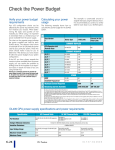
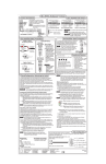
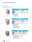
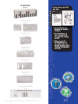
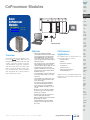
CoProcessor Modules
Company
Information
Systems
Overview
Programmable
Controllers
Basic
CoProcessor
Modules
Field I/O
Software
C-more &
other HMI
F4-CP128-1 <--->
F4-CP128-T <--->
Drives
Operator Interfaces
Soft
Starters
Motors &
Gearbox
Steppers/
Servos
Motor
Controls
Built-in telephone modem
Proximity
Sensors
Features
Overview
The FACTS CoProcessor Module interfaces the DirectLOGIC 405 family of
programmable controllers with bar code
readers, operator interface terminals,
instrumentation equipment, computers,
and other serial devices. The three ports
offer a range of communication interfaces and baud rates. Please consult the
port descriptions to see which module is
best suited for your needs.
• FACTS Extended BASIC and ABM
Commander for Window software makes
program development fast and simple.
Allows ONLINE, full-screen BASIC program editing and the ability to save programs on disk (software on CD included
with each module)
• Non-volatile memory of up to 128K bytes
allows multiple program storage and
execution, DL405 register expansion, and
retentive data storage and retrieval
• 16 MHz or 26 MHz CoProcessor provides
fast program execution independent of
the DL405 CPU scan
• Three buffered ports permit communication from module to three or more external devices
• Programmable from either port for complete serial port utilization without having to switch cables
• A real-time clock/calendar maintains
time/date with battery backup when
power outages occur. Programmable
time-based BASIC interrupts to .005 of a
second
•Directly access up to 254 bytes of DL405
CPU memory per scan. No supporting
ladder logic is required
•Floating point math solves complex formulas to eight significant digits
•Options include a built-in 300/1200/2400
baud telephone modem
•Includes Modbus master/slave BASIC
examples and other application examples on CD
Photo
Sensors
CoProcessor
applications
Limit
Switches
The CoProcessors are designed for use
with intelligent devices such as:
• Barcode readers
• Welders
• Board level controllers
• Serial printers
• Intelligent sensors
• Almost any device with an
RS-232/422/485 port
CoProcessors are also good solutions for
applications requiring large amounts of
complex math.
Encoders
Current
Sensors
Pressure
Sensors
Temperature
Sensors
Pushbuttons/
Lights
Process
Relays/
Timers
Comm.
Terminal
Blocks &
Wiring
Power
Circuit
Protection
Enclosures
Tools
Pneumatics
Appendix
Product
Index
Part #
Index
Volume 13
w w w. a u to m at i o n d i re c t . c o m / d l 405
Programmable Controllers
e6-39
CoProcessor Modules
Specifications
Module Type
Modules per CPU
CoProcessor, intelligent
Eight maximum, any slot in CPU base
Communication
256 character type-ahead input buffer on all ports. Ports are independently
programmed by software. Seven or eight data bits, 1 or 2 stop bits, even,
odd or no parity. XON/XOFF software flow control and RTS/CTS handshake.
F4-CP128-1
128K bytes of battery-backed RAM. 26MHz clock rate. Runs BASIC programs two to three times faster than 16MHz
CoProcessors. Port 1, RS232C/422/485 selectable, maximum baud rate of 115.2K baud. Port 2, RS232C/422/485
selectable, maximum baud rate 57.6K baud. Port 3, RS232C, maximum baud rate of 19.2K baud. Port 3 is available
by using the RTS/CTS pins on Port 1. If you use these lines on Port 1, then Port 3 is not available.
F4-CP128-T
128K bytes of battery-backed RAM, 16 MHz clock rate. Port 1, RS232C/422/485 selectable, maximum baud rate of
57.6K baud. Port 2, RS232C, maximum baud rate 9600 baud. An optional use for port 2 is a built-in full-duplex,
300/1200/2400 baud PSK/FSK, asynchronous telephone modem. The modem is Bell 212A/103 & CCITT V.22/V.21
compatible. Automatic dialer with call progress monitoring detects no dial tone, ring and busy. Automatically answer
calls. Can be used for remote data acquisition and diagnostics. Allows remote reprogramming of both BASIC
CoProcessor and DirectLOGIC 405 CPUs. Exceeds FCC part 68 hazard protection requirements. Port 3, RS232C,
maximum baud rate of 9600 baud. Port 3 is available by using the RTS/CTS pins on Port 1. If you use these lines on
Port 1, then Port 3 is not available.
ABM Commander for Windows (CD-ROM
included with module)
Programming/documentation software for FACTS Engineering BASIC module.
Key features include:
• Runs under Windows 95/98/2000 or Windows NT 3.51 or later.
• Command Mode allows the user to program and debug with a
"Point and Click" or Command Line Interface.
• Uses standard Windows applications for off-line edited (Notepad)
and terminal emulation (Hyperterminal)
• Text Upload and Download BASIC programs
• Binary Upload and Download BASIC programs
• Extensive help file contains full user manual information
• Includes Modbus master and Modbus slave BASIC programs and other
application examples
Field Termination
9 pin D-sub connectors for port 1 and port 2. Port 3 uses electrical connections from port 1. (F4-CP128-T uses an
RJ12 phone jack located under the module)
Power Consumption
F4-CP128-1 — 305mA maximum at 5VDC, (supplied by base power supply)
F4-CP128-T — 350mA maximum at 5VDC, (supplied by base power supply)
Operating Environment
0°C-60°C (32°F-140°F), 5% to 95% humidity (non-condensing)
Manufacturer
FACTS Engineering
Volume 13
e6-40
Programmable Controllers
1 - 80 0 - 633 - 0405
Check the Power Budget
Verify your power budget
requirements
This logo is placed next to I/O modules
that are supported by the ZIPLink connection systems. See the I/O module specifi-
Calculating your power
usage
Your I/O configuration choice can be
affected by the power requirements of the
I/O modules you choose. When determining the types and quantity of I/O
modules you will be using, it is important
to remember there is a limited amount of
power available from the power supply.
cations at the end of this section.
The following example shows how to
calculate the power budget for the DL405
system. The example is constructed around
a single 8-slot base using the devices
shown. It is recommended you construct a
similar table for each base in your system.
The chart on the opposite page indicates
the power supplied and used by each
DL405 device. The adjacent chart shows
an example of how to calculate the power
used by your particular system. These two
charts should make it easy for you to
determine if the devices you have chosen
fit within the power budget of your system
configuration.
A
Base Number
0
B
Use ZIPLinks to reduce
power requirements
If your application requires a lot of relay
outputs, consider using the ZipLink AC or
DC relay output modules. These modules
can switch high current (10A) loads
without putting a load on your base power
budget. Refer to page 6-57 for more information.
5 VDC (mA)
External 24 VDC
Power (mA)
CURRENT SUPPLIED
CPU/Expansion Unit
/Remote Slave
D4-440 CPU
C
3700
400
CURRENT REQUIRED
SLOT 0
SLOT 1
SLOT 2
SLOT 3
SLOT 4
SLOT 5
SLOT 6
SLOT 7
D4-16ND2
+150
+0
D4-16ND2
+150
+0
F4-04DA
+120
+100
D4-08ND3S
+100
+0
D4-08ND3S
+100
+0
D4-16TD2
+100
+0
D4-16TD2
+100
+0
D4-16TR
+1000
+0
BASE
Handheld Programmer
D4-08B
+80
+0
D4-HPP
+320
+0
E Maximum Current Required
2820
100
F Remaining Current Available
3700-2820=880
400-100=300
If the I/O you have chosen exceeds the
maximum power available from the power
supply, you can resolve the problem by
shifting some of the modules to an expansion base or remote I/O base (if you are
using remote I/O).
Warning: It is extremely important to calculate the
power budget correctly. If you exceed the power budget, the system may operate in an unpredictable manner which may result in a risk of personal injury or
equipment damage.
Device Type
D
OTHER
1. Using a chart similar to the 3one above, fill in column 2.
2. Using the tables on the opposite page, enter the current supplied and used by each device (columns 3 and 4). Pay special attention to the current supplied by the CPU, Expansion Unit, and Remote Slave since they differ. Devices which fall into the "Other" category (Row D) are devices such
as the Base and the Handheld programmer, which also have power requirements, but do not plug directly into the base.
3. Add the current used by the system devices (columns 3 and 4) starting with Slot 0 and put the total in the row labeled "maximum current
required" (Row E).
4. Subtract the row labeled "Maximum current required" (Row E), from the row labeled "Current Supplied" (Row B). Place the difference in the row
labeled "Remaining Current Available" (Row F).
5. If "Maximum Current Required" is greater than "Current Supplied" in either column 3 or 4, the power budget will be exceeded. It will be unsafe to
use this configuration and you will need to restructure your I/O configuration. Note the auxiliary 24 VDC power supply does not need to supply all
the external power. If you need more than the 400mA supplied, you can add an external 24VDC power supply. This will help keep you within your
power budget for external power.
DL405 CPU power supply specifications and power requirements
Specification
Part Numbers
AC Powered Units
D4-450, D4-440, D4-430,
D4-EX (expansion base unit),
D4-RS (remote slave unit)
Voltage Withstand (dielectric)
Insulation Resistance
24 VDC Powered Units
D4-450DC-1, D4-440DC-1,
D4-EXDC (expansion base unit),
D4-RSDC (remote slave unit)
125 VDC Powered Units
D4-450DC-2
D4-440DC-2
1 minute @ 1,500 VAC between primary, secondary, field ground, and run relay
> 10M at 500VDC
Input Voltage Range
85-132 VAC (110 range) 170-264 VAC (220
range
20-28 VDC (24 VDC)
with less than 10% ripple
90-146 VDC (125 VDC)
with less than 10% ripple
Maximum Inrush Current
Maximum Power
20 A
20 A
20 A
50 VA
38 W
30 W
Volume 13
e6-24
Programmable Controllers
1 - 80 0 - 633 - 0405
Power Requirements
Company
Information
Systems
Overview
Programmable
Controllers
Power Supplied
CPUs/Remote Units/
Expansion Units
5 VDC Current
Supplied in mA
24V Aux Power
Supplied in mA
CPUs/Remote
Units/Expansion Units
5V Current Supplied
in mA
24VAux. Power
Supplied in mA
D4-430 CPU
D4-440 CPU
D4-440DC-1 CPU
D4-440DC-2 CPU
D4-450 CPU
D4-450DC-1 CPU
D4-450DC-2 CPU
3700
3700
3700
3700
3100
3100
3100
400
400
NONE
NONE
400
NONE
NONE
D4-EX
D4-EXDC
D4-EXDC-2
D4-RS
D4-RSDC
H4-EBC
H4-EBC-F
4000
4000
3700
3700
3700
3470
3300
400
NONE
NONE
400
NONE
400
400
Field I/O
Software
C-more &
other HMI
Drives
Power Consumed
Power-consuming
Device
I/O Bases
5V Current
Consumed
D4-04B-1
D4-06B-1
D4-08B-1
80
80
80
External 24VD
Current Required
NONE
NONE
NONE
DC Input Modules
D4-08ND3S
D4-16ND2
D4-16ND2F
D4-32ND3-1
D4-32ND3-2
D4-64ND2
100
150
150
150
150
300 max.
NONE
NONE
NONE
NONE
NONE
NONE
Power-consuming
5V Current
Device
Consumed
Analog Modules (continued)
External 24VDC
Current Required
F4-16AD-1
F4-16AD-2
F4-04DA-1
F4-04DA-2
F4-04DAS-1
F4-04DAS-2
F4-08DA-1
F4-08DA-2
F4-16DA-1
F4-16DA-2
F4-08RTD
F4-08THM-n
F4-08THM
100
100
75+20per circuit
90
60 per circuit
60 per circuit
100+20 per circuit
150
100+20 per circuit
25 max.
NONE
50
60
75
75
70
90
60
60
90
80
90
80
80
120
110
Motors &
Gearbox
100
150
Photo
Sensors
Limit
Switches
NONE
NONE
H4-ERM
H4-ERM-F
D4-RM
320
450
300
NONE
NONE
NONE
Pressure
Sensors
Temperature
Sensors
150
90
D4-08TD1
F4-08TD1S
D4-16TD1
D4-16TD2
D4-32TD1
D4-32TD1-1
D4-32TD2
150
295
200
400
250
250
350
D4-64TD1
800
NONE
NONE
35
NONE
125
NONE
140
140 (15V)
120 (4A max
including loads)
NONE
Communications and Networking
H4-ECOM100
H4-ECOM
H4-ECOM-F
D4-DCM
F4-MAS-MB
FA-UNICON
300
530
670
500
235
NONE
Pushbuttons/
Lights
NONE
NONE
NONE
NONE
NONE
65
Process
Relays/
Timers
Comm.
CoProcessors
F4-CP128-1
Terminal
Blocks &
Wiring
305
NONE
Power
AC Output Modules
250
450
NONE
NONE
Relay Output Modules
D4-08TR
F4-08TRS-1
F4-08TRS
D4-16TR
Proximity
Sensors
Current
Sensors
DC Output Modules
D4-08TA
D4-16TA
Motor
Controls
Encoders
AC/DC Input Modules
D4-16NE3
F4-08NE3S
Steppers/
Servos
Remote I/O
AC Input Modules
D4-08NA
D4-16NA
Soft
Starters
550
575
575
1000
NONE
NONE
NONE
NONE
Specialty Modules
H4-CTRIO
D4-INT
D4-HSC
F4-16PID
F4-8MPI
D4-16SIM
F4-4LTC
Circuit
Protection
400
100
300
160
225
150
280
NONE
NONE
NONE
NONE
170
NONE
75
Enclosures
Tools
Pneumatics
Appendix
Analog Modules
Programming
320
NONE
Product
Index
DV-1000
150
NONE
Part #
Index
C-more Micro-Graphic
210
NONE
D4-HPP-1 (Handheld Prog.)
F4-04AD
F4-04ADS
F4-08AD
85
270
75
100
120
90
Operator Interface
Volume 13
w w w. a u to m at i o n d i re c t . c o m / d l 405
Programmable Controllers
e6-25