1
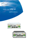
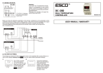
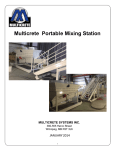
…no limits
of application!
EN
History…
IMET was founded in 1988 and is without doubt one of the pioneering
companies in the development and manufacture of radio remote controls.
The first prototypes of radio remote control systems appeared on the market
by the end of the 1980’s spreading initially in the fields of construction cranes
and concrete handling.
Within the next few years and as a consequence of the increasing importance
of productivity and safety in the industrial and construction fields, the demand
of radio remote control systems increased massively and IMET, thanks to
the dynamism and high level of technical competence of its staff along with
its constant bent towards a technological innovation process, has gained a
prominent position on all national and international markets.
Today…
…IMET can boast a very wide and articulate range of products, able to suit
the majority of different requirements inside the industry and construction
field and much more. In addition to the standard models, which have been
designed for the most traditional application fields, such as construction
cranes, bridge cranes and many others, IMET places at the disposal of its
customers a staff of technicians, specialised in the design and creation of
customised models of radio remote controls, according to the customer’s
specific requirements...with no limits of application.
RESEARCH, DEVELOPMENT
AND SAFETY
IMET radio remote controls have always
distinguished themselves with their
extreme reliability attained through the use
of high quality materials, combined with
intense research and extensive product
testing. This has resulted in the achievement
of safety standards of category 2 and 3 for
all movement commands and category 4 for
the STOP circuit (UNI EN 954-1).
PRODUCTION
IMET radio remote controls are totally designed and assembled in-house and also
subjected to a series of intermediate quality control and final testing, in order to
assure quality and reliability. It is this level of hands on control which has enabled
IMET to gain the quality mark UNI EN ISO9001: 2000.
Venice
…no limits of application!
The extremely large range of transmitters and receivers
allows IMET to solve many applications within the
construction and industrial fields without deviating from
the standard range of products. The pushbutton WAVE
family has been specifically designed for the optimal
control of hoists, overhead travelling cranes, tower cranes
and, generally speaking, on/off controlled machines; the
waist belt transmitter families are addressed to the vast
world of joystick controllable machines whether they are
proportional or on/off types. The control panel of the ZEUS
models can accomodate up to 2 double axis joysticks (B2) or
6 single axis joysticks (M6) in addition to several commands
by means of push buttons, selector or rotary switches and
potentiometers; The THOR waist belt transmitter family
extends furthermore the range of possibilities. The large
space available on its control panel allows for up to 4 double
axis joysticks (B4) or 8 single axis joysticks (M8) in addition to
a huge number of push buttons, selector or rotary switches
and potentiometer commands; The fixed transmitter
M8, designed for Din rail mounting, can be applied in
all situations where on/off and proportional commands
generated by sensors or RS 232/485 ports, are required to
be wirelessly transmitted to a control station. The receiver
range is based on 4 models L, H, M and K providing a range
of product capable of satisfying most requirements in terms
of number of on/off and proportional outputs required. All
M550 series families can be enhanced by the addition of a
data feedback option, allowing machine status information
to be displayed, on LCD or LED screens.
IMET products are designed in respect of the highest
safety standards: CAT4 (UNI EN 954-1) for the STOP circuit,
and CAT3 and 2 for the movement commands. The concepts
of “redundancy”,“cross –check”,“self-checking” and “periodic
monitoring” are present in every single product part where
safety is important. All this brings IMET to a leading position
within the industry in active and passive safety care.
All important and critical parts of a radio remote control
system are fully designed and manufactured in-house at
IMET. This includes complex components such as the optical
joysticks, the simplex and half-duplex radio modules, the SMD
boards and even the PWM electro-hydraulic actuators “Hydra
system”. The mastery of the radio know-how together with the
use of cutting edge technologies enables IMET to control and
manage every single aspect of the manufacturing process. Two
key words have always been a guide for IMET growth:
Quality and flexibility, with no compromise.
The great autonomy granted by the Ni-MH batteries allows the
continuity of works and operations.
Transmitters and receivers with standard protection rating of
IP65 are manufactured in composite material (nylon charged
with fiber glass) with high shock-resistance, thermal and
mechanical stability, environmental and chemical exposure
resistance. All of these features combine to provide a product
capable of giving many years of continuous operation in harsh
working conditions.
The electronic boards are coated with a special protective
synthetic film for improving the resistance to humidity, chemical
agents and vibrations.
All IMET portable transmitters are equipped with a supply
magnetic key that limits the use of the radio control only to
authorized personal.
Data feedback: the “half-duplex” radio technology combined
with an “input interface card”, where both on/off and
proportional inputs are available, fitted in the receiver, enables
information to be sent back to the transmitter from the machine
sensor’s. This feature is available with the pushbutton WAVE, the
waist belt ZEUS/THOR and the fix-Din transmitters, in all cases
data is displayed on an LCD or LED display. In addition, the fixDin mounting transmitter can receive on/off commands from
the data feedback channel and activate them with 16 relays.
TRASMITT
M550 WAVE S
The pushbutton radio type M550 WAVE S
range is available with 4, 6 or 8 double-step
pushbuttons for the movement commands.
In addition, and always present is a Start/
Klaxon button and a STOP mushroom-head
button. The radio remote also has space
for one optional command which can be a
multi-position rotary switch, a single-step
button or an analogue potentiometer.
IMET have paid special attention to the
ergonomic design of the WAVE transmitter
bearing in mind the practical aspects of
compact overall size, large pushbuttons
suitable for operations with gloves, easy
access and protected STOP button. This
make the WAVE S an ideal tool for the
control of hoists, overhead cranes and
small tower cranes. The possibility of
customisation extends the possible uses
of this type of transmitter to a large variety
of machines equipped with on/off control
boxes whether AC or DC powered.
6
Dimensions
75 x 43 x 180 mm
Weight
375 g
TING UNIT
M550 WAVE L
The pushbutton radio M550 WAVE L range
is available with either 10 or 12 doublestep pushbuttons for the movement
commands in addition to the standard
Start/Klaxon button and STOP mushroomhead button. The model M550D WAVE
L10 can be equipped with a 8+8 digit LCD
screen for the displaying of machine status
information (using data feedback option).
As with the WAVE S, the transmitter has
space for an optional command which can
be a multi-position rotary switch, a singlestep button or an analogue potentiometer.
This makes the WAVE L a natural choice for
the control of overhead cranes equipped
with additional functions such as auxiliary
hoist, grabs, magnets, etc. and medium
size tower cranes. The possibility of
customisation again extends the possible
uses of this type of transmitter to a large
variety of machines equipped with on/off
control boxes whether AC or DC powered.
Dimensions
75 x 43 x 245 mm
Weight
445 g
7
TRASMITT
M550 ZEUS B2
The ZEUS B2 transmitter combines the advanced ergonomic design and
functional features required in standard application fields such as tower
cranes, factory cranes, small concrete pumps, high pressure and vacuum
pump vehicles and any other kind of machine for witch double-axis
joysticks represent the ideal type of movement command.
The ZEUS B2 console has a compact size but nevertheless it reserves
ample space for on/off and proportional commands making it an easily
customisable transmitter for special applications.
8
Dimensions
212 x 133 x 147 mm
212 x 169 x 147 mm
Weight
1090 g
TING UNIT
M550 ZEUS M6
The ZEUS M6 transmitter utilises the same transmitter body as the B2,
combined with specially designed proportional joysticks for applications
such as hydraulic proportional cranes, telescopic handlers, crawler
vehicles and any other kind of machine for witch single-axis joysticks
represent the ideal type of movement command. The ZEUS M6 console
has a compact size but again, reserves plenty of space for additional on/off
and proportional commands making it an easily customisable transmitter
for special applications
9
Dimensions
296 X 152 X 147 mm
296 X 190 X 147 mm
Weight
1450 g
TRASMITT
M550 ZEUS NJ
The transmitter ZEUS NJ has been developed for use with high complexity
machines where proportional potentiometers, push-buttons and selector
switches represent the ideal types of movement commands. The spacious
console has room for a large number of commands making ZEUS NJ
flexible and customizable for complex AC and DC powered applications.
10
Dimensions
212 x 133 x 147 mm
212 x 169 x 147 mm
Weight
1090 g
TING UNIT
M550 THOR B3
The THOR B3 transmitter has been designed for use with a vast range of
complex and high integrity machines, such as, 4-5 booms concrete pumps,
full accessory equipped factory cranes, 6 functions hydraulic cranes,
special tower cranes, drilling and tunnelling machines. In addition to the 3
double axis joysticks, the extra wide THOR console has capacity for several
on/off and proportional commands making it an easily customisable
transmitter for special applications whether AC or DC powered.
11
Dimensions
296 X 152 X 147 mm
296 X 190 X 147 mm
Weight
1450 g
TRASMITT
M550 THOR B4
The THOR B4 transmitter is similar to the B3, but with the addition of a
fourth, double axis joystick. This makes it an ideal system for High Integrity
factory cranes, 7-8 functions hydraulic cranes, crawler lifting machines
and other special machines. In addition to the 4 double axis joysticks, the
THOR console has space available for several on/off and proportional
commands making it an easily customisable transmitter for special
applications whether AC or DC powered.
1
Dimensions
296 X 152 X 147 mm
296 X 190 X 147 mm
Weight
1550 g
TING UNIT
M550 THOR M8
The THOR M8 transmitter is equipped with up to 8 single-axis joysticks
and is specifically designed for machines moved by proportional electrohydraulic valve banks such as, 7-8 functions hydraulic cranes, crawler
lifting machines and other special machines. In addition to the 8 single
axis joysticks, the very wide THOR console has room for several on/off and
proportional commands making it an easy to customise the system for
complex DC powered applications.
13
Dimensions
296 X 152 X 147 mm
296 X 190 X 147 mm
Weight
1450 g
TRASMITT
M550 THOR NJ
The THOR NJ transmitter is intended for use on machines with high
complexity where proportional potentiometers, push-buttons and
selector switches represent the ideal types of movement commands.
The very wide console has room for an incredible number of commands
making THOR NJ very flexible and customisable for complex AC and DC
powered applications.
1
Dimensions
296 X 152 X 147 mm
296 X 190 X 147 mm
Weight
1400 g
TING UNIT
M550 M8
The M8 transmitter is designed for mounting on a DIN rail, and is the ideal
solution for applications requiring wireless transmission for on/off and/or
proportional commands coming from sensors or RS485 port.
The DIN rail mounted transmitter should be placed inside a control box
for clean and trouble free installation, and is supplied complete with an
external antenna for the radio communication. In addition to the 21 on/off
+ 4 proportional commands, Start, Stop and Frequency Change input are
available as for traditional radio control commands.
The double transmission version can manage the feedback information
displaying it on a LCD screen or activating some transmitter built in relays.
15
Dimensions
180 x 120 x 73 mm
Weight
910 g
TRASMITT
…NO LIMITS…
16
TING UNIT
BATTERY CHARGER
IMET battery chargers are ready for 11÷32 Vdc (with cigarette lighter plug)
or 230 Vac power supply (Shuko plug).
The housings are IP30 and working temperature can range between 0 and
35 °C. Thanks to the “smart” design, the charging process considers the
intrinsic Ni-MH cell features and the initial charge status.
It results in optimal charging cycles in the lowest possible time (maximum
3 hours for the complete charge).
17
Dimensions CB3600 Zeus / Thor
75x49x156 mm
Dimensions CB5000 Wave
75x49x142 mm
Weight
251 g
Weight
250 g
RECEIVING
RECEIVING UNIT
IMET transmitting units can be matched to 4 models of receivers. The
L and H types have IP65 housings, for outdoor installation, while the M
type features a housing ready for Din rail mounting inside the machine
electric control box. The M550 K receiver, which also features a protection
level of IP65, is dedicated to machines controlled by CAN BUS network.
The available IP65 receiver output connections are: cable clamp, multipole connector fixed on the box, external wiring and multipole plug
for connection to the machine. The M type receiver is equipped with a
terminal block output connector. All IMET receivers have a Category 4
STOP circuit, and the presence of the Safety-Stop relay adds one level to
the category of the movement commands reaching CAT2 and 3 (not valid
for bus commands). LED Lights, visible from outside the receiver indicate
the system status. The special composite material used for the housings
provides a high level of shock resistance and thermo-mechanical stability.
18
The M550 L is the most common receiver for standard applications, its
compact size and high versatility make it ideal for situations where space
constraints are an issue. It is the natural receiver type for on/off application
in VAC and VDC and for standard application requiring proportional
outputs in VDC such as hydraulic cranes. The LAC receiver accepts a wide
range of supply voltages (24÷230VAC) and it is equipped with 20 relays for
the movement commands in addition to the Start, Stop and Safety Stop
outputs. The LDC receiver can be supplied with 12÷28VDC. It is available
in two versions: with 16 relays for the movement commands or with 20
solid state on/off + 8 proportional outputs for the movement commands in
addition to the Start, Stop, Safety Stop and Timed Stop outputs.
The M550 H receiver is ready for the most complex configurations. Its
modular structure allows it to be equipped it with up to 48 relays or 38
relays + 8 proportional outputs in addition to the Start, Stop, Safety Stop
and Timed Stop outputs. The data feedback option is guaranteed by mean
of half-duplex radio modules.
This receiver is the common partner for transmitting units having a large
number and variety of commands. The HAC receiver can be powered with
24 to 230VAC while the HDC accepts 12 to 28 VDC.
G UNIT
The M550 M receiver has been developed for Din rail mounting inside
electrical control panels. The outputs are available on practical extractable
terminal blocks. This kind of receiver has 21 relays + 4 proportional outputs.
It can be equipped with half-duplex radio modules for the data feedback
option. M550 M is supplied with an external antenna plugged on BNC
connector. The power supply can range between 12 and 28 VAC/DC.
The M550 K receiver is equipped with a field bus output, CAN type, for
the movement commands. The CAN bus output is directly coupled to the
machine bus network and the communication is established trough a
specific protocol. Traditional relay outputs are present for Start, Stop, SafetyStop and Timed-Stop functions.
The M550 K receiver can be DC powered (12÷28VDC).
19
M
Dimensions
180 x 120 x 73 mm
L/K
Dimensions
145 x 65 x 225 mm
H
Dimensions
205 x 280 x 130 mm
Weight
910 g
Weight
1700 g
Weight
3500 g
TECHNICAL IN
General data
Working frequency
Reference norms
Channel spacing
Number of P.L.L. programmable radio channels
Range
Modulation
Emission power of the R.F. system
RF receiver type
Receiver sensibility
Emission class
Hamming distance
Error non-detection probability
Delay time on receiver start
Available pairing addresses
Delay time on the start command
Response time of commands
Response time of active emergency
Response time of passive emergency
Safety category of STOP command
Safety category of movement commands
I.S.M Band 434.050 ÷ 434.775 MHz
ETSI EN 300 220-3 V 1.1.1
25 KHz Simplex, (25 KHz Half Duplex)*
30
100 m
GMSK
10 mW ERP (Antenna Interna)
Supertherodine IF 83.16 MHz - 455 KHz*
0,22µV per 12 dB Sinad
25K0F1D
9
< 7.34 x 10⁻¹²
<3s
65536
< 750 ms
< 110 ms, < 120 ms*
< 150 ms, < 220 ms
< 800 ms
3 (UNI EN 954-1) M / 4 (UNI EN 954-1) W-Z-T
1÷2 (UNI EN 954-1) W-M / 2÷3 (UNI EN 954-1) Z-T
Safety category of
datafeedback commands
20
1 (UNI EN 954-1)
Datafeedback ready
Operation and storage temperature
Trasmitting Unit
Max. quantity of ON/OFF direct commands
Max. quantity of ON/OFF undirect commands
Max. quantity on analogue commands
Service and Safety commands
Housing protection degree
Housing material
Supply tension
Current demand
Power demand
Battery
Autonomy at 20 °C with charged battery
continuos operation
Advice time “battery down”
YES
-20 ÷ +70°C, (-4 ÷ 158°F)
M8
32
48
8
Wave S-L
Zeus-Thor
16 S - 24 L - 20 L*
32
48
48
1
8
4 (Start, Klaxon, Blinker, Stop)
/
IP65
IP65
ABS
charged Nylon charged Nylon
12 min - 28 max
Vac/Vdc
2,4 Vdc
3,6 Vdc
240mA - 260mA* 100mA - 120mA* 160mA - 180mA*
1,4 W - 1,5 W*
0,3 W
0,58 W - 0,65 W*
/
NiMh 2,4V-1,5A/H NiMh 3,6V-1,7A/H
/
/
15 hours ,
12 hours *
15 min
12 hours,
10 hours*
15 min
LCD Display (optional)
2 lines 16 ch.
/
2 lines 8 ch.
/
2 lines 16 ch.
4 lines 20 ch.
Visualisation speed for the ch. on the display*
Max. quantity of command relays (NO)
Max. carrying capacity of command relays
Input ports (optional)**
100 char/s
16*
6A
Seriale RS485
100 char/s
/
/
/
100 char/s
/
/
/
NFORMATION
Receiving Unit
Service commands
Safety commands
Max. quantity of ON/OFF command (NO)
Max. quantity of analogue command
PWM analogue output
M550 H
M550 L / K
M550 M
Start, T-Stop,
Horn, Blink
Start, (Horn,
T-Stop)***
Start, Horn,
Blink
Safety-stop, Stop Safety-stop, Stop Safety-stop, Stop
48
20
21
8
8
4
0 ÷ 1,4 A max
0 ÷ 1,4 A max
/
0 ÷ 20 mA
4 ÷ 20 mA
0 ÷ 20 mA
4 ÷ 20 mA
0 ÷ 20 mA
4 ÷ 20 mA
Analogue output in tension
min 25% Vcc
med 50% Vcc
max 75% Vcc
min 25% Vcc
med 50% Vcc
max 75% Vcc
min 25% Vcc
med 50% Vcc
max 75% Vcc
Analogue output in tension
Housing protection degree
Housing material
Datafeedback ready
0 ÷ (Vcc-3) reg.
IP65
charged Nylon
YES
0 ÷ (Vcc-3) reg.
IP65
charged Nylon
YES
0 ÷ (Vcc-3) reg.
/
ABS
YES
Serial,
parallel
CAN,
Serial, parallel
Serial,
parallel
Analogue output with loop of current
Input ports*
Max quantity of digital inputs*
Max. quantity of analogue inputs*
Supply tension Vac
Supply tension Vdc
Power demand
8
8
11
4
4
4
24, 48, 55, 110, 230 24, 48÷55, 110, 230 12 min - 28 max
12 min - 28 max 12 min - 28 max 12 min - 28 max
20 W max
15 W max
15 W max
21
Battery charger
CB5000 Wave
CB3600 Zeus / Thor
Supply tension
12 min - 32 max Vdc
(optional 230 Vac)
12 min - 32 max Vdc
(optional 230 Vac)
Power demand
250mA DC, 35mA AC,
(while charging)
250mA DC, 35mA AC,
(while charging)
550mA
3 hours
PVD
IP30
600mA
3 hours
PVD
IP30
+5 ÷ + 45°C
(+41 ÷ +113°F)
+5 ÷ + 45°C
(+41 ÷ +113°F)
-20 ÷ +70°C
(-4 ÷ +158°F)
-20 ÷ +70°C
(-4 ÷ +158°F)
75x49x142 mm
250g
490g
75x49x156 mm
251g
491g
Charging current
Max. charging time
Charge type
Housing protection degree
Storage temperature with loaded battery
Storage temperature off and without battery
Dimensions (L.P.H.)
Weight
Weight with 230Vac transformer (optional)
M= Trasmitting unit M8
W= Trasmitting unit Wave
Z= Trasmitting unit Zeus
T= Trasmitting unit Thor
* Datafeedback version
** Only for data acquisition
*** DC
HYDRAULIC
HYDRAULIC ACTUATOR
The “PWM Hydra system” combining electro hydraulic-actuators, with
either ZEUS and THOR radio remote controls, allows the conversion of
hydraulic manual cranes into radio controlled ones.
The actuator hydraulic circuit is totally independent from the crane
hydraulics, hence avoiding oil-sharing problems that can arise due to the
presence of dirt in the crane oil compromising the regular working of the
actuator pistons.
The power pack works only “on demand”, when movements are operated
from the transmitter, granting low stress conditions and reducing all
energy wastes.
The calibration of every single actuator can be performed via radio
directly from the transmitter. The Hydra system kit is comprehensive,
and consists of: block of actuators, power pack, wiring between receiver/
actuators/power pack, rod clamps, hydraulic pipes.
22
C ACTUATOR
ACTUACTOR
COMMAND
ACTUACTOR
CONNECTOR
COMMAND
ACTUACTOR
CONNECTOR
DISTRIBUTOR
ANCHORING
CLAMP
CRANE ROD
1 2
T
UNIT PACK
SUPPLY
CONNECTOR
1
MOTOR
ELECTRONIC
CONTROL
P
PWM Hydra system
optional
OIL FILTER
BY-PASS
ELECTRO-VALVE
DRAIN PIPE
PUMP
Hydraulic Actuator
Pilot system
Coil resistance by 20°C (68°F)
Absorption by 27 Vdc
Absorption by 13,5 Vdc
Operating room temperature
Max. stroke
Max. stroke optional
Thrust and traction force by 12 bar
Optimum operation pressure
Max. available operation pressure
Connectors of hydraulic circuit
Dimensions (L. P. H.)
Weight (single module)
Standard interaxe
Standard functions
PWM a 80Hz
5,5 Ohm
170 ÷ 620 mA
300 ÷ 1250 mA
-20°C ÷ +70°C (-4°F ÷ 158°F)
26 mm (±13mm from the centre)
40 mm (±20mm from the centre)
600N
15 ÷ 20 bar
30 bar
1/4“ Gas
210 x 38 x 138 mm
1500 g
38, 42, 44, 46, 48, 50 mm
4÷8
Electrohydraulic Power Pack
Absorption by 27 Vdc
Absorption by 13,5 Vdc
Supply tension
Working pressure
Working room temperature
Tank capacity
Connectors of the hydraulic circuit
Dimensions (L. P. H.)
Dry weight
4,5A
9A
12 o 24 Vdc +20% -10%
18 bar 27 Vdc - 16 bar 13,5 Vdc
-20°C ÷ +70°C (-4°F ÷ 158°F)
0,5 litres
1/4“ Gas
305 x 120 x 160 mm
4850 g
3
HYD
TRANSMITTERS FOR
HYDRA SYSTEM
ZEUS M and THOR M transmitters,
equipped with single axis joysticks,
are particularly suitable for
controlling Hydra system.
The biaxial joystick versions can
also be used.
RECEIVERS FOR
HYDRA SYSTEM
LDC and HDC receivers are suitable
as they feature VDC powering,
PWM proportional outputs and
IP65 protection for outdoor use.
COMPREHENSIVE WIRING
A user friendly wiring kit comes ready with each
system in order to facilitate all the electrical
connections between receiver/actuators/power pack.
A practical key-switch allows the operator to select
the operation mode (RC, Off, manual).
POWER PACK
An electro-hydraulic pump that works only
“on demand” supplies the oil to the actuators
rendering the Hydra system totally independent
from the machine oil circuit.
DRA SYSTEM KIT
ACTUATOR BLOCK
The modular structure of a block of actuators allows customisation for specific
applications. The actuator piston stroke is +/- 13 mm making it suitable for use with
the vast majority of the hydraulic distributors on the market. For those special cases
demanding a larger rod stroke up to 20 mm, a stroke-extension kit is available.
Thanks to dedicated mechanical adapters, it is possible to interface the actuators
directly with one side of the manual valve bank (available for Walvoil SD6, SD8,
Galtech and Parker). This configuration requires removal of the rods.
ROD CLAMPS
The actuators transmit the
mechanical movement to
the rods through clamp on
adaptors. No welding required.
HYDRAULIC TUBES AND PIPES
Tubes and pipes are supplied for all
hydraulic connections between the
actuator block and the power pack.
OPTIONALS AND ACCESSORIES
The serial cable option (15 m) is
available for a wire-connection between
transmitter and receiver. The radio
modules are thus not active and the
transmitter is powered directly from the
serial cable. We can supply a by-pass valve
when required.
25
OTHER PRODUCTS
PLE: AERIAL PLATFORM CONTROL BOARD
26
The IMET PLE electronic board performs the diagnostic checks, and stores data
relating to the working status for lifting machines such as cranes with basket
and aerial platforms.
The PLE system computes the information coming from micro-switches and
sensors placed on the machine for different functions, e.g. stabilizing, slewing
limit switch, basket presence on the crane, radio control presence in the basket,
hydraulic circuit oil pressure and the “double beam” check trough its microswitch. All the commands executed by the IMET radio remote control are
provided as inputs to the PLE allowing it to supervise in real time the complete
system thus granting safe working conditions to the operator. It is possible
furthermore to create a database of certain parameters which can then be
analysed at a later date.
The special PLE housings are highly resistant, stable and waterproof.
The device can work in an extremely large range of temperature.
The housing is externally equipped with luminous leds to monitor continuously
the stabilization and PLE working status, a Stop-button, a key switch selector
(local/off/R.C.) and a Start button for the activation in manual (“local”) mode.
PLE COMPOSITION SET
The complete set consists of: PLE board and cabling with standard connectors.
RADIO TRANSPONDER
The IMET transponder has been designed in order to solve problems due to the
presence of radio transmission critical obstacles between the operator and the
receiver placed on the machine. It can be suitable also in cases of not common
range needs.
In normal conditions the range is around 100m but the presence of concrete
or metallic areas and of hills, can cause a strong radio link reduction till its
interruption. Commonly, operators belonging to the fields of water jet/vacuum
cleaning, forestry and tower cranes can be involved in such situations.
The compact sizes together with the IP65 housing and the battery powering,
allow an easy and fast positioning of the device in the optimal working point.
The TPDR can complete all M550S IMET radios thanks to a simple tuning
procedure. After the log off of the transponder, the original radio remote control
can work again in its normal configuration.
S AND OPTIONS…
COMPOSITION SET
The complete set consists of: one M550TPDR, a battery charger, two Ni-MH
rechargeable batteries, a user manual, CE declaration.
DYNAMIC SPEED CONTROL
DSC (Dynamic Speed Control) is a new function improving proportional
movement precision of hydraulic cranes and concrete pumps. The machine
operator can adjust in real time the levels of the “slow speed” mode activating
DSC+/- tuning the machine response to the specific working session
conditions.
MULTI RECEIVER AND TRANSMITTER
CONFIGURATIONS
IMET can suit to special configuration requests demanding the simultaneous
use of several transmitters and/or receivers.
a) Tandem, Catch/Release, Master/Slave operation modes are available in
order to satisfy the most complex needs of factory cranes.
b) Receiver selection: This option allows the transmitter to select up to 8
receivers or 8 combinations of some receivers.
DATA FEEDBACK
The displaying in the transmitter of data collected from sensors installed on
board of the machine, allows the operator to be informed about the system
status improving thus the general safety condition.
7
CAT01-03.08 EN
IMET Srl reserves the right to make eventual changes to the product without notice.
IMET s.r.l. - Via Fornace, 8
33077 Sacile (PN) Italy
Tel. +39 0434 7878
Fax +39 0434 737848
www.imet.eu - [email protected]