1
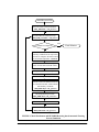
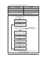
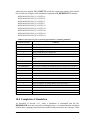
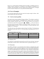
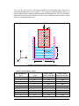
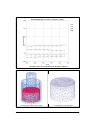
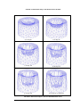
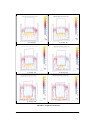
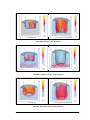
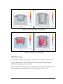
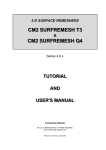
Automation Implementation of Mesh
Enrichment Based Forming Process
Simulation
J. Wan, M. S. Shephard and O. Klaas
SCOREC, RPI
12/05/2001
1.0 Introduction
It is critically important to develop a procedure by which the simulation and mesh enrichments can be automatically run without user intervention till the simulation is completed.
This document describes the implementation of a scripting-based procedure that can
accomplish the task.
DEFORM can be run in two modes, the GUI mode and the text-only mode. The text -only
mode of DEFORM will be run so that the scripting-based automation procedure can be
implemented. The text-only mode of DEFORM is based on scripts. Each functionality,
like preprocessing, rezoning, simulation running, etc. is called from a specific script. The
scripts are glued together by a main control program that calls the scripts sequentially.
State information between the modules is transferred via temporary files.
The data flow of the mesh enrichments based forming process simulation is illustrated
below. Figure 1 shows a version based on DEFORM’s rezoning function. When we add
our procedure then rezoning happens with the mesh modification and the data flow is
shown in Figure 2. In the context we describe the different scripts along with the required
keystrokes used to run the DEFORM functionalities and the necessary modification on the
required user defined FEM routines in the DEFORM’s rezoning based version. We will
also describe the temporary files that need to be created.
Since a newly-provided user defined subroutine, USRMSH, needs to be called during the
simulation to pass the object meshes, boundary conditions and solution fields from the
FEM engine at the starting point of a step in which the mesh of the workpiece becomes
invalid, the automation program can be run with DEFORM v3.30 or above.
2.0 Parameters for System Configuration
To deliver a proper control of the automation process, the following parameters need to be
predefined in an ASCII file, GE_SIM_CTL.TXT, which is located in the current directory where the main program is started, as shown in Table 1.
Automation Implementation of Mesh Enrichment Based Forming Process SimulationDecember 7, 2001
1
Initial Keyword File
Generate initial simulation database
(DEF_PRE.EXE < GE_pre1.scr)
Run DEFORM till simulation stops
(DEF_SIM_local.EXE < GE_sim.scr)
YES
Is simulation completed?
Final Solution
NO
Extract mesh data, solution fields and
boundary conditiona at last step before
the mesh of workpiece becomes invalid
via user defined subroutine, USRMSH
Construct a mesh model of workpiece
based on mesh data and nodal contact
Improve the mesh of workpiece
Assemble the updated keyword file
Generate a reference database based on
the extracted mesh data, solution fields
and boundary conditions
(DEF_PRE.EXE < GE_pre2.scr)
Rezone based on the reference database
and the updated keyword file
(DEF_REM.EXE < GE_rezon.scr)
Place the updated contact conditions
Generate continuing simulation database
(DEF_PRE.EXE < GE_pre3.scr)
FIGURE 1. Mesh Enrichment and DEFORM Rezoning based Automatic Forming
Process Simulation
Automation Implementation of Mesh Enrichment Based Forming Process SimulationDecember 7, 2001
2
TABLE 1. Control parameters defined in GE_SIM_CTL.TXT
Keywords
Example Contents
Comments
WORKDIR
/users/GE/temp
Working directory
INITKEY
/users/GE/keys/part1.KEY
Initial keyword file name
DATABASE
/users/GE/dbs/part1.DB
Database file to be created or appended on
DEFORMDIR
/usr/local/deform3D/3.3
DEFORM installation directory
DEFORMLOCAL
/users/GE/deform_local
The local directory containing the modified FEM
engine,DEF_SIM_local.EXE.
Initial Keyword File
Generate initial simulation database
(DEF_PRE.EXE < GE_pre1.scr)
Run DEFORM till simulation stops
(DEF_SIM_local.EXE < GE_sim.scr)
YES
Is simulation completed?
Final Solution
NO
Extract mesh data, solution fields and
boundary conditions at last step before
the mesh of workpiece becomes invalid
via user defined subroutine, USRMSH
Construct a mesh model of workpiece
based on mesh data and nodal contact
Improve the mesh of workpiece and
rezone the solution fields based on the
local mesh modidifcation operations
Calculate the new contact conditions
Assemble the updated keyword file
Generate continuing simulation database
(DEF_PRE.EXE < GE_pre3.scr)
FIGURE 2. Mesh Enrichment and Local Incremental Rezoning based Automatic
Forming Process Simulation
Automation Implementation of Mesh Enrichment Based Forming Process SimulationDecember 7, 2001
3
When the main program is started, it automatically switches from the current directory to
the working directory that is defined in the control file and all the temporary files will be
created in the working directory. As to be discussed in the context, the DEFORM preprocessing module (DEF_PRE.EXE) and rezoning module (DEF_REM.EXE) located in
the directory, $DEFORMDIR/EXE/, will be called for the input preparation and the solution transferring, and the modified DEFORM FEM engine (DEF_SIM_local.EXE)
located in the directory, $DEFORMLOCAL, will be called to run the simulation.
3.0 Starting with the Initial Keyword File
Given a well-defined initial keyword file, for example, part1.KEY, which is an ASCII representation of DEFORM simulation data, the following two things need to be done before
the simulation can be run.
3.1 Extraction of key parameters from the keyword file
Consider that only the meshes of the workpiece and the primary die are changed during
the simulation where the workpiece is deformed and the primary die is moved, the definition data of the workpiece and the primary die must be identified and retrieved whenever
the simulation is terminated due to invalid meshes of the workpiece. To enable efficient
retrievals and management of the simulation data, it is desired to determine the object
identification numbers of the workpiece and the primary die at the beginning of the entire
simulation based on the initial keyword file and properly store them into a temporary text
file (GE_OBJECT.TXT) so that they can be used in the user defined subroutines involved
in the modified FEM engine, DEF_SIM_local.EXE.
Though no information have been found defined in DEFORM system to uniquely distinguish the workpiece and the dies for the simulation problems, it is necessary to identify the
workpiece among the objects according to both the name (associated with the DEFORM
keyword, OBJNAM) and the deformability type (associated with the DEFORM keyword,
OBJTYP) of an object based on the practices within certain industries. The workpiece and
each of the dies must be identified as a unique object and assigned an object name. It is
highly recommended that the object name be set to something meaningful (e.g. punch, die,
workpiece). The five object deformability types used by DEFORM are listed in Table 2
[1]. Any combinations of object types can be used in a DEFORM simulation, however
according to an agreement between SCOREC and GE Corp., the applicable deformability
type of a die can be 1 (rigid) or 4 (elastic) while that of a workpiece can be 2 (rigid plastic
or viscoplastic) or 5 (elastoplastic) for the practices in GE Corp.
The object number of the primary die is associated with the DEFORM keyword, PDIE.
To serve a good step control over the simulation, additional parameters including the starting step number (NSTART), the number of simulation steps (NSTEP), the stroke of the
primary die (STROKE) and the geometric profile of the primary die (DIEGEO) need also
to be extracted from the initial keyword file and properly stored (Their use will be discussed later).
Automation Implementation of Mesh Enrichment Based Forming Process SimulationDecember 7, 2001
4
TABLE 2. DEFORM supported object deformability types
Type ID
Definitions
Comments
1
Rigid
Modeled as non-deformable materials. Deformation solution
data available for rigid objects include object stroke, load, and
velocity.
2
Rigid plastic or viscoplastic
Plastic objects are modeled as rigid-plastic or rigid-viscoplastic
material depending on characteristics of materials. The formulation assumes that the material stress increases linearly with
strain rate until a threshold strain rate and the material deforms
plastically beyond the limiting strain rate. The material behavior
is specified with a material flow stress or flow stress data
(FSTRES).
3
Porous
Treated the same as the plastic objects (compressible rigid-viscoplastic materials) except that the material density is calculated
and updated as part of simulation
4
Elastic
The behavior is specified with Young’s modulus (YOUNG) and
Poisson’s ratio (POISON). Elastic objects are used if the knowledge of the tooling stress and deflection are important throughout the process.
5
Elastoplastic
Treated as elastic objects until yield point is reached. Any portions of the object that reach the yield point are treated as plastic
while the remainder of the object is treated as elastic.
3.2 Generation of the simulation database
The simulation database (i.e. part1.DB), which contains the complete simulation data set
for input, is stored in a compressed and machine readable format. It needs to be generated
through the preprocessing module, DEF_PRE.EXE, based on an appropriately defined
script, GE_pre1.scr, before the simulation can be started. The script, GE_pre1.scr, has
the format as shown in Table 3 (Please note that the real script can not contain the comments). It contains the keystrokes one would enter if the simulation would be run interactively.
Compared to the GUI-based DEFORM utilizations, the script-based text-only DEFORM
applications as described below are usually much less familiar to the general users. In the
context, we focus on what is required and has been implemented to enable the automation
of the mesh enrichment-based forming process simulation.
The determination of the database generation mode is adapted to both of the starting step
number (NSTART) defined in the initial keyword file and the existence of the database file
specified in GE_SIM_CTL.TXT. When the starting step number defined in the initial
keyword file is -1 or the database file specified in GE_SIM_CTL.TXT does not exist, a
new database file needs to be generated (under this case, line 9 in GE_pre1.scr will be
written as 1 which means to generate a new database). On the other hand, if the starting
step number defined in the initial keyword file is -n (where n is greater than 1) and the
database file specified in GE_SIM_CTL.TXT exists, it is automatically assumed the simAutomation Implementation of Mesh Enrichment Based Forming Process SimulationDecember 7, 2001
5
ulation is to be continued and the simulation input data defined in the initial keyword file
need to be appended to the existing database file (under this case, line 9 in GE_pre1.scr
will be written as 2 which means to append to an existing database file). Under the second
situation, when a new database file is expected to be generated, the user needs to manually
remove the existing database file in advance.
TABLE 3. The script, GE_pre1.scr, for input preparation
Line
Content of Script
1
5
2
Comments
Select the terminal type in use (5=Alphanumerics)
A return key
3
2
Select file input menu
4
1
Select to input a keyword file
5
/user/GE/keys/part.KEY
6
Initial keyword file to be loaded
A return key
7
e
Exit the file input menu
8
7
Select to generate DEFORM simulation database
9
2
Select to generate a new database. However, when the starting step
number defined in the initial keyword file is not -1 and the database
file exists, it is assumed to append the simulation input to an existing
database and accordingly the number of this line is 1.
10
/users/GE/dbs/part1.DB
11
Database file to be generated or updated
A return key
12
e
13
yes
Select to exit the input preparation main menu
Verify to exit
The simulation data from the initial keyword file will be written as a negative step, -1 or
-n, in the database, indicating it was written by the preprocessor. When the input is
appended to an existing database, any steps higher than the current step (n) will be overwritten in the database.
Before the pre-processor can be run through executing system command, “$DEFORMDIR/EXE/DEF_PRE.EXE < GE_pre1.scr”, the program automatically removes both
the DEFORM temporary files, FOR003 and DEF_PRE3.TDB, from the working directory
if any of them exists as required (otherwise, the preprocessing can not be run automatically).
4.0 Running Simulation Till It Stops
A factor important to the successful application of either remeshing or mesh enrichment
through the mesh modification is to build the mesh model based on valid information.
Thus, we insist on building the mesh model and performing mesh modifications from a
valid mesh. This information is available using the input information used for the step in
which the mesh becomes invalid as the mesh was valid at that starting point. An implementation complexity is that, this information, i.e. the output from the previous step, is not
Automation Implementation of Mesh Enrichment Based Forming Process SimulationDecember 7, 2001
6
automatically maintained by DEFORM in the simulation database as a step is performed.
Fortunately, DEFORM of the latest version (3.30) provides a user defined subroutine,
USRMSH, to be called at the beginning of each step prior to the analysis and/or at the end
of each step prior to writing to database to pass the object meshes and solution fields from
the FEM engine. This enables the procedure to retrieve the mesh data, the solution field
and the boundary conditions at the beginning of a step in which the mesh of the workpiece
becomes invalid. Thus, a local modified FEM engine, $DEFORMLOCAL/
DEF_SIM_local.EXE, needs to be built and will be used instead of the DEFORM’s regular FEM engine, $DEFORMDIR/EXE/DEF_SIM.EXE, to run the simulations.
4.1 Building a modified FEM engine
To enable mesh enrichment once the mesh of the workpiece becomes invalid during the
simulation, two issues needs to be addressed, namely 1) The DEFORM automatic remeshing module should be disabled whenever a simulation process is terminated at the point
where the mesh of the workpiece becomes invalid; and 2) The mesh data, the boundary
condition and the solution fields at the starting point of a step in which the mesh of the
workpiece becomes invalid have to be retrieved and the contact model faces to be properly
constructed.
4.1.1 Prevention of DEFORM automatic remeshings
The command procedure, $DEFORMLOCAL/DEF_ARM.COM, to execute the automatic remeshing modules can be modified by breaking the automatic remeshing loop so
that whenever a simulations process is stopped due to the invalidity of the mesh of the
workpiece, neither of the DEFORM automatic remeshing modules, $DEFORMDIR/
EXE/DEF_AMG.EXE and $DEFORMDIR/EXE/LOC_REM.EXE will be called.
However, a script for remeshing, REMESH.SCR, remains to be created in the working
directory at the point for the meaningful use to be discussed later.
4.1.2 Transfer of simulation data
The user defined subroutine, USRMSH, needs to be modified so that the required simulation data including the object meshes, the boundary conditions and the solution fields, can
be passed from the FEM engine and properly stored to be retrieved for mesh improvement
and other related activities whenever a simulation stops due to the invalidity of the mesh of
the workpiece. The subroutine is called at the beginning of each simulation step.
4.1.2.1 Components of the simulation data to be passed
Consider that in the simulation stage, the workpiece is deformed and the primary die is
moved under control, the data to be passed include four parts [1]: 1) the mesh data for the
workpiece and the primary die; 2) the boundary conditions for the workpiece; 3) the solution fields for the workpiece; and 4) the material properties for the workpiece. The object
identification numbers of the workpiece and the primary die are retrieved from a temporary file, GE_OBJECT.TXT, as defined in Section 3.1.
Automation Implementation of Mesh Enrichment Based Forming Process SimulationDecember 7, 2001
7
Mesh data
The mesh data to be transferred consist of the following two parts for both the workpiece
and the primary die:
1. nodal coordinates
2. element connectivities
Boundary conditions
The boundary conditions to be transferred include the following two components for the
workpiece:
3. Nodal boundary condition
4. Temperature boundary condition
The nodal contacts between the workpiece and all the dies are defined in the nodal boundary conditions. They are the essential boundary conditions.
Solution field
The deformation solution fields to be transferred consist of the following components for
the workpiece for the general applications. The fields to be used all the time are underlined.
5. Nodal displacement
6. Nodal Velocities, and pressures (for tetrahedrons only)
7. Nodal temperatures
8. Nodal temperature change in the step
9. Nodal external forces
10.Nodal reaction forces
11.Effective stress
12.Effective strain rate
13.Total plastic strain
14.Stress tensor components (Engineering definition)
15.Strain rate components (Engineering definition)
16.Creep rate components (Engineering definition)
17.Strain components (Engineering definition)
18.Damages
Automation Implementation of Mesh Enrichment Based Forming Process SimulationDecember 7, 2001
8
Material properties
The material properties to be transferred consist of the following two components for the
workpiece:
19. Material group number
20. Relative density of the material at each element
4.1.2.2 Transfer of simulation data
The user defined subroutine, USRMSH, is modified accordingly and a local modified
FEM engine, $DEFORMLOCAL/DEF_SIM_local.EXE is built so that at the beginning
of each step, the mesh data of the primary die is written in the keyword file format into
START_PDIE.KEY and the mesh data, the boundary conditions, the solution fields and
the material properties of the workpiece into START_WORK.KEY.
4.2 Running Simulation
The local modified simulation module, $DEFORMLOCAL/DEF_SIM_local.EXE, will
be run based on the database file generated or updated as described in Section 3.2 to the
point where one or more elements in the mesh of the workpiece become invalid as indicated by those elements having a negative Jacobian. Two parameters to be input to run
$DEFORMLOCAL/DEF_SIM_local.EXE are defined in a script file, GE_sim.scr as
shown in Table 4. To be more efficient (by saving the message displaying time), a batch
run is chosen for the automatic mesh enrichment based forming process simulation.
TABLE 4. The script, GE_sim.scr, for simulation run
Content of Script
/users/GE/dbs/part1.DB
b
Comments
Simulation database file
Select to run the simulation in batch mode
Before starting a simulation by executing a system command, “$DEFORMLOCAL/
DEF_SIM_local.EXE < GE_sim.scr”, a temporary database file, FOR003, needs to be
created by simply copying the simulation database file (here, it is /users/GE/bds/part1.DB)
to $WORKDIR/FOR003. The temporary file, FOR003, will be updated during the simulation steps instead of the simulation database file. On the other hand, after a simulation is
stopped or completed, it is needed to update the simulation database by replacing its contents with those contained in the temporary database file, FOR003.
When a simulation stops, the main program first checks if there exists a script file,
REMESH.SCR, in the working directory (Refer to Section 4.1.1). If the file exists, it is
assumed that the simulation is terminated due to the invalid mesh of the workpiece, otherwise the simulation is completed because a predefined stopping criterion has been reached
or the the simulation failed due to a divergent process.
Automation Implementation of Mesh Enrichment Based Forming Process SimulationDecember 7, 2001
9
5.0 Mesh Enrichment
After a simulation is terminated because the mesh of the workpiece becomes invalid, the
mesh improvement procedure takes over the simulation data transferred in the user defined
subroutine, USRMSH, to build a proper mesh model (i.e. discrete model) of the workpiece
and carry out the desired mesh enrichments on the mesh of the workpiece so that the simulation can be continued on an improved mesh of the workpiece.
5.1 Building a mesh model for the workpiece
A mesh model needs to be created based on the extracted mesh data and contact boundary
conditions of the workpiece, which are stored in $WORKDIR/START_WORK.KEY, to
enable the follow-up mesh improvement [2]. The contact boundary conditions specify
contact between the boundary mesh vertices of the workpiece and the surfaces of the die
objects, thus they must be appropriately represented in the mesh model in forms of model
vertices, model edges or model faces to maintain the contact relationships during the mesh
improvement.
5.2 Improvement on the mesh of workpiece
There are three basic drivers that need to be used to trigger the mesh modification processes [2]. The first is the shape of the elements, second is the discretization errors within
the element and the third is the ability of the elements to approximate the geometry of the
workpiece. In the developed mesh modification procedures, the overall approach is to
examine the elements in the mesh and to flag them for improvement and to determine the
best means to perform the improvement, based on simultaneous consideration of all three
issues.
Once all the elements have been examined, those marked for shape improvement and/or
refinement are then processed by the mesh modification procedures. The mesh modification procedures include a set of split, collapse, swap and reposition procedures that are
controlled in various manners to obtain the desired result. In the case where element edges
are marked for refinement, refinement templates can be applied. If the shape of the element is not satisfactory, the element’s situation is examined in more detail to determine the
type of mesh modifications to apply. Factors used in this process include the number of
large dihedral angles, the presence of a short edge and the fact that some edges may be
marked for refinement.
Though DEFORM-3D automatically places a vertex specified to be in contact with a die
onto the surface of the die, poor elements may be introduced by specifying a mesh vertex
which is classified on a contact model entity but is not located right on the surface of a die
to be in contact with that die. A process to snap the contact mesh vertices onto the surfaces
of the dies is carried out outside DEFORM-3D.
Automation Implementation of Mesh Enrichment Based Forming Process SimulationDecember 7, 2001
10
5.3 Transfer of the updated mesh data to DEFORM
After desired mesh enrichments have been completed, a new keyword file,
SCRATCH.KEY, is written in the working directory. For a DEFORM automatic or manual remeshing process, the new mesh is to be written into SCRATCH.KEY and this keyword file is required in the following-up DEFORM’s rezoning function. In addition, the
contact mesh vertices need to be re-computed according to their geometric classification
against the associated mesh model entities to precisely represent the inter-relationship
between the updated mesh model of the workpiece and the die boundary geometries. The
new contact boundary constraints will be stored in CONTACT.KEY of the keyword format in the working directory.
6.0 Solution transferring
After the mesh improvements are done as described in Section 5.0, the solution fields must
be projected onto the new mesh of the workpiece. Currently we are using DEFORM’s
rezoning procedure to execute this. We are currently developing a procedure that incrementally updates the solution field as individual mesh modifications are executed.
To use DEFORM’s rezoning function, specific regulations need to be followed and the
requirements can be satisfied as follows. In the future, an option to incrementally rezone
during mesh modification will be added.
6.1 Preparation of data for DEFORM rezoning
To apply a DEFORM’s rezoning process, the solution fields to be transferred needs to be
represented in a DEFORM simulation database at a specific step. Recall that the old mesh
of the workpiece and the solution field to be transferred are stored in $WORKDIR/
START_WORK.KEY, and note that the complete simulation data must be presented in a
database, the script file, GE_pre2.scr, used to execute a system command, “$DEFORMDIR/EXE/DEF_PRE.EXE < GE_pre2.scr”, has the format as shown in Table 5. The
stored keyword file, UPDATED.KEY, contains the complete data for next simulation run
at the current step except the solution field and the boundary conditions of the workpiece
which are to be updated in the following-up DEFORM’s rezoning process.
In the deformation analysis, a rigid object is represented by the geomertric profile
(DIEGEO) rather than the mesh (The mesh for the rigid object is used only for thermal,
transformation and diffusion calculations). However, when the primary die is rigid, its
geometric profile at the starting point of a step in which the mesh of the workpiece
becomes inavlid is not available (from any of the user defined routines or other else). It is
necessary to properly calculate the current geometric profile data of the primary die based
on the comparison of the initial geometric profile and the initial mesh of the primary die
extracted at the beginning of the entire simulation (refer to Section 3.1) and the current
mesh data of the primary die defined in START_PDIE.KEY. The updated geometric profile data are appended to START_PDIE.KEY.
Automation Implementation of Mesh Enrichment Based Forming Process SimulationDecember 7, 2001
11
TABLE 5. The script, GE_pre2.scr, for preparation of rezoning
Content of Script
5
Comments
Select the terminal type in use (5=Alphanumerics)
A return key
2
Select the file input menu
2
Select to load data from a database file
/users/GE/dbs/part1.DB
Database file to be loaded
A return key to indicate the last stored step in database is to be loaded
A return key
1
START_PDIE.KEY
Select to input a keyword file
Keyword file containing the mesh (and the geometric profile if appliable) of
primary die at the current step. Accordingly, the mesh data (and the geometric profile if applicable) of the primary die are to be replaced.
A return key
1
START_WORK.KEY
Select to input a keyword file
Keyword file containing the old mesh data, the solution field and the boundary condition of workpiece at the current step. Accordingly, the simulation
data of workpiece are to be replaced.
A return key
e
Exit the file input menu
7
Select to generate DEFORM simulation database
1
Select to append to an existing database at the current step, -n
/users/GE/dbs/part1.DB
Database file to be updated
A return key
2
Select the file input menu
1
Select to input a keyword file
SCRATCH.KEY
Keyword file containing the updated mesh data of workpiece
A return key
e
Select to exit the input preparation main menu
8
Select to save a keyword file
UPDATED.KEY
Complete keyword file containing the updated mesh data of workpiece and
the effective mesh data of all dies at the current step, -n. The solution field
and the boundary conditions of workpiece need to be updated.
A return key
e
yes
Select to exit the input preparation main menu
Verify to exit
6.2 Applying DEFORM’s rezoning process
To use DEFORM’s rezoning procedure, the module, $DEFORMDIR/EXE/
DEF_REM.EXE, will be run to apply the data interpolation on the new mesh of the
Automation Implementation of Mesh Enrichment Based Forming Process SimulationDecember 7, 2001
12
workpiece. A DEFORM control file, DEF_REM3.INI, needs to be created for rezoning
before the rezoning function can be run. The format of that file is undocumented but we
are able to determine it by re-engineering. DEF_REM3.INI has the format as shown in
Table 6, for a rezoning process at step -n:
TABLE 6. The script, DEF_REM3.INI, for DEFORM rezoning
Content of Script
UPDATED
/users/GE/dbs/part1.DB
-n
1
Comments
Problem ID. The DEFORM rezoning function assumes the complete keyword file containing the new mesh of workpiece is UPDATED.KEY.
Database file which contains the old solution field at step -n
Step number and number of remeshings/mesh modifications
2
Object identification number of workpiece
1
We do not know what it means (it stays unchanged)
2
We do not know what it means (it stays unchanged)
The script file, GE_rezon.scr, used to execute a system command, “$DEFORMDIR/
EXE/DEF_REM.EXE”, contains a single return key. The resulting new keyword file
with the interpolated solution field and boundary conditions is saved as NEWMESH.KEY under the working directory.
7.0 Data Preparation for Continuing Simulation
The preprocessing module, $DEFORMDIR/DEF_PRE.EXE, will be run to generate
DEFORM simulation data at step -n for a continuing simulation based on the following
parts: 1) the new keyword file for workpiece, NEWMESH.KEY, 2) the simulation data
already existing in the database at step -n (refer to Section 6.1), and 3) the updated essential boundary conditions for workpiece which are the new contact boundary constraints
stored in CONTACT.KEY (see Section 5.3).
Correspondingly, the script, GE_pre3.scr, used to execute a system command,
“$DEFORMDIR/EXE/DEF_PRE.EXE < GE_pre3.scr”, has the format as shown in
Table 7.
8.0 Resuming of simulation
The simulation is continued through a system call as described in Section 4.2.
9.0 Monitor of a simulation process
Two temporary text files, GE_REMESH.TXT and GE_STEP.TXT, are defined in the
working directory. They can be viewed for the information on the current simulation status. GE_REMESH.TXT records how many mesh modifications have been applied and
Automation Implementation of Mesh Enrichment Based Forming Process SimulationDecember 7, 2001
13
where they were applied. GE_STEP.TXT records the current step number of the simulation. For the test example, at the simulation completion, GE_REMESH.TXT contains:
MESH MODIFICATION [1] AT STEP 40
MESH MODIFICATION [2] AT STEP 46
MESH MODIFICATION [3] AT STEP 72
MESH MODIFICATION [4] AT STEP 97
MESH MODIFICATION [5] AT STEP 118
MESH MODIFICATION [6] AT STEP 150
MESH MODIFICATION [7] AT STEP 180
MESH MODIFICATION [8] AT STEP 201
MESH MODIFICATION [9] AT STEP 231
TABLE 7. The script, GE_pre3.scr, for data preparation for a continuing simulation
Content of Script
5
Comments
Select the terminal type in use (5=Alphanumerics)
A return key
2
Select the file input menu
2
Select to load data from a database file
/users/GE/dbs/part1.DB
Database file to be loaded
A return key to indicate the step -n in database is to be loaded (see Section
6.1)
A return key
1
NEWMESH.KEY
Select to input a keyword file
Keyword file containing the simulation input of workpiece (See section 6.2)
A return key
1
CONTACT.KEY
Select to input a keyword file
Keyword file containing the essential boundary conditions for workpiece
A return key
e
Exit the file input menu
7
Select to generate DEFORM simulation database
1
Select to append to an existing database at the current step, -n
/users/GE/dbs/part1.DB
Database file to be updated
A return key
e
yes
Select to exit the input preparation main menu
Verify to exit
10.0 Completion of Simulation
As described in Section 4.1.1, when a simulation is terminated and the file,
REMESH.SCR, does not exist in the working directory, it is assumed that the simulation
ends because a stopping criteria has been reached or the process does not converge. Under
Automation Implementation of Mesh Enrichment Based Forming Process SimulationDecember 7, 2001
14
that case, it is assumed that the simulation ended successfully or something needs to be
changed. Upon the completion of a simulation or the termination of simulation due to
divergence, the main program exits after cleaning up the working directory. A divergent
process can often be detected in a few steps after the simulation begins.
11.0 Tests of Examples
The automation implementation has been tested with a simple example as follows. Additional examples will be done in the future.
11.1 A back extrusion problem
We consider a back extrusion problem [3] shown in Figure 3. The workpiece is made of a
material with Young’s modulus Y=0.2900000E+05 psi, Poisson’s ratio v=0.50 and the
thermal expansion coefficient equal to 6.4e-06. The plastic behavior of the material is
˙
specified with a material flow stress function, σ ijk = σ ( ε i, ε j, T k ) , or flow stress data [1]
(associated with the keyword, FSTRES) as illustrated in Figure 4 (In reference [3], the
hardening modulus, H=48.5ksi, is used for the problem). The initial temperature of the
workpiece is T=1700 degrees.
The initial mesh setup of the problem is shown in Figure 5 and Table 8. The displacement
of the primary die per step is 0.025 in -Z direction and the total displacement is 6.0 in -Z
direction.
TABLE 8. Initial Meshes of The Objects
Object
Number of Mesh Vertices
Number of Mesh Regions
Primary Die
574
2302
Workpiece
1285
6049
Container
1016
2983
11.1.1 Results of Test
The simulation is completed fully automatically in total 240 steps involving 9 mesh modification phases as listed in Table 9. Other related results are presented in Figures 6~12.
11.1.2 Discussions
From Table 9 and Figure 6, it is seen that the mesh of workpiece is changed largely on the
element number. It can be explained it happens due to the current limited mesh modification capability employed in the mesh enrichments. In the current mesh enrichment process, the local mesh modification is mainly based on edge collapsing operations and no
adaptive mesh refinement has been applied. After the mesh enrichments at STEP, 40 46
and 72 respectively, the element number was slightly changed considering the deformation
is relatively small on the workpiece. However, after other 6 mesh enrichments at STEP 97,
Automation Implementation of Mesh Enrichment Based Forming Process SimulationDecember 7, 2001
15
118, 150, 180, 201 and 231, the element number was decreased largely since due to
increasing deformations on the workpiece, a few of largely distorted elements need to be
improved through the collapsing operation based mesh modifications. The new procedures
being worked on will more carefully track the mesh size field and will not coarsen meshes
unless it is indicated by the errors.
4
Primary
Die
Z
Workpiece
8
X
Container
Y
14
FIGURE 3. Initial Setup of A Back Extrusion Problem
TABLE 9. Mesh Modification Phases
Mesh Modification
Phase
At Step
Number of Mesh
Vertices in New Mesh
Number of Mesh
Regions in New Mesh
1
40
1280
6017
2
46
1276
5991
3
72
1263
5917
4
97
1221
5663
5
118
1191
5492
6
150
1142
5189
7
180
1108
5003
8
201
1059
4732
9
231
1027
4548
Automation Implementation of Mesh Enrichment Based Forming Process SimulationDecember 7, 2001
16
FIGURE 4. Flow Stress Function of the Workpiece Material
a) Initial Mesh Setup of the Problem
b) Initial Mesh of the Workpiece
Automation Implementation of Mesh Enrichment Based Forming Process SimulationDecember 7, 2001
17
FIGURE 5. Initial Mesh Setup of The Back Extrusion Problem
a) At Step 40
b) At Step 80
c) At Step 120
d) At Step 160
g) At Step 200
h) At Step 240 (Completion)
FIGURE 6. Deformed Workpiece (based on DEFORM mesh viewer)
Automation Implementation of Mesh Enrichment Based Forming Process SimulationDecember 7, 2001
18
a) At Step 40
b) At Step 80
c) At Step 120
d) At Step 160
g) At Step 200
h) Final State at Step 240
FIGURE 7. Graphs of Total Velocity
Automation Implementation of Mesh Enrichment Based Forming Process SimulationDecember 7, 2001
19
a) At Step 120
b) At Step 240 (Completion)
FIGURE 8. Damage on The Workpiece
a) At Step 120
b) At Step 240 (Completion)
FIGURE 9. Effective Stresses on The Workpiece
a) At Step 120
b) At Step 240 (Completion)
FIGURE 10. Effective Strain on The Workpiece
Automation Implementation of Mesh Enrichment Based Forming Process SimulationDecember 7, 2001
20
a) At Step 120
b) At Step 240 (Completion)
FIGURE 11. Effective Strain Rate on The Workpiece
a) At Step 120
b) At Step 240 (Completion)
FIGURE 12. Temperature on The Workpiece
12.0 References
[1] Scientific Forming Technology Corp., “DEFORM User Manual”, Columbus, OH
[2] M.S. Shephard and J. Wan, “Automated Forming Simulation: Progress Report”,
SCOREC working document, March 2001
[3] Noboru Kikuchi and Jung-Ho Cheng, “Adaptive Remodeling of Finite Element Grids
for Large Deformation Elastic-Plasticity in Metal Forming Analysis”, 1984
Automation Implementation of Mesh Enrichment Based Forming Process SimulationDecember 7, 2001
21