1
Pub. No. 3629
© Regulateurs Europa Ltd 2010
© Regulateurs Europa Ltd. 2010
The contents of this document are the exclusive property of
Regulateurs Europa Ltd
They must not be copied or reproduced without the written
authorisation of the Company
Viking Vision 3.5
User Guide
Publication 3629
Pub. No. 3629
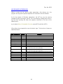
REVISION HISTORY
Revision
1
Date
May 2010
Description
Original
Author
MMB
Pub. No. 3629
CONTENTS
COPYRIGHT NOTICE
TITLE PAGE
REVISION HISTORY
CONTENTS
INTRODUCTION
PROGRAM REQUIREMENTS
TERMINOLOGY
ABBREVIATIONS
PROGRAM INSTALLATION
Viking Vision Installation
Adobe Acrobat Reader Installation
RUNNING VIKING VISION FOR THE FIRST TIME
Configuring Viking Vision
SCREEN LAYOUT
Menu Bar Area
Button Area
Menu Area
Grid Area
Connection Area
Tool Tips Area
Navigation Area
Application Information Area
Alarm Log Area
Canvas Area
Stop Button Area
CONNECTING TO VIKING
PARAMETER ORGANISATION
DISPLAY OF PARAMETERS IN DISPLAY MODE
DISPLAY OF PARAMETERS IN EDIT MODE
EDITING PARAMETERS
Graphical Editing
EDIT WARNING MESSAGES
Pub. No. 3629
RELOADING PRESET VALUES INTO VIKING
Setting Working Parameters To Their Working Preset Value
Setting Working Preset, High And Low Range To Their Factory Values
RETRIEVING PARAMETERS FROM VIKING
SAVING PARAMETERS FROM VIKING TO FILE
LOADING PARAMETERS FROM FILE TO VIKING
ALARMS
PRINTING
STOP BUTTON
GRAPHICS CANVAS
Creating A New Canvas Page
Saving A Canvas Page
Renaming A Canvas Page
Deleting A Canvas Page
Loading A Canvas Page
Navigating Around The Canvas Pages
Adding Graphics To The Canvas Page
Moving The Position Of The Graphic
Removing A Graphic From The Canvas Page
Changing The Type Of Graphic Parameter Representation
SECURITY
Setting The Password Level
Changing Passwords
Viewing Parameter Password Levels
Changing Parameter Password Levels
Changing Sub-Menus Parameter Password Levels
BOOTSTRAP LOADING
Setting The Viking Ready For Loading
Setting Viking25 To Bootstrap Mode
Loading The Software Into The Viking
Bootstrap Loader Errors
KEYBOARD INTERFACE
FAULT FINDING
CUSTOMER SUPPORT
LICENSE AGREEMENT
Pub. No. 3629
INTRODUCTION
Viking Vision is a PC based tool which has been developed to allow easy access
to adjustable parameters and status information in the Viking product range.
Viking Vision offers the following features to the user:
•
•
•
•
•
•
•
•
•
All parameters are grouped and presented in a tree structured menu.
Parameters can be edited and displayed graphically.
Status information can be displayed graphically.
Alarms are displayed and logged in chronological order of event with the
ability to be reset.
Parameter and alarm information can be printed in a number of different
formats.
Parameters can be downloaded from one Viking and stored or loaded into
another unit.
Information can be presented graphically on up to 256 user defined canvas
pages.
Sounds can be allocated to particular events (e.g. alarms).
Uploading of application software into Viking products.
To support all of these features Viking Vision has been made highly configurable.
This allows for customisation of the program’s features for an individual contract
or operator’s needs. Each contract or application has its own unique Contract
Configuration File (CCF) which is loaded into Viking Vision. The CCF file contains
the settings required to configure the presentation and adjustment of data. (An
optional Parameter file (PAR) can be used to store parameter values from the
application.)
6
Pub. No. 3629
PROGRAM REQUIREMENTS
Viking Vision has been designed to allow operation from either desktop or
notebook computers with the following minimum specification:
•
•
•
•
•
•
•
•
•
Intel Pentium II 233 processor
64MB RAM
1024 x 768 screen resolution (high colour – 16 bit)
Windows 98 SE, Windows ME, Windows 2000, Windows NT, Windows XP,
Windows Vista, or Windows 7
One free RS232 port or USB to RS232 adapter port (for comms to Viking)
One parallel or serial port (if alarm printing is required)
Soundcard and speakers (if sounds are required)
60MB hard disk space
Mouse or other pointing device
7
Pub. No. 3629
TERMINOLOGY
The following terminology has been used in this manual:
•
[]
refers to the path of a file or files on the computer
e.g. [c:\] refers to the root directory on the C drive,
[d:\my files] refers to the directory ‘my files’ on the D drive.
•
Menu>
refers to a menu/menu item contained within the program
e.g. Menu>Embedded>Connect refers to the ‘Connect’
function from the ‘Embedded’ menu at the top of the screen.
•
Area
refers to a menu Area of the screen
e.g. Button Area refers to the section of screen containing the
mode selection buttons.
•
Mode
refers to the mode in which the program is operating
e.g. Edit mode refers to the program state as one which allows
editing of menu parameters.
8
Pub. No. 3629
ABBREVIATIONS
The following abbreviations have been used in this manual:
•
PC
personal computer
•
CD
compact disk
•
RAM
random access memory
•
MB
megabyte
•
PAR file
parameter file
•
CCF file
contract configuration file
9
Pub. No. 3629
PROGRAM INSTALLATION
Viking Vision Installation
Insert the CD marked ‘Viking Vision 3’ into the CD / DVD drive of the computer.
button and select ‘Run’. Type in [x:\setup.exe] where ‘x’ is the
Press the
drive letter allocated to your CD / DVD ROM drive and press return.) Follow the
instructions on the screen.
In addition to the Viking Vision program, you should be in possession of a CCF
file for the Viking/s you intend communicating with. This file may be copied and
stored on the computer in any location.
Note: It is recommended that the CCF file is stored in its own directory on the
drive. If a PAR file is to be used, it should also be copied into the same directory
as the CCF file.
If you have received any graphic DLL files, these should be copied into the
directory [\bin] which resides in the Viking Vision directory that was created
during program installation.
In order to access help within the program, Adobe Acrobat Reader should be
installed onto the computer (see section titled Adobe Acrobat Reader Installation
for details of how to do this.)
10
Pub. No. 3629
Adobe Acrobat Reader Installation
A copy of Adobe Acrobat Reader (release 4.05) Installer is stored on the Viking
Vision CD in [\Acrobat Reader Installer]. This may be used to install the reader
program onto the computer in any location.
Alternatively an existing installed copy of the program may be used, in which
case a new installation is not necessary. Note: if an existing version is used then
it should be version 4.05 or later.
If a later release of the Acrobat Reader is available, it is suggested that it is
installed onto the computer and used in place of release 4.05.
Installation of the program from CD can be initiated by:
•
running the program [\Acrobat Reader Installer\ rs405eng.exe] from
Windows Explorer
or
•
button, selecting ‘Run’ and typing in [x:\Acrobat Reader
pressing the
Installer\ rs405eng.exe] where ‘x’ is the drive letter allocated to your CD
ROM and press return.
In ether case the installation instructions on the screen should be followed.
11
Pub. No. 3629
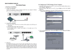
RUNNING VIKING VISION FOR THE FIRST TIME
Ensure that the Viking Vision cable is connected between the Viking and a serial
port on the computer. Make a note of the computer serial port number.
Viking Vision can be started by double clicking on the desktop icon or
button and selecting the icon in the
alternatively, by clicking the
‘Programs’ section of the menu that appears.
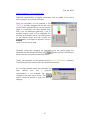
When started, a dialogue will
prompt you to select the CCF file
that is to be used for this Viking.
The appropriate file must be
selected from a directory on the
computer. When a selection has
button
been made the
should be clicked.
A second dialogue will prompt you to select a
PAR file. One must be selected from the list
button
shown on the screen and then the
should be clicked.
Note: if only the ‘Factory PAR’ PAR file is available
then it should be selected.
Viking Vision will now continue onto the main screen.
12
Pub. No. 3509
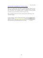
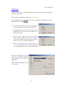
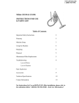
Configuring Viking Vision
When Viking Vision is run for the first time, the program needs to be configured.
This process is detailed below:
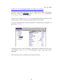
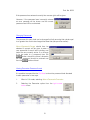
1. Select Menu>Options>Alarm print. The following dialogue will be displayed
associated with the printing of alarms as the program receives them. When
the settings have been configured click
Enable/disable printing
of alarms as they arrive
by ticking this box
Set the length of the printer page
Select the printer port which
will be used to print out alarms
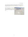
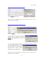
2. Select Menu>Options>Port. The following dialogue will be displayed
associated with the communications to the Viking. When the settings have
been configured click
Select the serial port
which will be used to
communicate with
the Viking
13
Pub. No. 3509
3. Select Menu>Options>PDF Reader. The following dialogue will be displayed
associated with the location of Adobe Acrobat Reader. When the settings
have been configured click
Enter the complete path
for the Adobe Acrobat
Reader program.
This may be selected
by either typing it in
directly or clicking the
button and then
selecting the program
directly from the computer’s
directory structure
14
Pub. No. 3629
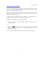
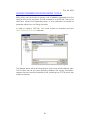
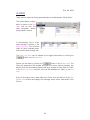
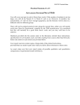
SCREEN LAYOUT
Viking Vision has been designed to present a common screen layout to the user
whether editing parameters, viewing status information or looking at alarms.
When the program is first run a screen similar to that shown below should
appear:
This can be broken down for description into the following areas:
1. Menu Bar Area
The menu bar allows access to the
various program functions.
15
Pub. No. 3629
2. Button Area
Buttons are presented
that
allow
direct
movement into any one of
the three modes of
operation – parameter Edit, status Display and Alarms and also fast access
to graphics canvas and alarm functions.
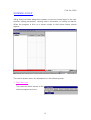
3. Menu Area
All editable, status or alarm parameters are
presented in a menu tree format. This allows
parameters of a similar type to be grouped
together
4. Grid Area
Each parameter within a menu will
appear in the grid area. If any menu
contains more parameters than the grid
can show, a scroll bar will automatically
appear.
16
Pub. No. 3629
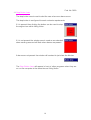
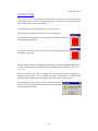
5. Connection Area
The connection area displays one of two
indicators – either a red panel with the
words ‘NOT CONNECTED’ to indicate that
communications between Viking Vision and Viking are not established, or a
green panel with the words ‘CONNECTED’ to indicate that communications
are established.
6. Tool Tips Area
This area will display simple help information or
tips associated with the cursor position on the
screen.
7. Navigation Area
This area allows
control of the
graphics canvas when in either Edit or Display modes of operation.
8. Application Information Area
Information about the
specific application can
be viewed in this area including identification, serial number and Viking
software release status.
17
Pub. No. 3629
9. Alarm Log Area
Alarms are displayed in chronological
order of status change in this area.
The area also doubles as the Canvas
Area when in Edit or Display modes of
operation.
10. Canvas Area
Parameters can be placed and
displayed in graphical form onto one of
256 canvas pages in this area.
The area also doubles as the Alarm
Log Area when in Alarm mode of
operation.
18
Pub. No. 3629
11. Stop Button Area
The stop button area is used to alert the user when new alarms occur.
The stop button is configured for each contracts requirements.
If it is present then clicking the button can be used to stop
the engine from within Viking Vision.
If it is not present the window area is used as an extended
alarm warning area and will flash when alarms are present.
If alarms are not present the window will contract to just show the title bar.
The Stop Button Area will appear in front of other programs when they are
run on the computer at the same time as Viking Vision.
19
Pub. No. 3629
CONNECTING TO VIKING
The Viking Vision Communications Cable must be connected between the
Viking and the Viking Vision computer prior to connection. Also ensure that the
Viking is powered.
Run the Viking Vision program and select the CCF and PAR file allocated for the
Viking as described in Running Viking Vision For The First Time.
Select Menu>Embedded>Connect. This initiates the communications process.
The version and issue of software will be checked between the Viking and Viking
Vision to ensure that the correct CCF file is being used.
If differences are seen then a
warning is displayed. If an incorrect
CCF file has been chosen then the
Load New Code button allows for
exiting and starting with the correct
file. If incorrect code is loaded the
Load New Code button allows for
bootstrapping the correct software
into the Viking.
Note: the CRC value is always 0.
If communications are not established correctly
then a warning will be shown.
Assuming that communications are healthy,
information about each parameter will be
obtained from the Viking by Viking Vision. This
may take some time according to the number
of parameters used in the specific application.
A message will be displayed indicating that the
process is in progress.
20
Pub. No. 3629
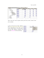
Once all the information has been retrieved, Viking Vision will check that the
values for preset , high and low ranges for each parameter match those defined
in either the ‘Factory PAR’ or specifically chosen PAR file according to the one
that was loaded.
The columns marked PAR. indicate the value from the PAR file, those marked
Emb. are the values from the Viking (embedded system).
A choice is presented that gives the option to continue with those already in the
or to load into the Viking those from the PAR file
Viking
.
Once this process is complete, the Connection Area will display the following:
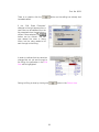
It is now possible to set the contract identification to the embedded system.
and
Click the Edit mode button
select the Menu>Embedded>Set ID option.
This will display the Set The Embedded ID
dialog. This shows the current embedded
system values for the contract indentification.
21
Pub. No. 3629
It is now possible to set the Contract ID and the Unit Serial Number for the
embedded system. When the details have been added clicking Set will save the
values to the embedded system.
A dialog will then be shown
warning of the need to
perform a full save to retain
the newly set contract
identification.
22
Pub. No. 3629
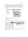
PARAMETER ORGANISATION
Parameters within the Viking have been grouped into a treelike structure so that similar types of parameters, or
parameters associated with a certain function appear
together in sub-menus. This is similar to the storage
structure of files in folders on a computer’s hard disk drive.
The Menu Area on the left-hand side of the screen shows
the parameter menu structure. Just as the menu controls
and are used to expand and contract file menus within
Microsoft Windows Explorer, they are used in Viking Vision
to expand and contract parameter menus in the same
manner.
to the leftE.g. in the example on the right above, the menus marked with a
hand side can be expanded to show their own sub-menus. Those marked with
a are already expanded and can therefore only be contracted.
Again, refering to the example to the right above, ‘Display Menu’ is described as
the root or top-level menu just as [C:\] might be on a hard disk drive. In the case
of Viking Vision there are three root menus: ‘Display Menu’, ‘Edit Menu’ and
‘Alarm Menu’.
The dark blue menu highlighting shows the menu which is currently selected.
23
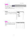
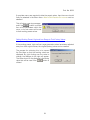
DISPLAY OF PARAMETERS IN DISPLAY MODE
Pub. No. 3629
In order to view status parameters, Display mode must be entered. This can be
done by clicking the
button in the Button Area. Alternatively,
Menu>Mode>Display can be selected.
Once in Display mode, the Menu Area on the left-hand side of the screen can be
used to select the menu containing the parameters to be viewed.
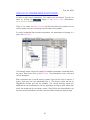
If a menu is selected that contains parameters, the parameters will appear in a
grid in the Grid Area.
The example above shows the display of parameters contained within the menu
‘This Engine’ in the Grid Area. The parameter’s name, value and unit are
displayed.
Each parameter value is updated at one-second intervals.
24
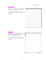
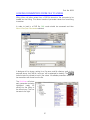
DISPLAY OF PARAMETERS IN EDIT MODE
Pub. No. 3629
In order to edit control parameters, Edit mode must be entered. This can be
done by clicking the
button in the Button Area. Alternatively,
Menu>Mode>Edit can be selected.
Once in Edit mode, the Menu Area on the left-hand side of the screen can be
used to select the menu containing the parameters to be edited.
If a menu is selected that contains parameters, the parameters will appear in a
grid in the Grid Area.
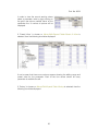
The example above shows the display of editable parameters contained within
the menu ‘Non-Linear Gain’ in the Grid Area. The parameter’s name, value and
unit are displayed.
Each parameter has a normal working preset, high and low limit as well as a
factory high and low limit associated with it. The factory values are set at
Regulateurs Europa and are not editable. The normal working values are
editable and can be adjusted to suit the application as long as their values stay
within the ranges set by the factory values. Viking Vision will automatically limit
the value of any parameter such that it remains within the factory setting range.
25
Pub. No. 3629
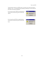
In order to view the normal working values
select a parameter value by right-clicking on
the grid in the column marked ‘Value’ on the
parameter line. A number of options will be
displayed.
If ‘Preset hi/low’ is chosen or Menu>Edit>Expand Table>Preset & hi/low is
selected, then the following should be displayed:
It can be seen that three more columns appear showing the editing range and
preset value for the parameter. Each of the four values shown for every
parameter is available for edit.
If ‘Factory’ is chosen or Menu>Edit>Expand Table>Factory is selected, then the
following should be displayed:
26
Pub. No. 3629
Again, three extra columns appear showing the factory values, however these
are not editable.
In both of the last two cases, selecting
either Menu>Edit>Expand Table>Contract
or by right-clicking on the grid in the
column marked ‘Value’ on the parameter
line and then selecting ‘Contract’ will
return the Grid Area to its normal format.
27
Pub. No. 3629
EDITING PARAMETERS
Each parameter can be edited assuming that the correct password has been
entered into Viking Vision (see section Security).
Each of the four values (normal working value, preset, high and low limit) can be
edited for each parameter by first left-clicking on the value and then selecting a
new value. If a range is exceeded then a warning message will be displayed.
A new value can be entered in a number of different ways according to the type
of parameter:
If
the
‘Edit
Numeric
Parameter’ dialogue to the
right appears then a new
value can be entered directly
into the box and then
button can be
clicked. This has now
altered the value in Viking
Vision, but the value needs
to be sent through to the
Viking. This is done by
clicking
the
button in the Button Area.
If the ‘Run Time Edit’ dialogue to the
right appears then the value can be
edited in realtime (i.e. editing has
immediate effect).
The
and
buttons will scroll the
parameter value up and down by an
amount equal to its least significant
digit. The
and
buttons will
scroll the parameter value up and
down by an amount approximately
equal to a twentieth of its maximum
and
buttons will
value. The
scroll the parameter value up and
down by an amount equal to a tenth
of its maximum value. When editing is complete
clicked.
28
button should be
Pub. No. 3629
button as the editing has already had
There is no need to click the
immediate effect.
If the ‘Edit State Parameter’
dialogue to the right appears then a
new value can be selected from the
list presented when the button is
clicked. Once selected, the
button can be clicked. This has
now altered the value in Viking
Vision, but the value needs to be
sent through to the Viking.
In order to indicate that the value has
changed but not yet sent through to
the Viking, the parameter in the Grid
Area will be highlighted.
Saving to Viking is done by clicking the
button in the Button Area.
29
Pub. No. 3629
When using either of the three methods for adjustment described above, it must
be noted that although the adjusted values end up as the normal working values
in the Viking, they are not permanently saved. In order to store the values into
non-volatile memory, the ‘Save All Edited Data’ parameter must be selected or
adjusted to any value. For Viking25, the location of this parameter is shown
below.
The
button must then be clicked in the Button Area.
During a save to non-volatile memory it important that power is not lost to the
Viking.
In the Display Menu,
the parameter ‘Saving
Status’ indicates the
progress of the save.
The value will be either
‘Complete’ in which
case
the
saving
process
is
fully
complete, or ‘Saving’
which indicates that
saving is actually in
progress. For Viking25 the saving process will take in the region of five to six
seconds.
30
Pub. No. 3629
Note:
• The indication of saving in progress for the Viking25 is a red ‘Storing
Parameters’ indicator that lights when the storing process is in progress.
• Saving to non-volatile memory will only take place when the engine is
stationary.
If in section Connecting To Viking, differences of Viking software version or issue
were seen and corrected, they should also be saved to non-volatile memory
using the process above.
Graphical Editing
Some parameters may be configured to support graphical editing. If this is the
case then when the parameter is dragged onto the canvas page, or selected
and either the
button is clicked in the Button Area, or
Menu>Edit>Graphic selected, a choice of graphical representations will be
given. The appropriate one should be selected from the list. The graphic will
appear in its own window for editing.
If a parameter is not configured to be edited
graphically then a warning will be shown.
31
Pub. No. 3629
EDIT WARNING MESSAGES
When editing parameter values, certain warning messages may be shown on
the screen according to the type of parameter. These messages must be read
and a decision made as to whether editing of the parameter should continue.
The message to the right denotes that editing
will have an immediate effect on the
parameter i.e. a save is not required to
update the working value in the Viking.
The parameter name and menu path is
indicated at the top of the message.
(Note: a save to non-volatile memory would
still be required.)
The message to the right denotes that editing
will have an effect on a parameter classed as
critical. A critical parameter is one which has a
significant effect on engine performance with
a potential safety issue if adjusted.
32
RELOADING PRESET VALUES INTO VIKING
Pub. No. 3629
When in Edit mode, working parameter values can be set back to the working
preset values, and the working preset, high and low range can be set back to
the factory values.
In order to carry out this function, Edit mode must be selected.
Setting Working Parameters To Their Working Preset Value
One of two methods can then be used to set selected parameters or complete
menus.
Setting selected parameters requires that the parameters are selected. This is
achieved either by starting to edit each parameter and then immediately clicking
either
button or
button, or by clicking the
button to select all of the parameters in the particular menu.
The parameters
highlighted.
will
then
appear
To load the preset values into these parameters either the
button can
be clicked in the Button Area, or Menu>Edit>Presets>Selected selected.
In either case a warning message will be
button
given and then the
clicked.
33
Pub. No. 3629
If complete menus are required to take the preset values, then the menu should
firstly be selected in the Menu Area. Menu>Edit>Presets>Sub-menus must be
selected.
This will show a warning message
and if the
button is clicked
then all the parameters within the
menu, or its sub-menus will be set
to their working preset values.
Setting Working Preset, High and Low Range to Their Factory Values
If the working preset, high and low range parameter values have been adjusted
away from their original values, the original (factory) values can be recalled.
The process for achieving this is to expand
the Grid Area so that the working values are
displayed. By right clicking over the value to
change, the dialogue to the right will appear.
The value shown on the dialogue is the factoy
button is
value that will be used if the
clicked.
34
RETRIEVING PARAMETERS FROM VIKING
Pub. No. 3629
When in Edit mode, there is the facility to retrieve parameter values from the
Viking after editing has taken place, but before the adjusted values have been
sent to the Viking. This is especially useful if a parameter has been adjusted
incorrectly, but no record has been made of its original value.
Note: the retrieve function will not work if editing has taken place using a ‘Run
Time Edit’ dialogue.
In order to retrieve a value (or values) from the Viking, either the
button
should be clicked or Menu>Embedded>Retrieve should be selected. Any edited
button
values that have not been sent through to the Viking using the
will be overwritten by those already stored in the Viking.
35
SAVING PARAMETERS FROM VIKING TO FILE
Pub. No. 3629
Viking Vision has the facility for saving a set of editable parameters from the
Viking to a file on the computer. The file is refered to as a PAR file. This can be
useful as a record of the application setup, or as a mechanism for transfer of
parameter values from one Viking to another.
In order to create a PAR file, Edit mode should be accessed and then
Menu>File>Save Parameters selected.
The dialogue above will be shown asking for a file name and file directory path.
The file name can be any name (following Window’s file naming convention),
however the path should be identical to that containing the CCF file which was
chosen at the start.
36
LOADING PARAMETERS FROM FILE TO VIKING
Pub. No. 3629
Viking Vision will allow values from a PAR file stored on the computer to be
loaded into the Viking. This allows transfer of parameter values from one Viking
to another.
In order to load in a PAR file, Edit mode should be accessed and then
Menu>File>Open Parameters selected.
A dialogue will be shown asking for a file name and file directory path. In the
example above, the PAR file ‘mmb.par’ will be selected for loading. The
button should be clicked to load in the values. All editable parameter values will
be overwritten with those from the file.
The Grid Area will show
each parameter as being
highlighed ready for
saving into the Viking in
the normal way. This can
be seen to the right.
37
Pub. No. 3629
The parameters saved in the PAR file are only valid for the version and issue of
software in use. To guard against the possibility of loading an incorrect PAR file
the version and issue are checked.
If an incorrect version PAR file is selected then a
warning will be shown along with the PAR files
version.
If an incorrect issue PAR file is selected then a
warning will be shown along with the PAR files
Issue.
38
Pub. No. 3629
ALARMS
There are two ways that Viking generated alarms are displayed in Viking Vision:
The current status of each
alarm is shown in the Grid
Area. Just as with any
other parameter, alarms
are grouped in menus.
A chronological log of alarm
state changes is shown in the
Alarm Log Area. This will show
when an alarm changed state,
and what the state change was.
The Alarm Log Area can be cleared of all logged information by clicking the
button in the Button Area.
Alarms can be reset by clicking the
button in the Button Area. The
Viking will respond to this request and clear any alarms (where possible). Any
alarms which are successfully cleared will log a change of alarm state to ‘Clear’
in the Alarm Log Area, and their value will be displayed as ‘Clear’ in the Grid
Area.
If any of the alarms have a state other than ‘Clear’ then the title bar of the Stop
Button Area will flash and display the message ‘Alarm active’ (see section Stop
Button).
39
Pub. No. 3629
PRINTING
In either of the three modes, parameters can be printed to provide a hardcopy
record of their values.
Printing can be initiated by selecting Menu>File>Print.
One of three options from either of the two dialogues that appear must be
selected before clicking
:
•
‘Current grid’ will print out just the parameters
from the one menu that is currently selected.
•
‘All parameters’ will print out every menu set of
parameters in turn. Each menu will appear on a
fresh printer page.
•
‘Current canvas’ will print out a copy of the
active canvas page (see section Graphics
Canvas). This option will only be shown when in
either Display or Edit modes of operation.
•
‘Alarm log’ will print out a copy of the Alarm
Log Area (see section Alarms). This option will
only be shown when in Alarm mode of operation.
When the selection has been
made the standard Windows
print dialogue to the right is
displayed.
This should be completed in the
usual manner.
40
Pub. No. 3629
If a print preview of the parameters is required rather than a full print, exactly the
same process as above should be followed except that Print Previewing can be
initiated by selecting Menu>File>Print Preview rather than Menu>File>Print.
Printer characteristics can be adjusted
and set by selecting Menu>File>Print
Setup and then by using the standard
Windows printer setup dialogue to the
right.
41
Pub. No. 3629
STOP BUTTON
The Stop Button Area performs two main roles – to inform the user that alarms
are present, and to allow a Viking Vision stop of the engine (if the contract has
been configured to use a stop button).
If a stop button has been configured for the contract :The title bar of the area will show one of two messages:
If no alarms are present then the title bar will be stable and show
the message to the right.
If an alarm is present then the title bar will flash and display the
message to the right.
If the red stop button is pushed then the engine will be immediately stopped and
a ‘Viking Vision Stop’ or ‘WIN95UI Stop’ message will be shown in the Alarm
Log Area.
Note: The engine will only be stopped if the Viking has been configured to
shutdown the engine. If an external shutdown mechanism is implimented
instead of direct control from the Viking, the engine will continue to run.
On pressing the stop button, Viking Vision will confirm
that the Viking has received the command by displaying
the message to the right.
42
Pub. No. 3629
If a stop button has not been configured for the contract :The title bar of the area will show one of two messages:
If no alarms are present then the title bar will be stable and show
the message to the right.
If an alarm is present then the title bar will flash and display the
message to the right.
43
Pub. No. 3629
GRAPHICS CANVAS
The Canvas Area allows 256 pages of parameter graphics to be created and
presented for status viewing when in Display or Edit modes (only one page may
be viewed at a time). The configuration of each page can be stored for future
use. This allows pages to be set-up to display analogue gauges representing the
various analogue inputs and outputs for example.
Any canvas page can hold graphics which are specifically associated with
Display mode parameters. The canvas page will support multiple graphical
representations of a single parameter on the same page.
A number of graphic display tools (gauges, graphs, etc) are supplied with Viking
Vision as standard. However, Viking Vision supports additional graphic DLL files
which may be provided separately with each application. If any of these graphic
DLL files have been supplied then it is essential that they be installed as per the
instructions with them prior to running Viking Vision with the applications CCF
file. If correct installation of the additional graphics is not carried out then an
error will be reported when running Viking Vision.
Note: It is important that any canvas page should be used with the CCF file that
was loaded in at the time of its creation. Under no circumstance should CCF
files and canvas pages be mixed between different applications. To prevent this
occuring each canvas page
is checked prior to loading
and will show a warning if it
is the wrong version or
issue.
44
Pub. No. 3629
Creating A New Canvas Page
In order to create a new canvas page to lay graphics onto, the
the Navigation Area must be clicked.
button in
A name for the page must be entered and
then the
button clicked. The name
must follow Window’s file naming convention.
The name entered should then appear in the
Navigation Area as shown below.
Saving A Canvas Page
A canvas page can be saved to the hard disk drive by clicking the
in the Navigation Area.
button
‘Save Canvas’ must then be selected from the dialogue shown
to the right.
It is also possible to save a canvas by selecting the Menu>File>Save Canvas
menu option when in Display mode.
Renaming A Canvas Page
A canvas page can be renamed by clicking the
Area.
button in the Navigation
‘Rename Canvas’ must then be selected from the dialogue
shown to the right.
The new canvas name must then be
entered into the dialogue to the right.
45
Pub. No. 3629
Deleting A Canvas Page
A canvas page can be deleted by clicking the
Area.
button in the Navigation
‘Delete Canvas’ must then be selected from the dialogue shown
to the right.
A warning will be given and then the
button should be clicked.
Loading A Canvas Page
Canvas files in the same directory as the CCF file will automatically be loaded
when the program is started, if they are for the same version and issue as the
CCF file.
It is also possible to load a canvas by selecting the Menu>File>Open Canvas
menu option when in Display mode.
Navigating Around The Canvas Pages
The Navigation Area provides all the controls necessary to select and navigate
around the canvas pages.
The
button brings up a list of canvas pages for selection.The
buttons select the first and last canvas pages from the list. The and
select the next and previous pages from the list.
46
and
buttons
Pub. No. 3629
Adding Graphics To The Canvas Page
Graphical representation of display parameters can be added to the active
canvas page by one of three methods:
Firstly the parameter can be selected in the
Grid Area and then dragged (with the left-hand
mouse button pressed down) onto the canvas
page. If a parameter has been defined such
that it can be displayed graphically, a list of
available graphic types will be displayed. By
scrolling up and down the list, left clicking once
on the desired image and then clicking the
button, the image will appear in its own
window on the canvas page
Secondly, rather than dragging the parameter onto the canvas page, the
parameter can be selected and then the
button clicked. The following
actions are then the same as described above.
Thirdly, the parameter can be selected and then Menu>Edit>Graphic selected.
The following actions are then the same as described above.
If in the three methods above the parameter has
been
defined
such
that
a
graphical
representation is not available, the warning
message to the right will be shown. The
button should be clicked to close the warning
dialogue.
47
Pub. No. 3629
Moving The Position Of The Graphic
A graphic image on the canvas page can be moved by left clicking on the title
bar of the image and dragging the image to the desired position.
Title bar
48
Pub. No. 3629
Removing A Graphic From The Canvas Page
Each graphic on the canvas page can be permanently removed by clicking on
the
button in the top right-hand corner of the graphic image.
Alternatively, right-clicking on the graphic image and then selecting
‘Close’ from the dialogue that appears will achieve the same result.
Changing The Type Of Graphic Parameter Representation
If a parameter has been placed onto the canvas page in a particular graphical
format, it can be changed at any stage into another type from the original list.
This can be achieved by right-clicking on the graphic image and
then selecting ‘Graphic’ from the dialogue that appears. The original
graphic symbol list will be shown. The desired symbol should be
selected.
49
Pub. No. 3629
SECURITY
A mechanism for password protection exists within Viking Vision. This protects
individual menu parameters from being edited or changed by unauthorised
access.
Five levels of protection are provided with an additional default level (Level 0)
offering minimal access privileges. The levels are numbered 1 to 5. Level 5
allows full access to all parameters and functions, Level 1 gives minimum
access (according to configuration). On entry to Viking Vision, the password
level will be the default level of 0.
Entering a password level will give access rights for that level and all levels
below.
All passwords are stored in the Viking itself so that they are transferred with the
product and are independent of the Viking Vision computer. Therefore password
entry and change can only occur when connected to the Viking.
Setting The Password Level
In order to set the password level, Menu>Password>Set Level must be
selected.
The dialogue to the right will be displayed
prompting for selection of the desired level
1 to 5.
(Note: ‘Enable bootstrap loader’ only
applies to bootstrap loading – see section
Bootstrap Loading).
A prompt will be given for the correct
password. This should be entered and then
button clicked.
the
50
Pub. No. 3629
If the password was entered correctly then access rights will be given.
However, if the password was incorrectly entered
an error message will be shown and the current
password level will be maintained.
Changing Passwords
The password for each level can be changed by firstly ensuring that a level equal
to or greater than that to be changed has been set (see previous section).
Menu>Password>Change should then be
selected. A prompt will be given to enter a
new password for each level including and
below the one currently active. If no change
is to be made to a password then the
button should be clicked, otherwise
the new password should be entered and
button clicked.
then the
Viewing Parameter Password Levels
It is possible to expand the the Grid Area to show the password level allocated
to each parameter in two ways.
1.
When in Edit mode, selecting Menu>Password>Parameter.
2.
Selecting the Parameter option from the right mouse
button menu.
51
Pub. No. 3629
Changing Individual Parameter Password Levels
Selecting Menu>Password>Parameter will
expand the Grid Area to show the
password level allocated to each
parameter. Left clicking the password level
which is to be changed will display the
dialogue shown to the right. A new value
between 0 and 5 should be entered and
button clicked.
then the
Note: A save to non-volatile memory should take place in order to semipermanently store the changes.
Changing Sub-Menus Parameter Password Levels
Selecting Menu>Password>Set sub-menus when in edit mode, with a password
level of 1-5 set, will
display the warning
dialog. This allows the
operation
to
be
canceled, by clicking
, or continued,
.
by clicking
If the operation is continued the password level
selection dialog is displayed.
Select the
password level required and then click the
button.
It is only possible to select and set password levels that are the same or lower
than the current password level. If some
of the parameters have password levels
that were higher than the current
password level a warning will be
displayed at the end of the operation.
Note: A save to non-volatile memory should take place in order to semipermanently store the changes.
52
Pub. No. 3629
BOOTSTRAP LOADING
Viking Vision supports the loading of application code into Viking products,
generally known as ‘bootstrap loading’.
ONLY AUTHORISED PERSONNEL SHOULD BOOTSTRAP LOAD VIKING PRODUCTS
AS PERMANENT DAMAGE MAY OCCUR IF THE PROCESS IS NOT CORRECTLY
FOLLOWED.
Setting The Viking Ready For Loading
In preparation for bootstrap loading, the Viking should be connected to the
computer in the same way as described in Viking Vision Installation and Running
Viking Vision For The First Time i.e. the serial cable should be connected and
the CCF stored in the correct directory on the computer.
Ensure that the Viking is disconnected from external equipment except for the
power supply and Viking Vision serial communications connectors.
Ensure the power supply to the Viking is switched off.
53
Pub. No. 3629
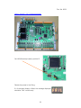
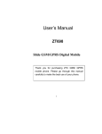
Setting Viking25 / 35 To Bootstrap Mode
Set LK2 (Bootstrap Load) to position B.
Restore the power to the Viking.
If a 4-character display is fitted, the message displayed
should be ‘FAIL’ continuously.
54
Pub. No. 3629
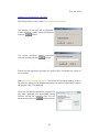
Loading The Software Into The Viking
With Viking Vision running, select Menu>Password>Set Level.
The dialogue to the right will be displayed.
‘Enable boostrap loader’ should be selected
and then
clicked.
The correct bootstrap loading password
must be entered and then
clicked.
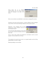
Ensure that the application program file, (project.h86), is available on a drive on
the computer.
Select Menu>Embedded>Bootstrap. This will launch bootstrap loading mode. A
file selection dialog will be displayed allowing the required application program
file, (project.h86), to be selected.
When the the required application program file
has been selected the appropriate Viking
product should be selected from the list
presented and then the
button clicked.
55
Pub. No. 3629
Viking Vision will try to establish
communications with the Viking, during
which the message to the right will be
shown.
When communications are established, a confirmation message will be shown.
According to the type of Viking product, a number of different status messages
may be shown on the screen during the duration of the program upload.
Eventually a final message will be shown
indicating the unique checksum value for the
bootstrapped program.
This should be checked against the one issued
for the version and issue of software which has
been used.
Only an exact match should be accepted as confirmation that the correct
program has been loaded into the Viking.
The bootstrap link should now be set to its original position and the Viking
powered down, and then up again
Bootstrap loading is now complete.
56
Pub. No. 3629
Bootstrap Loading Errors
•
If communication with the Viking is
not established correctly, a warning
message will be shown.
•
If the application program file, (project.h86),
selected is missing from the disk when required
by the program then a warning message will be
shown.
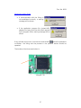
should be pressed to
If any of these errors occur, then the blue reset button
re-initialise the Viking and the process in the previous section should be
repeated.
The location of the blue reset button is:
Viking25 / 35
57
Pub. No. 3629
KEYBOARD INTERFACE
Whilst a mouse can be used to select parameters, click buttons, etc., the
program also supports keyboard operation for interaction with the software.
As for the majority of Windows applications, the ALT key may be used to
navigate through the program menus. This is achieved by holding down the ALT
key and then pressing the letter that appears underlined in the item of the
desired menu.
e.g. to select Menu>Embedded>Connect press (ALT)b and then (ALT)c.
Viking Vision also supports the use of shortcut keys. The function of these are
described below:
Key Combination
Mode
(CTRL) Home
(CTRL) End
(CTRL) Left
(CTRL) Right
(CTRL) Up
(CTRL) Down
(CTRL) PgUp
(CTRL) PgDn
(ALT) Keypad *
Home
All
All
All
All
All
All
All
All
All
All
End
All
Left
Right
Up
Down
PgUp
PgDn
ENTER
All
All
All
All
All
All
Edit
Function
Go to the top of the menu tree.
Go to the bottom of the menu tree.
Contract the branch of the menu tree.
Expand the branch of the menu tree.
Move up one level of the menu tree.
Move down one level of the menu tree.
Move up one screen of the menu tree (scroll).
Move down one screen of the menu tree (scroll).
Expands all sub - nodes of the menu tree.
Scroll the grid so that the first parameter is at the top of the
table and make it the current parameter.
Scroll the grid so that the last parameter is at the bottom of the
table and make it the current parameter.
Move the current parameter selection to be the cell to the left.
Move the current parameter selection to be the cell to the right.
Move the current parameter selection to be the cell above.
Move the current parameter selection to be the cell below.
Move the current parameter selection to one screen above.
Move the current parameter selection to one screen below.
Select the parameter currently highlighted.
58
Pub. No. 3629
FAULT FINDING
Unable To Connect To The Viking25 Or Viking35
This can affect Windows 98 SE and Windows ME on a computer that supports
the ACPI specification.
Solution
Disable the power management of the COM ports.
Backup the registry
Use the registry editor (regedit.exe) to locate the EnablePowerManagement
value in the registry key
HKEY_LOCAL_MACHINE\System\CurrentControlSet\Services\VxD\VCO
MM
Change 01 to 00 and click OK
Exit the registry editor
For more information see Microsoft Knowledge Base article Q252184
Unable To Select LPT Or COM Port In Alarm Print Dialog
When the ‘Print alarms on receipt’ check box is ticked and OK selected the
warning ‘Unable to access selected port for alarm print’ is displayed.
Solution
If this is for a COM port selection it may be already selected as the Viking Vision
COM port or another running applications COM port. Choose another COM
port.
If this is for the LPT port selection it may be that a printer has the port captured.
This can be released by choosing the End Capture on the printers properties
dialog.
59
Pub. No. 3629
Problem Printing Alarms On Receipt
If the Print alarms on receipt check box is ticked in the Alarm Options dialog and
the alarms do not print.
Solution
The printer must be directly connected to a COM or LPT port of the computer
running Viking Vision. The alarms will not print to a network mapped printer.
Problem Navigating Around Canvas Pages Using The Navigation Buttons
If a canvas page is selected clicking the left button moves to the last canvas
page and not the previous canvas page.
Solution
This is caused by renaming a canvas page from outside of Viking Vision. The
canvas pages maintain an internal copy of the canvas name that will not be
updated if the file is renamed in Explorer or DOS.
Problem Bootstrap Loading With Windows Vista
At the end of the bootstrap loading process Viking Vision may crash when the
dialogue is closed.
Solution
This seems to be an issue only occurring under Window Vista. There is no
current solution to this problem. However, the bootstrap loading process itself is
not affected by the crash so a restart of Viking Vision can safely be made with
no data loss or corruption occurring..
60
Pub. No. 3629
CUSTOMER SUPPORT
Customer training and support for this product can be provided either in
Colchester, Roden, or on-site. Contact below for further details.
Regulateurs Europa Ltd
Port Lane
COLCHESTER ESSEX C01 2NX ENGLAND
Tel: 44 (0)1206 875409
Fax: 44 (0)1206 792685
Regulateurs Europa BV
Ekkelkamp 3
9301 ZZ
RODEN NETHERLANDS
Tel: 31 5050 19888
Fax: 31 5050 13618
61
Pub. No. 3629
LICENSE AGREEMENT
SOFTWARE LICENCE ISSUED BY REGULATEURS EUROPA LTD,
REGULATEURS EUROPA ("Regulateurs Europa")
* IMPORTANT NOTICE *
THIS IS AN END USER SOFTWARE LICENSE AGREEMENT FOR
REGULATEURS EUROPA VIKING VISION SOFTWARE.
BY USING THIS SOFTWARE, YOU ARE AGREEING TO BE BOUND BY THE
TERMSOF THIS AGREEMENT.
DO NOT USE THIS SOFTWARE UNTIL YOU HAVE CAREFULLY READ AND
AGREED TO THE FOLLOWING TERMS AND CONDITIONS.
IF YOU DO NOT AGREE TO THE TERMS OF THIS AGREEMENT, PROMPTLY
RETURN THE SOFTWARE AND ANY ACCOMPANYING ITEMS.
IF YOU USE THIS SOFTWARE YOU WILL BE BOUND BY THE TERMS OF THIS
AGREEMENT.
LICENSE:
Regulateurs Europa grants you a personal, non-exclusive and non-transferable
right to use the enclosed software program (the "Software"). You will not use,
copy, modify, rent, sell or transfer the Software or any portion thereof except as
provided in this Agreement.
You may:
1. Use the Software on a single computer;
2. Copy the Software solely for backup or archival purposes;
RESTRICTIONS:
You may not:
1. Use the Software or cause the Software to be used on more than one
computer at the same time including using the Software across a network
system;
2. Sublicense the Software;
3. Reverse engineer, decompile, or disassemble the Software;
4. Copy the Software except as provided in this Agreement;
5. Copy, change, adapt, translate, transform, reproduce, alter, modify, merge or
combine the software in whole or in part with any other software or
documentation.
62
OWNERSHIP AND COPYRIGHT OF SOFTWARE:
Title to the Software and all copies thereof remain with Regulateurs Europa.
Copyright in the software shall remain at all times with Regulateurs Europa.
You will not remove the copyright notice from the Software.
You will keep the software confidential and limit access to it to those employees
who either have or need to know or are specifically engaged in its use.
WARRANTY:
Regulateurs Europa warrants that it has the right to license you to use the
Software.
Regulateurs Europa warrants that the media on which the Software is furnished
will be free from defects in material and workmanship under normal use for a
period of ninety (90) days from the date of purchase. Regulateurs Europa’s
entire liability and your exclusive remedy shall be the replacement of the
Software if the media on which the Software is furnished proves to be defective.
This warranty is void if the media defect has resulted from accident, abuse, or
misapplication. Any replacement of media will be warranted for the remainder of
the original warranty period or thirty (30) days, whichever is longer.
DISCLAIMER:
Except as provided above, the Software is provided "AS IS" without warranty of
any kind.
LIMITATION OF LIABILITY:
THE ABOVE WARRANTIES ARE THE ONLY WARRANTIES OF ANY KIND
EITHER EXPRESS OR IMPLIED INCLUDING WARRANTIES OF
MERCHANTABILITY OR FITNESS FOR ANY PARTICULAR PURPOSE.
REGULATEURS EUROPA SHALL NOT BE LIABLE FOR ANY LOSS OF
PROFITS, STATUTORY OR OTHERWISE, PRODUCTION, BUSINESS,
CONTRACTS, REVENUES OR ANTICIPATED SAVINGS, INTERRUPTION OF
BUSINESS, NOR FOR INDIRECT, SPECIAL, INCIDENTAL OR
CONSEQUENTIAL DAMAGES OF ANY KIND WHETHER UNDER THIS
AGREEMENT OR OTHERWISE SUFFERED BY YOU OR BY ANY THIRD
PARTY. NOTHING IN THIS LICENCE SHALL LIMIT OR EXCLUDE OUR
LIABILITY FOR DEATH OR PERSONAL INJURY ARISING OUT OF THE
NEGLIGENCE OF OURSELVES, OUR AGENTS OR SUB-CONTRACTORS.
SUBJECT TO THE ABOVE, OUR LIABILITY UNDER THE LICENCE SHALL NOT
EXCEED THE LICENCE FEE PAYABLE.
INTELLECTUAL PROPERTY RIGHTS:
63
You acknowledge that all trademarks, brand names, copyrights, patents and
other intellectual property rights relating to the software shall remain the
exclusive property of Regulateurs Europa.
AUDIT:
Regulateurs Europa reserves the right to conduct or have conducted audits to
verify your compliance with this Agreement. You are required to provide us on
request a written record of the location of the software.
TERMINATION OF THIS LICENSE: Regulateurs Europa may terminate this
license without prejudice to any other rights or remedies at any time if you are in
breach of any of these terms and conditions. Upon termination, you will
immediately destroy the Software or return all copies of the Software and
documentation to Regulateurs Europa along with any copies you have made.
64