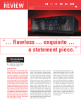
1
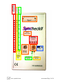
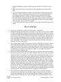
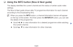
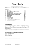
SynCheckII™
Synchronization verification and SPL tool
User Manual
Contents
Introduction
AV Error Measurement
Page 3
Page 4
First use, relative mode
SPL Measurement
Page 8
First use
Using our pink noise
Optional DVD use for SPL
Details of Operation
Page 11
switch settings, reading the display, recall of settings
Troubleshooting AV sync measurements
More Useful Tips
Guidelines for creating test signals
Page 13
Page 14
Page 16
Video and audio
Specifications
FTP address of additional test files
Using the supplied audio input cable
Page 17
Page 17
Page 18
FCC Compliance
This class A digital device complies with FCC Standards, in particular paragraph 15.103(c). Operation is subject to
the following two conditions: (1) This device may not cause harmful interference, and (2) this device must accept
any interference received, including interference that may cause undesired operation.
Changes or modifications not expressly approved by Pharoah Editorial, Inc. could void the user’s authority to
operate the equipment.
SyncheckII™ conforms to the following standards:
EN55103-1 Electromagnetic emission
EN55103-2 Electromagnetic immunity
EN61000-4-3 RF Immunity
EN61000-4-8 Magnetic field
(SyncheckII is lead free and RoHS compliant)
www.syncheck.com
user manual Page 1 of 18
DB Scale
Time Scale
“Red column”
Display/readout
Signal Detected Indicators
Quarter
frame marks
AV Mode
indicators/SPL
markers
Power
Mode
user entry
“Ahead
LEDs”
www.syncheck.com
SPL Mode
indicator
“Rel/Mask”
indicator
user manual Page 2 of 18
SyncheckII™
Synchronization verification and SPL tool
User Manual
SyncheckII™ is a unique product designed to help you accurately and efficiently evaluate
the timing relationship between audio arriving at your ears and the visuals you see. Unless sound
and image are presented by your equipment in proper synchronization you may notice poor lip
sync and you may make bad choices when placing sound with picture. With so many variables
standing in the way of perfect audio and visual synchronization, SyncheckII is designed to be the
first tool you reach for when setting up a system or anytime you want to verify proper picture
and sound synchronization. Time errors are displayed in several convenient formats.
As an added convenience during your system setup and daily operation, SyncheckII can
show you Sound Pressure Level measurements weighted by the C curve.
SyncheckII is simple to use and many of you will be inclined to skip the manual. Manual
reading is good for your health so do not stop now!
CAUTION: Syncheck test files use repeating white flashes similar to a strobe
effect. Some people have sensitivity to repeating flashes, which may cause
physical discomfort or seizures during testing! USE OUR TEST SIGNALS
ONLY AT YOUR OWN RISK! You may wish to lower room lights a bit but do
not extinguish them. Repeated flashes in a darkened room can cause discomfort or
be downright hazardous to your health. Consider yourself forewarned and
remember that you can use single, isolated flash-pips instead of repeating patterns.
While the “one per second” flash/pip patterns included on your CDR are, in our
opinion, of reasonably low risk, they are NOT risk free for some people. Do NOT
use our rapidly repeating “multi-spaced” flash patterns (download only) unless you
are willing to accept their increased health risks. It is recommended to keep your
room lights on to reduce your risks further and keep your shins undamaged.
www.syncheck.com
user manual Page 3 of 18
AV Error Measurement
SyncheckII contains a light sensor and microphone to detect light and sound. (A line
level audio input jack is also provided for situations when the microphone may pick up unwanted
sound interference.) Our test videos consist of repeated white flash frames with simultaneous
“pips” of sine tone beginning on the leading edge of each flash frame. The actual duration of
these “flash-pips” is not particularly important, rather the onset of signal is used. A single flashpip is usually enough to determine the amount of error time, but our test signals repeat
continuously to reveal intermittent errors or drifting problems. SyncheckII registers the leading
edge of each audio and image signal, shows you which was ahead of the other, and how much
time occurred between them. The results are displayed via LEDs and are updated with each
flash-pip. SyncheckII’s optical detection is very sensitivity to a wide range of visible and nearinfrared light and as a result works well with practically any display technology. The
microphone’s sensitivity is fixed to allow a wide range of comfortable and safe listening levels.
You may use our audio and video test signals supplied on CDR or DVD-R. Because we
have many more test files than can fit on a single CDR we have selected a range of commonly
used files for inclusion on your CD. You may wish to visit our ftp sight to see what else is
available (see the last page of this manual for a url.) If you purchased an optional playable DVDR you also received the full set of test files in the data area of the DVD. You can create your own
test files, if you like, as long as the signals fall within a few simple guidelines discussed later in
this manual (see page 16).
There are a range of test files available. All movie files contain video white flashes
with matching audio pips. One group of flash-pips repeat at a rate of one per second. Another
group repeats at a faster rate. Both groups are available in several different compression codecs.
All movies are standard definition and may be imported into any standard definition or high
definition video system. Each test pattern is available in NTSC, PAL, 24, and 23.976 frames per
second versions. There is no penalty for up-conversion to a high definition format, our files are
easily used at any resolution. You may need to extract the audio if your workstation cannot play
the audio directly from the movie.
“One-per-second” flash-pip files are recommended for most uses and are always
recommended for initial measurements. Their slow repetition rate allows measurement of offset
errors up to ½ second. The original Syncheck files, now called “multi-spaced”, are considerably
faster paced. The time between flash/pips varies between 5 and 12 frames with a distinctive
pattern. Once a system’s AV error is known to be less than 4 video frames, the faster pace of
“multi-spaced” patterns are best at revealing subtle drifting or intermittent errors. Also available
for download are audio-only files that match the multi-spaced patterns when pulled up or pulled
down by .1%.
Checking Audio/Video sync for the first time
1. Perform your first test with somewhat reduced lighting. SyncheckII is forgiving of
most lighting situations. Typical indoor lighting is usually okay but some bright ambient
light can affect results. We suggest that you start with lowered lights until you are
comfortable with SyncheckII’s operation. You should never need to work in total
darkness.
2. Load your workstation with appropriate audio and video test files. You should select
a video test file whose frame rate matches your system’s settings. All of our video files
www.syncheck.com
user manual Page 4 of 18
3.
4.
5.
6.
have audio embedded. You may extract that audio or use one of the separate audio files
(ftp), or create your own. (Please note that our audio-only files match our multi-spaced
video patterns, not the one per second files. If you need pulled-down or pulled-up audio
speeds, our audio-only files are already authored in many pulled up or down versions.)
For home theater or away-from-the-studio work, we also sell a playable DVD test disc, in
PAL or NTSC standards. Please note that DVD players are known to introduce all
manner of sync problems during playback and cannot be relied upon as a sync
“reference” for other components. Our DVD is intended to help align a complete system,
such as a home theater, where the player, display, and other components always function
together.
Turn on SyncheckII and push the Mode switch to the up position, toward the 4 red
LEDs just above it. One of those LEDs will light to show the current display mode.
Cycle through settings by momentarily pushing the Select switch down a few times.
Select the setting that most closely matches your video system frame rate. An NTSC user
(29.97) should select “30”, a PAL user should select “25”, 23.974 and 24 users should
select “24”. We do not recommend starting with milliseconds, “MS”, because the
maximum time that can be displayed is much shorter than with a frame rate setting. It is
best to use milliseconds only after you have verified that the offset is less than 159
milliseconds, about 4 video frames.
Play the test audio through your system at a comfortable level. SyncheckII’s
microphone is sensitive and allows a wide range of playback volume. The level into
SyncheckII must be high enough to flash the upper green “A” LED in exact step with the
audio pips. The microphone may pick up unwanted ambient or handling noises that can
affect readings. You may alternately plug in an unbalanced signal line from your console,
workstation, DVD player, or an amplified microphone signal via the mini jack. Signal
level is not particularly important as long as it is between 50 millivolts and around 3 volts
(approximately -24dbu to +10dbu). Any pro or semi pro gear should be able to meet this
requirement easily. Our supplied test pips are 3kHz sinetones. We recommend using
tones between 1kHz and 6kHz.
Point SyncheckII toward your flashing video display. The upper yellow “V” LED
should flash in exact step with the video display. If it does not, try moving closer to or
further from the display or lowering the ambient light level. SyncheckII contains an
optical sensor that “sees” your video display. It is sensitive to nearly the entire visible and
infrared spectrum. Because the sensor is very sensitive to all light we suggest that you
work in low light until you get a feel for how much ambient light is okay. If ambient light
level is too high SyncheckII may detect inaccurately or not at all. Normal “living
quarters” lighting (not fluorescent) is usually fine as long as most of the light to directly
fall on the sensor is from your video display. The sensor is recessed within the case to
help achieve this. Distance from the video screen is not particularly important as long as
there is enough light for the sensor to react. Most display types allow a wide latitude of
maximum and minimum distance from the screen. If you are extremely close to the
screen the “V” light may not fully extinguish between flashes. Pull away a couple of
inches until the “V” LED flashes properly. Some earlier LCD screens require extra care
due to their reduced contrast. SyncheckII is able to see many video monitors from across
the room although it may be necessary to temporarily turn up a small screen’s brightness
a bit if you are far away.
Both “A” and “V” signal LEDs should be flashing along with your flashes and pips.
Determine whether video or audio is ahead by looking at the LOWER LEFT green
and yellow LEDs. If the yellow LED is lit, the video flash is ahead of audio. If the green
www.syncheck.com
user manual Page 5 of 18
LED is lit, the audio pip is ahead of video. Both will be lit if the flash and pip are within
approximately ½ millisecond of each other.
7. Read the amount of flash-pip offset. One or two LEDs in the red column will be lit, one
blinking and the second steady. One or both LEDs may jump from one digit to another
with each flash-pip. Together both are used to read the time value. For Frames readings,
the steady LED indicates the number of frames and the blinking LED indicates 1/16th
fractions that are added to the frame value to make up the total time. For example if you
see a steady “3” and a blinking “11”, the offset is 3 and 11/16th frames. If there is only
one LED lit, there is no steady LED, it means that the same digit is required for both a
steady and blinking indicator. If you see only a blinking “3”, the offset is 3 and 3/16th
frames. For Milliseconds indication, the steady LED indicates tens of milliseconds,
while a blinking LED indicates single milliseconds. For example if you see a steady “9”
and a blinking “3”, the error is 90 plus 3, or 93 milliseconds. The blinking value will
always be between 0 and 9 while the steady can be from 0 to 15 (actually, 0 to 150 since
you multiply the steady value by 10). The maximum number of milliseconds that can be
displayed using this scheme is, therefore, 159.
8. If you are working in a reverberant location it is possible that measurements may be
affected by long reverb decay (echo) in the room. Normally, after a flash-pip event has
been detected SyncheckII waits a short time before resetting itself for the next
occurrence. This is called “mask time”. Syncheck’s normal mask time of 137
milliseconds allows reliable detection of flash-pips separated by only a few picture
frames, when used in typical sound rooms with well controlled reverb characteristics.
Longer room reverb or echo characteristics combined with ambient noise may require a
longer mask time to prevent false sound triggers. Invoke a long mask time by pushing
and holding the Select switch toward the front of the unit. As long as the switch is held,
the longer mask time is 457 milliseconds, almost ½ second. Our one-per-second flash-pip
files work well under these circumstances. Multi-spaced movies are not suitable with
SyncheckII’s long mask time
Relative Display
It is possible to enter an offset to SyncheckII’s Audio/Video (hereafter “AV”) error
measurement, a value that will be added or subtracted from the actual measurement before the
result is displayed. SyncheckII will then show only the deviation away from the offset time you
entered. Your entered offset is saved and may be restored the next time SyncheckII is turned on
by holding the Select switch UP toward the unit’s front when switching on.
Before entering a relative offset, be sure SyncheckII is first placed into one of the
AV error modes (with the Mode switch up). Then set the Mode switch to center position.
Setting the Mode switch to center always enables data entry, but what kind of data will be
entered is based on whether the switch was previously up or down. Since the switch was just up,
one of the four red mode LEDs will blink to indicate user entry is now enabled. The red column
with yellow and green “Ahead” LEDs now display your user-entered offset, in the same way an
AV sync error measurement is shown. Change the entered offset by pushing the Select switch up
or down. Hold it for auto-repeat. (Auto-repeat speed increases when the switch is held for more
than a couple of seconds.) When pushing the select switch UP you will be changing the value
towards video ahead. When pushing it DOWN you will be changing the value toward audio
ahead.
Whenever a non-zero offset value is entered (or recalled from memory at power on), the
yellow “Rel/Mask” LED will rapidly wink to remind you the display is relative, not absolute.
www.syncheck.com
user manual Page 6 of 18
You can quickly clear the offset to zero (and return to absolute readouts) by turning SyncheckII
off and on again without holding the Select switch.
You may enter the offset value in one time division mode and then switch to display
relative AV error time using a different time division. For instance, you might wish to enter an
offset in frames+fractions then switch to display the relative AV error time in milliseconds. This
would be an easy way to enter an exact number of video frames as an offset yet display the
relative synchronization error in milliseconds, without having to convert frames to milliseconds.
The new offset value you just entered is not actually saved until you push the Mode
switch away from center position, in either direction. (It would not be saved if you turned the
power off before moving the Mode switch.) A previously-saved relative value is only restored
when you hold the Select switch UP as you switch power on. Otherwise, the relative offset
value is cleared to zero at power on.
www.syncheck.com
user manual Page 7 of 18
Sound Pressure Level Measurement
Sound Pressure Level meters are designed to do one thing, measure the amount of
acoustic energy that strikes their microphone’s diaphragm. This makes them immensely helpful
in setting the playback volume of loudspeakers in editing and mixing environments.
SyncheckII’s microphone has a very small diaphragm with surprisingly linear response. When
installed flush (or nearly flush) within our case it becomes a directional pressure zone
microphone. Frequency sensitivity is affected also. For SPL measurements we alter circuit
response to provide a C weighted measurement curve. You can directly read an SPL value
between 75dbC and 90dbC on the red column, in ½ db steps. We use true RMS detection, the
most accurate method, with a suitably long integration time to give a smooth and steady readout
with pink noise. It is interesting to note that most acoustical calibrators supply sine tones for
microphone and SPL calibration, while pink noise is used almost exclusively to align playback
speaker levels (and frequency response criteria). True RMS detection is required for accurate
readings of pink noise yet many inexpensive meters can show only a mathematical average
value, a technique that fails by some amount on non-sinetone signals. The error can be more than
a db with noise, depending on the particular source being measured. Even though pink noise is
not a sine tone, volume measurements of pink noise are usually treated in the same manner as
sine tones. (For example, “That channel is one db too soft.”) It is therefore important to measure
pink noise as accurately as possible. True RMS detection is a more expensive measurement
technique but provides a more correct result. It is a standard technique in high end measuring
equipment, and SyncheckII!
SPL readings are taken from the microphone only, line inputs are ignored. Temperature
will affect readings. SyncheckII is calibrated at 75°F (24°C) and we recommend taking SPL
measurements between 68°F and 86°F (20°C and 30°C) for best accuracy. See specifications for
more information.
A successful speaker/room installation requires far more time, skill, knowledge of
acoustics, and problem solving than this manual can cover. Setting playback volume with an SPL
meter is merely the final step in that series of events. It is a step that should be repeated
regularly.
Checking SPL for the first time
SPL measurements are quite simple. Push the Mode switch down to light the green
“dbC” LED. Hold SyncheckII at the listening position and point toward your speaker. Read SPL
directly using the LED scale where the bottom LED indicates “75” and the top indicates “90”.
Actually, the lowest value printed on SyncheckII’s scale is “76” next to the second-lowest LED.
The lowest LED is 75. Each LED represents one full db change while ½ db increments are
displayed using two LEDs. For instance, if only the 80 LED is lit, the actual value is between
80.0 and 80.4dbC. If both the 80 and 81 LEDs are lit, the actual value is between 80.5dbC and
80.9dbC.
It is best to hold SyncheckII (or any SPL meter) at arms length to reduce the effect of
your body on its measurements. SyncheckII’s microphone is somewhat directional due to its
mounting within the case and we recommend pointing it more or less directly toward the speaker
being measured. Perfect aim is not necessary but deviations of more than about 20 degrees can
cause slightly reduced SPL readings, normally less than a db, depending on the amount of
acoustic energy above 1KHz being measured.
www.syncheck.com
user manual Page 8 of 18
There is a handy SPL marker formed by the four red LEDs above the mode switch. These
LEDs are used to indicate when the measured SPL is very close to a value you can set. When
measured SPL is within approximately 1 db on either side of the set point one or more of the four
mode LEDs will light. When all four LEDs are lit the measured SPL level is within about .2 db
of your set point. You may change the set point after moving the Mode switch to center position
(assuming SyncheckII has already been in SPL mode). The dbC light will begin flashing to
indicate user entry is enabled. The column of red LEDs shows your set point in the same way an
SPL reading is displayed. Use the Select switch, pressing up or down, to move the set point to a
different dbC level. Push the Mode switch down again to continue measurements, and to save the
new set point. The new set point will be restored at each power up.
Using our pink noise files
We have taken considerable care while creating our pink noise files. The full bandwidth
version contains the same energy between 20 Hz and 20 kHz as a 1000 Hz sine tone of -20dbfs,
when each is measured with a true RMS meter. All of our recordings are referenced to a -20dbfs
standard. We have also created a limited bandwidth pink noise derivative with sharp cutoffs at
300 Hz and 3000 Hz. Its level has been increased to show the same reading on a C-weighted true
RMS meter as our full bandwidth noise. Thus, a quality C-weighted SPL meter will read them
equally in a near-perfect playback environment.
SPL measurement of full bandwidth pink noise requires a full bandwidth playback
system. We prefer to compare the readings obtained with both types of noise. They should be
approximately equal on a reasonably flat playback system. Poor low frequency speaker/room
performance can affect the SPL measurement quite a bit because most of the energy in pink
noise is contained in the lower couple of octave bands. A deviation of just a few dbs with
frequencies below 80 Hz can affect the SPL readings noticeably even though the system overall
is nearly perfect in other ways. If some speakers in your setup are not capable of reasonably
linear response to below 30 Hz you should use only our filtered narrow bandwidth pink noise for
final SPL adjustment of those speakers.
It should be noted that most filtered pink noise recordings readily available or built into
professional equipment do NOT provide level compensation to match the C-weighted reading of
full bandwidth noise. Ours does. We are puzzled at other manufacturer’s decisions in this regard.
They generally give you narrow bandwidth noise that is not level adjusted at all or is adjusted for
equal energy using a FLAT measurement curve. Those same manufacturers then go on to tell
you to use a C weighted meter to set speaker levels. This is where we scratch our heads. They
ignore the fact that your C weighted meter will not provide the same readings as the nonweighted meter they used to author their recordings. We have authored our recordings so that no
mental calculations need be made. Play our filtered pink noise and set your playback volume to
read the level you desire.
If you do not have our optional playable test DVD, skip the remainder of this section.
Setting proper system gain and speaker level involves making several informed choices
to achieve a good result. We assume you already know what you are doing! If you are not
experienced with mixing room acoustics and playback system setup we encourage you to seek
advice from someone who is.
In addition to AV sync tests, our optional DVD provides two pink noise sections and a
level setup section in both DTS and AC3 formats. Level setup provides a 1000 Hz sine tone on
all channels simultaneously (50 Hz on LFE), all at -20dbfs level. Dialnorm is set at -31db (unity
gain) and you must disable any compression or “late night” consumer playback modes. If
required, adjust playback gain between the DVD player and your playback equipment to match
www.syncheck.com
user manual Page 9 of 18
your system’s headroom. This level is often referred to as “reference level” or “zero VU”. We
provide a sine tone specifically for this purpose to allow accurate and steady meter readings
during gain adjustment. You may wish to check both your AC3 and DTS decoders for proper
gain and sine tone levels. They should be the same. Once satisfied, move on to the pink noise
sections.
One of the two pink noise sections provides full bandwidth noise, for speaker/room
equalization. The other pink section provides narrow bandwidth noise for easy and accurate
speaker level adjustment. For both, dialnorm is set at -31db, unity gain. You must disable any
compression or “late night” modes. Do NOT change any initial gain settings you have already
established with the 1000 Hz sine tone, our pink noise files are already at the proper levels
relative to that sine tone. By changing audio tracks you can switch the noise to each speaker
channel. The Low Frequency Effects channel (“subwoofer” is a popular and incorrect term)
requires special care. We have created two pink noise derivatives specifically for the LFE
channel, one included in the full bandwidth section and the other in the narrow bandwidth
section. Their levels have been lowered by 10 db and thus are intended to be played though an
LFE channel that includes the standard 10db gain boost (ALL DVD playback formats, including
AC3 and DTS, require this boost.) Because our two LFE signals are different in each section
they require some explanation. It is very important that you understand the difference!
The LFE signal included in the full bandwidth section is simply a 20 Hz to 120 Hz
extract of the full bandwidth recording, but reduced in level by exactly 10db. When LFE
playback is properly adjusted, this signal will excite each lower frequency band on your realtime analyzer to the same power level as measured from your other speaker channels. On a
perfectly flat system, each band should read exactly the same value according to your real-time
analyzer. A simple SPL meter, including SyncheckII, should never be used to set the LFE
playback gain using this section.
The LFE signal included with the filtered bandwidth section is intended as an aid to those
who may not have access to a real-time analyzer. IT IS NOT THE SAME LFE SIGNAL THAT
IS USED IN THE FULL BANDWIDTH SECTION! It is a 20hz to 80hz extract (NOT 20 to
120hz!) level-adjusted to provide the same acoustic energy as our filtered pink files, when played
through the LFE channel’s standard 10db gain boost AND MEASURED ON A
SYNCHECKII™ (or any C-weighted SPL meter). In other words, when using the filtered pink
noise section you should set the LFE speaker to read the same dbC as each of the other front
speakers.
REPEAT…It is very important to understand the distinction between the two LFE signals
on our DVD. They contain different signals at different levels for different measurement
techniques. To use the full bandwidth section you MUST have a real-time analyzer and be able
to adjust each speaker for proper playback response in each frequency band. Use the filtered pink
section to set, or double check the setting of, each speaker channel’s overall SPL. You MUST
use a C-weighted SPL meter, and it is assumed that your LFE speaker can energize your room
with good linearity between 20 and 80 hertz. Adjust each channel individually to show the same
SPL readout. (The LFE channel should read the same as the center speaker, for instance, using
our narrow band pink section.) Other manufacturer’s pink noise recordings that were not created
with C-weighted measurements in mind will yield wrong results if used in the same manner.
The exact SPL value that you set your speakers for is situation dependent. That choice,
and proper use of a real-time analyzer, is beyond the scope of this manual. We encourage you to
research the subject further. Please do not call us about it.
www.syncheck.com
user manual Page 10 of 18
Details of Operation
Toggle switches select operating modes
The right-most toggle switch, the Mode switch, has three positions that select one of three
primary operating modes. When the switch is fully pushed up, A/V timing errors are displayed.
Time is shown as full frames+fractions at standard 24, 25, or 30 (29.97) frames per second rates,
or as milliseconds. Cycle through the 4 time division choices by momentarily pushing down the
Select switch. A corresponding red LED above the Mode switch will light.
When the Mode toggle switch is pushed down the display shows Sound Pressure Level in
C-weighted decibel values. In this mode the green “dbC” LED is steadily lit.
The Mode switch can also be set to center position to enable user entry for the mode you
were just in. For instance, if you set the Mode switch to center position after SyncheckII has
been in an AV error display mode, you can then set a time offset value for relative display.
Similarly, if you have been measuring SPL and then click the Mode switch to center position, the
user-entered SPL value can be set. When the Mode switch is centered a corresponding mode
LED will blink rapidly and the red column will show the value being entered. The value is
changed using the Select switch. By pushing it up or down, the parameter value is incremented
or decremented. By holding Select a few seconds the speed of entry is gradually increased.
Reading the Display
There are two types of data displayed on the LEDs, Audio/Video (“AV”) timing errors
and sound pressure level readings. Two LEDs near the top of the case indicate the presence of
light and sound at the sensors. These two LEDs operate directly from their associated sensor
circuits at all times. All other LEDs are under microprocessor control.
When AV error time mode is selected the column of 16 red LEDs indicates values
between 0 and 15, where the lowest LED corresponds to zero and the upper-most corresponds to
15. There is a scale printed next to the LEDs for this purpose (see page 2). Usually, one of the
“Ahead” LEDs will indicate whether Audio (green) or Video (yellow) is earlier than the other. It
is possible that both “Ahead” LEDs will be lit, indicating that audio and video are very close
together. It is also possible that neither “Ahead” LED will be lit. This happens when there is no
valid measurement to display.
During AV time display the red column usually lights two LEDs, one steady and one
blinking. Together both are used to read a time value. If you have selected one of the
frames+fractions display divisions, the steady LED indicates a number of full frames while the
blinking LED indicates additional 1/16th fractions that are added to the full frame value to make
up the total time. For example if you see a steady “3” and a blinking “11”, the time error being
displayed is 3 and 11/16th frames. When both full frame and fraction values try to light the same
LED, its blink pattern changes and it will be the only lit LED.
In a similar manner, milliseconds can be displayed. The steady LED indicates tens of
milliseconds, while a blinking LED indicates single milliseconds. For example if you see a
steady “9” and a blinking “3”, the error is 90 plus 3, or 93 milliseconds. The blinking LED will
always be between 0 and 9 and the steady from 0 to 15 (actually, 0 to 150 since you multiply the
steady value by 10). The maximum number of milliseconds that can be displayed using this
scheme is, therefore, 159.
Sound pressure level is shown on the red column in a slightly different manner. You will
notice another scale printed next to the LEDs, where the bottom LED indicates “75” and the top
indicates “90” (see page 2). Actually, the lowest value printed on SyncheckII’s scale is “76”, and
www.syncheck.com
user manual Page 11 of 18
the LED below indicates 75. Each LED represents one full db change while ½ db increments are
displayed using two LEDs. For instance, if only the 80 LED is lit, the actual value is between
80.0 and 80.4dbC. If both the 80 and 81 LEDs are lit, the actual display value is between
80.5dbC and 80.9dbC.
Recall of Modes
Whenever you select a different time division (24, 25, 30, or MS) or change between AV
error display and SPL display, several operating status bytes are saved to EPROM. These bytes
allow SyncheckII to remember its previous settings when you turn it on. When turning on
SyncheckII, the Mode switch position is always followed. If it is in its center position for user
entry mode, SyncheckII will enable entry of either the relative error offset or SPL marker based
on these status bytes. The previous time division setting and SPL marker value are always
restored. The relative error offset is cleared by default to prevent unintended relative displays.
You can choose to restore it by holding the Select switch UP when turning on SyncheckII. If you
turn the unit on but forget to hold the switch up, and your previous offset value was not restored,
the value is still in memory (available for recall) until it is overwritten by a mode change.
SyncheckII will only recall the most recent set of values in EPROM.
Display brightness and firmware version
Hold the select switch DOWN while turning power on to enter a secondary mode.
SyncheckII displays its firmware version on the red column in a way similar to time display. As
of the date of this manual’s writing our firmware version is 1.2. The left-most digit is displayed
with a steady LED and the right-most digit is displayed with a flashing LED.
You may adjust display brightness while the firmware version is showing. Set the Mode
switch to center position. Push the Select switch up or down to adjust display brightness. Battery
life can be extended somewhat with lower brightness settings. There is little difference to battery
life between the dimmest setting up to about 2/3 brightness, but battery drain can increase up to
30 percent when the LEDs are operated at full brightness.
To exit secondary mode, turn the power off.
www.syncheck.com
user manual Page 12 of 18
Troubleshooting AV sync measurement
1. Is your battery good? Battery voltage should remain above 7.5 volts at all times or you
will experience erratic measurements. Always replace the battery after 5 or 6 hours of
use.
2. Unable to get upper amber LED (video input) to light. Light levels hitting the sensor
are either too high or too low.
• Try turning up the image display’s brightness or moving SyncheckII closer to the
screen.
• Ambient lighting may be too high. Bright light will overload the sensor even though
the “V” LED remains off. Reduce ambient lighting, close curtains and doors or if
outdoors wait until dusk.
• The sensor is equally sensitive to invisible infrared light. Is there any equipment
producing infrared light such as intruder detection or hearing-impaired broadcasters?
3. Unable to get upper amber LED (video input) to extinguish, even when no video is
present. A pulsing light source is hitting the sensor.
• All lights connected to AC mains exhibit some degree of pulsing, even though our
eyes do not notice it. Lower them, and/or make certain there is no direct light hitting
the sensor.
• If you are holding SyncheckII very close to the video screen, pull away a couple of
inches.
• The sensor is equally sensitive to invisible infrared light. Is there any equipment
producing infrared light such as intruder detection or hearing-impaired broadcasters?
• Fast Fix: Try a piece of paper tape over the sensor hole to reduce light hitting the
sensor. Pierce a small hole in it with a pen or pencil to admit a little more light.
4. Unable to get the upper green LED (audio input) to light. Audio input levels are too
low.
5. Unable to get upper green LED (audio input) to extinguish, even when no audio is
playing. There is noise on the audio input.
• There could be an audible buzz in the audio source.
• There may be excessive dither noise present (above human hearing) from digital to
analog converters when several converter outputs are combined together to a single
signal, such as with summing buss mixers. SyncheckII contains a filter to reduce this
possibility.
6. Unable to get a steady time reading
• One or both steady/blinking LEDs may jump from one digit to another with each
consecutive flash-pip. This is common with many playback system configurations.
Variations within ½ video frame are generally considered acceptable. A professional
and fully gen-locked system will not exhibit any jumping digits.
• If you are using one of our multi-spaced test files and audio/video are more than 4
frames out of synchronization, a steady reading will be impossible. Try one of the
“one per second” files first, before using a multi-spaced version.
• There may be optical interference from another light source, such as fluorescent
lighting or security devices that are causing false optical triggers. We have seen
fluorescent lighting impose its own power line signature on the readings, giving the
impression that the audio and video signals were drifting apart. In truth, we were
www.syncheck.com
user manual Page 13 of 18
•
•
•
seeing the difference between our 60hz power line and the 59.97 field rate of our
video.
There may be audio noise or more than one audio signal present on SyncheckII’s
input.
If you are using a microphone, excessive room reflections or long reverb can cause
difficulties. There is a special long-mask mode that can be invoked by holding the
Select toggle switch up. The mode is released as soon as you release the toggle
switch. When this mode is invoked the yellow “Rel/Mask” LED next to the green
dbC LED will light, and both audio and video inputs will be masked, or deactivated,
for 457ms after each flash-pip, to prevent unwanted detections. We recommend this
mode only with “one per second” test signals.
Are you aiming the visual sensor accurately? Try adjusting SyncheckII’s angle to the
screen.
More Useful Tips
•
•
•
•
•
Each unit’s serial number is affixed inside the battery compartment.
Bright ambient light can temporarily overload the very sensitive sensor. If you are unable
to reduce ambient lighting enough to get satisfactory measurement stability, it may help
to reduce the overall amount of light entering SyncheckII. A quick fix is, believe it or not,
to put a piece of tape over the sensor’s hole and punch a small hole in it. This will reduce
the overall light level hitting the sensor so it may be necessary to hold SyncheckII closer
to the video image. This technique may seem a little “makeshift” but is exactly how we
deal with brightly lit mercury vapor lamps when displaying SyncheckII at trade shows.
Normally, the tactic is not needed.
If your audio signal is mostly low-frequency content (a 100hz tone, for instance, which is
not recommended but perhaps you have no better choice) it will help to raise the level
being fed into SyncheckII. Since low frequency signals have a relatively slow rise time, a
higher level will aid in detection as well as timing accuracy. Also, SyncheckII’s line input
is intentionally less sensitive to low frequency signals, so your applied level must be
raised to overcome a high pass filter.
Many video monitors begin drawing an image from top to bottom rather than presenting
the entire image all at once, a process called “scanning”. This is most easily noticed with
cathode ray tube (CRT) displays. If the display is large and SyncheckII is held close to it,
SyncheckII will most likely read only the small area directly in front of the image sensor.
Depending on the type of video signal and display characteristics, there can be up to
nearly one half frame difference when SyncheckII reads the upper left corner of a large
CRT versus the lower right corner. This is normal. With our test signals a more accurate
reading is from the upper left corner. Solid state displays may or may not use a scanning
technique. Rather than holding SyncheckII close to the screen’s upper left corner to get
an accurate reading, we recommend holding SyncheckII further away from the screen so
the sensor “sees” a large screen area. In our experience the readings obtained at a distance
compare very closely, within a few milliseconds, to those obtained from the most optimal
positions up close, and are more than accurate enough for practical purposes.
Start with one-per-second test files until the actual error times are known. Once the
system under test is known to have less than 4 frames of error, any of our test files may
be used with confidence. We provide files with different “flash-pip” repetition rates.
Different rates have different uses. Some are simple once-per-second repetitions. These
www.syncheck.com
user manual Page 14 of 18
•
•
are suitable for most purposes and provide the widest margin of error measurement.
Some 24p files use a 3-per-second rule. The remainder use flash-pips that are closer
together but not evenly spaced. With regularly spaced pulses it is possible to see a false
indication of in-sync audio and video whenever the actual timing is a multiple of the flash
rate. If the flash rate were once every 5 frames, for instance, you could see a zero
measurement display when the actual error is zero frames, 5 frames, 10 frames, and so
on. By lengthening the time between flash-pips we can reduce the likelihood of this
ambiguity, and thus we provide one-per-second files for general use. A one-per-second
rate allows a full ½ second of error measurement without ambiguity. Slow rates are not
best at revealing intermittent or drifting errors, though. Our multi-spaced patterns are
designed for that. They place flash-pips between 5 and 12 frames apart. Due to their
higher repetition rates they will more easily reveal subtly changing synchronization
errors. Their irregular spacing prevents steady false readings unless the AV error is less
than 5 frames. As just noted, our 24p files are evenly spaced 3-per-second flash-pips. We
include them to show results within a 24 to 30 frame workflow. By spacing flash-pips at
a multiple of both frame rates, exact 24 to 30 frame interpolations or conversions are
possible. 3-per-second rates allow a significant chance of mis-measurement and should
only be used when you are certain your system’s error is already less than 5 frames.
Some DVD players do not play audio in sync or may loose sync when switching between
audio tracks. It is always helpful to verify a particular machine’s operation with an analog
CRT monitor (to avoid added latency of digital processing) to know which errors are
caused by the machine and which by the display.
We have tried to make SyncheckII robust but keep in mind that all equipment is
susceptible to static damage. Please ground yourself and take normal precautions.
www.syncheck.com
user manual Page 15 of 18
Guidelines for using your own test signals.
Video. SyncheckII’s optical detection is exceptionally sensitive and responds to a wide range of
visible and near-infrared light. As a result, SyncheckII works well with practically any video
image and display technology with adequate brightness and contrast. White flashes against an
otherwise dark background make ideal visual sync markers. It is important that the image before
and after your “sync” frame be very dark so that the “sync” frame provides a sufficiently large
contrast to the surrounding frames. It is the change from dark to light that SyncheckII detects. A
“sync” frame is typically a single frame in length, but longer durations work just as well.
SyncheckII responds only to the leading edge of brightness. There must be a minimum of 137
milliseconds between each occurrence of a “flash” frame. Traditional scanned video displays
typically begin drawing their image at the upper left corner of the screen in thin horizontal strips
called scan lines. It takes only a small number of bright scan lines to be drawn before SyncheckII
detects the brightness change, which is typically between 2 and 3 milliseconds of the frame’s
electrical beginning, using a full frame white image. Anything other than full frame flashes can
introduce unintended timing ambiguities when comparing different video scan technologies.
Audio. Any signal with a sufficient positive rising attack edge will work. (This means a
negative-going pulse will not be detected until it goes “positive” to return to its starting point.)
With audio signals, absolute polarity is not always guaranteed (“phase reversal”). As a practical
matter, we like to use sine tones which have both positive and negative rising voltages.
SyncheckII will detect a sine tone within a half-cycle regardless of the signal’s polarity. A 1kHz
signal would therefore be detected within 1/2 millisecond, which is usually adequate for our
needs. Since higher frequency tones theoretically allow faster detection, we have chosen
somewhat arbitrarily to use 3kHz for our test signals. We see no worthwhile difference in
readings for any frequency tones between 1kHz and 6kHz. Frequencies below 1kHz are not ideal
but still very useable as long as the level fed into SyncheckII is raised. The built-in microphone
is sensitive to noise generated by handling of the unit. When measuring AV timing, SyncheckII
restricts audio bandwidth of the microphone circuit to between about 800hz and 6kHz. The line
input is restricted to between 150hz and 6kHz.
www.syncheck.com
user manual Page 16 of 18
SyncheckII™ Specifications
Audio Input level: between 50mv and 3v, RMS.
Connector: .097” (2.46mm) Subminiature phone plug 2 conductor, Switchcraft part #850 (supplied)
Recommended maximum ambient light level to directly strike sensor: below 20 lux
Minimum acoustic level of 3KHz pips: 66db at the microphone
Audio to video timing resolution: better than .2ms
Maximum error time display resolution: plus/minus 15 and 15/16 frames, or plus/minus 159 milliseconds
Resolution: 1/16 frame or 1 millisecond
SPL weighting: C curve plus/minus 1.5 db between 20 and 15KHz
SPL display range: 75 to 90 dbC
Battery: 9V standard alkaline (or any voltage between +8 and +16V, low ripple)
Battery Life: 6 hours continuous operation
Operating temperature: 35°F (2°C) to 120°F (49°C)
SPL temperature stability: calibrated at 75°F (24°C). Temperature variation will affect readings. Subtract ½ db from
the reading for each 20°F (11°C) drop in room temperature, add ½ db for each 20°F increase. All SPL meters
are sensitive to temperature and barometric changes and require an acoustic calibrator for best accuracy. This
information is included only as a general guide because each unit is slightly different.
Shipping Weight: 1 lb
Obtaining files via ftp
Please visit our website at www.syncheck.com for a link to an ftp server with our test files.
The url below is active as this manual is released. Internet Explorer or Fetch are
recommended. On WindowsXP, after your first visit Explorer will display the page from its
cache rather than connect to the internet. Once displayed, you will need to “Open FTP site
in Windows Explorer” from the Page menu. This will actually connect to the ftp server and
ask for your username and password (you may need to right click on the new page before
you can enter your login information.)
url - ftp://0016953.netsolhost.com
username – Syncheck%0016953
password –
The password is now provided with your purchase. Please keep a permanent record of it. IF you
experience technical difficulties, first check our website to see if the url has been changed or visit
http://www.pharoahaudio.com/ftpfeedback.html and submit the online login information request
form. Include your Syncheck’s serial number (look in the battery compartment).
www.syncheck.com
user manual Page 17 of 18
Using the supplied audio input cable
Beginning with serial number SX425, we supply input cables that contain 4 wires, with a
Kobiconn 4 conductor 2.5mm plug on one end. Previous cables contain two wires with a
Switchcraft 2 conductor 2.5mm plug. Audio signal requirements have not changed at all, only
the cable that is supplied, and either cable will mate properly with all Syncheck models.
Syncheck and SyncheckII only use the shield and tip connections. For 4 wire cables, unbalanced
audio is connected between the red wire and shield. The other two wires are not used at this time.
This diagram is of the 4 conductor Kobiconn cable.
www.syncheck.com
user manual Page 18 of 18