1
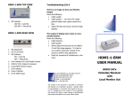
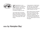
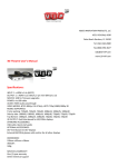
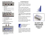
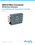
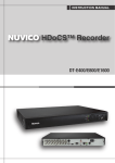
Micro-UDX User Manual APANTAC LLC, 7556 SW BRIDGEPORT ROAD, PORTLAND, OR 97224 [email protected], TEL: +1 503 968 3000, FAX: +1 503 389 7921 Micro-UDX User Manual COPYRIGHT and TRADEMARK All rights reserved by APANTA LCC, Portland, Oregon, USA. No part of this document may be reproduced in any form or by any means without written permission from the product manufacturer. Changes are periodically made to the information in this document. They will be incorporated in subsequent editions. The product manufacturer may make improvements and /or changes in the product described in this document at any time. All the registered trademarks referred to this manual are belonging to their respective companies. WARRANTY STATEMENT Apantac LLC (herein after referred to as “Apantac”) warrants to the original purchaser of the products manufactured by Apantac (the “Product,”) will be free from defects in material and workmanship for a period of three (3) year from the date of shipment of the Product to the purchaser. If the Product proves to be defective during the three (3) year warranty period, the purchaser’s exclusive remedy and Apantac’s sole obligation under this warranty is expressly limited, at Apantac’s sole option, to: (a) repair the defective Product without charge for parts and labor or, (b) provide a replacement in exchange for the defective Product or, (c) if after a reasonable time, is unable to correct the defect or provide a replacement Product in good working order, then the purchaser shall be entitled to recover damages subject to the limitation of liability set forth below. Limitation of Liability Apantac’s liability under this warranty shall not exceed the purchase price paid for the defective product. In no event shall Apantac be liable for any incidental, special or consequential damages, including without limitation, loss of profits for any breach of this warranty. If Apantac replaces the defective Product with a replacement Product as provided under the terms of this Warranty, in no event will the term of the warranty on the replacement Product exceed the number of months remaining on the warranty covering the defective Product. Equipment manufactured by other suppliers and supplied by Apantac carries the respective manufacturer’s warranty. Apantac assumes no warranty responsibility either expressed or implied for equipment manufactured by others and supplied by Apantac. This hardware warranty shall not apply to any defect, failure or damage: a) Caused by improper use of the Product or inadequate maintenance and care of the Product; b) Resulting from attempts by those other than Apantac representatives to install, repair, or service the Product; c) Caused by installation of the Product in a hostile operating environment or connection of the Product to incompatible equipment; APANTAC LLC, 7556 SW BRIDGEPORT ROAD, PORTLAND, OR 97224 [email protected], TEL: +1 503 968 3000, FAX: +1 503 389 7921 ~1~ Micro-UDX User Manual Table of Contents 1.0 What's in the Box ......................................................................................................................... 3 2.0 Key Features ................................................................................................................................ 3 3.0 Specifications ............................................................................................................................... 4 3.1. Input / Output Combinations .................................................................................................... 5 4.0 Hardware and Installation ............................................................................................................ 6 4.1. Front Panel / Panel ............................................................................................................... 6 4.2. Installation ............................................................................................................................ 7 4.2.1. Ventilation...................................................................................................................... 7 4.2.2. Mounting........................................................................................................................ 7 4.2.3. Power ............................................................................................................................ 8 4.2.4. SDI Loop Out ................................................................................................................ 8 4.2.5. IP ................................................................................................................................... 8 4.2.6. HDMI video output ........................................................................................................ 8 4.2.7. SDI video output............................................................................................................ 9 4.2.8. AA OUT ......................................................................................................................... 9 4.2.9. GPI port ......................................................................................................................... 9 5.0 MicroQ_Lite_Controller Software ............................................................................................... 10 5.1. Getting Started ................................................................................................................... 10 5.2. Running the MicroQ_Lite_Controller .................................................................................. 10 5.3. Connecting to the Micro-UDX ............................................................................................. 10 5.4. Configuring the Micro-UDX ................................................................................................. 12 5.4.1. Output Manager .......................................................................................................... 12 5.4.2. Set GPI Definition........................................................................................................ 13 5.4.3. Front Panel Definition ................................................................................................. 14 5.4.4. Preset – Save / Load .................................................................................................. 14 5.4.5. Copy Layout to other modules .................................................................................... 15 5.4.6. Write to Flash .............................................................................................................. 16 5.4.7. Set Audio ..................................................................................................................... 17 5.4.8. Quit .............................................................................................................................. 17 Appendix I ........................................................................................................................................... 18 APANTAC LLC, 7556 SW BRIDGEPORT ROAD, PORTLAND, OR 97224 [email protected], TEL: +1 503 968 3000, FAX: +1 503 389 7921 ~2~ Micro-UDX User Manual 1.0 WHAT’S IN THE BOX 1x Micro-UDX 1x Mounting Plate 1x RJ50 to DB9 cable for GPI/Tally 1x 75 ohm BNC terminator 1x DC 5V 3.2A Power Adapter 1x CD (software, manual) 2.0 Key Features Low power consumption - 12 W and Silent – No fan! Accepts 1 x auto-detect 3G SDI, HD SDI, SD SDI and Composite video signals Simultaneous HDMI and SDI outputs Decode up to 8 embedded audio per SDI input Ethernet port for Configuration Audio monitoring output – analog, HDMI Four configurable Front Panel Buttons 8 x GPI contacts: Configurable for tally or ASCII protocol Automatic aspect ratio APANTAC LLC, 7556 SW BRIDGEPORT ROAD, PORTLAND, OR 97224 [email protected], TEL: +1 503 968 3000, FAX: +1 503 389 7921 ~3~ Micro-UDX User Manual 3.0 Specifications Description Output HDMI SDI Inputs Serial Digital Video Equalization Return Loss Embedded Audio Composite Signal Level DC Offset Impedence Return Loss GPI IP Electrical EMI/RFI Power Size Mount Options Compact video Up, Down, Cross-convertor 1 x HDMI, 1 x SDI 800x480 to 1920x1200, (1080p) 50/59.94/60Hz Matching the HDMI, output resolution up to 3G 3G/HD/SD-SDI/Composite SMPTE 424M, 292M, 259M 120m at 2.97 Gbps, 140 m at 1.48 Gbps, 400m at 270 Mbps with Belden 1694A >15db up to 1.485 Gbps >10db up to 3G SMPTE-272M-A NTSC (SMPTE-170M), PAL (ITU624-2) 1V nominal 0V, ± 0.1V 75 Ω 40 db up to 5MHz 8 for tally or AXP (ASCII commands) 100 Base-Tx, AXP_Lite 12 W, 90-250V 50/60Hz Complies with FCC Part 15, Class A, CE, EU, EMC, C-tick DC 5V 3.2A 171mm W x 120mm D x 44.45mm H Magnetic Rack Mount APANTAC LLC, 7556 SW BRIDGEPORT ROAD, PORTLAND, OR 97224 [email protected], TEL: +1 503 968 3000, FAX: +1 503 389 7921 ~4~ Micro-UDX User Manual 3.1 Input / Output Combinations 720p30 720p60 1080i60 1080p60 ✓ ✓ ✓ ✓ ✓ ✓ ✓ ✓ 625i50 720p25 720p50 1080i50 1080p50 ✓ ✓ ✓ ✓ ✓ ✓ ✓ ✓ ✓ ✓ ✓ ✓ ✓ ✓ ✓ ✓ ✓ ✓ ✓ ✓ ✓ ✓ ✓ ✓ ✓ ✓ ✓ ✓ ✓ ✓ ✓ ✓ ✓ ✓ ✓ ✓ ✓ ✓ ✓ ✓ ✓ ✓ APANTAC LLC, 7556 SW BRIDGEPORT ROAD, PORTLAND, OR 97224 [email protected], TEL: +1 503 968 3000, FAX: +1 503 389 7921 ~5~ ✓ ✓ ✓ ✓ ✓ ✓ ✓ ✓ ✓ ✓ ✓ ✓ ✓ ✓ ✓ ✓ ✓ ✓ ✓ ✓ ✓ ✓ ✓ ✓ ✓ ✓ ✓ ✓ ✓ ✓ ✓ ✓ ✓ ✓ ✓ ✓ ✓ ✓ ✓ ✓ ✓ ✓ ✓ ✓ ✓ ✓ ✓ ✓ ✓ ✓ ✓ ✓ ✓ ✓ ✓ ✓ ✓ ✓ ✓ ✓ ✓ ✓ ✓ ✓ ✓ ✓ ✓ ✓ ✓ ✓ ✓ ✓ 1080p50 ✓ ✓ 1080p60 ✓ ✓ 1080p59.94 ✓ ✓ ✓ 1080i60 / 1080p60 720p59.94 ✓ Supported input format 1080i59.94 / 1080p59.94 625i / 576p ✓ 720p50 525i / 480p 525i 59.94 720p59.94 720p23.97 720p24 720p29.97 1080i59.94 1080p59.94 1080p30 1080p29.97 1080p25 1080p24 1080p23.97 1080p25sf 1080p24sf 1080p23.97sf 720p60 SDI / HDMI OUTPUTS Input / Output (SDI/HDMI) ✓ Micro-UDX User Manual 4.0 Hardware and Installation 4.1 Front / Rear Panel Figure 4-1: Micro-UDX Front Panel Figure 4-2: Micro-UDX Rear Panel 1 2 3 4 5 6 7 8 9 10 11 12 13 14 STATUS AUDIO HDMI 59.94 1 thru 4 PWR IN 1 LOOP 1,2 AA OUT 5V DC IP GPI HDMI SDI OUT Indicates detected input video Input video embedded audio detected HDMI output video format (on=HDMI, off = DVI) Output video clock (system clock) (on=59.94/29.97/23.98, off=60/50/30/24) Preset buttons Power indicator SDI/CVBS video input Loop out of video input signal Audio Monitoring output connections (Left Channel, Ground, Right channel, Ground) Power input. 5 Volt DC 3 Amp LAN Ethernet GPI/O port (adapter cable and breakout panel accessories included) Video output (configurable as DVI or HDMI video) SDI Video output (duplicates HDMI video) APANTAC LLC, 7556 SW BRIDGEPORT ROAD, PORTLAND, OR 97224 [email protected], TEL: +1 503 968 3000, FAX: +1 503 389 7921 ~6~ Micro-UDX User Manual 4.2 Installation 4.2.1 Ventilation The MicroQ is a fan-less device; therefore, it is very important the heating vents on the sides are not blocked Figure 4-3: MicroQ Venting 4.2.2 Mounting The MicroQ can be mounted 3 different ways Using the standard magnetic mounting plate Using the optiona VESA plate for mounting on the back of the monitors Using the optional rack mount to mount 2 MicroQ’s side by side Figure 4-4: MicroQ Standard Mounting Plate Figure 4-5: MicroQ Optional VESA Mounting Plate APANTAC LLC, 7556 SW BRIDGEPORT ROAD, PORTLAND, OR 97224 [email protected], TEL: +1 503 968 3000, FAX: +1 503 389 7921 ~7~ Micro-UDX User Manual Figure 4-3: MicroQ Optional VESA Mounting Plate with MicroQ Figure 4-6: MicroQ Optional Rack Mount 4.2.3 Power Make all connections prior to energizing the unit. Connect and secure the power adapter to the unit prior to plugging in or energizing the adapter. Power indicator LED will lite on unit when power is applied. 4.2.4 SDI Loop Out If only one loop out is utilized, terminate the other loop out connection with the supplied 75ohm terminator. 4.2.5 IP Note: Default IP address: 192.168.1.151 If the configuration PC is connected directly to the unit, it must be on the same subnet as the MicroQ, for example, “192.168.1.1”. If the configuration PC and unit are connected via a LAN system, the PC must be able to 'ping' the unit's IP address. This will depend upon your LAN network hardware and configuration. 4.2.6 HDMI video output The default output resolution is set to [email protected] Hz for 60Hz countries and 1024x768@60Hz for 50Hz countries to accommodate the most common display resolution. The output resolution will need to be set to obtain an HDMI display on some monitors. HDMI output will also carry the selected for monitoring audio channel pair as embedded HDMI audio. APANTAC LLC, 7556 SW BRIDGEPORT ROAD, PORTLAND, OR 97224 [email protected], TEL: +1 503 968 3000, FAX: +1 503 389 7921 ~8~ Micro-UDX User Manual 4.2.7 SDI video output The SDI video duplicates the HDMI video resolution. If the HDMI is not set to a resolution which is a standard SDI video resolution, then no SDI video will be present. 4.2.8 AA OUT The analog audio output port comes with a detachable screw terminal block. The pinout of the port is: Left Audio Channel Left Ground Right Audio Channel Right Ground The audio output can be configured to select any of the available SDI video embedded audio channel pairs (or muted). (see software chapter.) 4.2.9 GPI port Note: the GPI port is an 10-wire RJ50 connection, not a standard 8-wire Ethernet RJ45. Connections can be made to the GPI port with the included accessories; a RJ50 to DB9 adapter cable and a DB9 to screw terminal breakout block. Figure 4-7: Wiring diagram for GPI inputs Figure 4-8: GPI/O Electrical Characteristics APANTAC LLC, 7556 SW BRIDGEPORT ROAD, PORTLAND, OR 97224 [email protected], TEL: +1 503 968 3000, FAX: +1 503 389 7921 ~9~ Micro-UDX User Manual 5.0 MicroQ_Lite_Controller Software 5.1 Getting Started 5.2 Running the MicroQ_Lite_Controller The MicroQ_Lite_Controller is designed to allow you to quickly access all the feature sets of the Micro-UDX on a single User Interface. This section will help you get the Micro-UDX up and running with the MicroQ_Lite_Controller as quickly as possible. Before you can successfully run the MicroQ_Lite_Controller, you must first copy it from the CD prvided and place it in an appropriate location on your computer’s HDD. Now you can run the MicroQ_Lite_Controller by double clicking on the “Apantac MicroQ_Lite_Controller” icon. Figure 5-1: Double click on the Apantac MicroQ_Lite_Controller 5.3 Connecting to the Micro-UDX To connect to the Micro-UDX you PC must be connected to the same subnet as the MicroUDX. The default IP address for the Micro-UDX is 192.168.1.151 After the MicroQ_Lite_Controller launches, you will see this screen Figure 5-2: Connect dialog Edit the IP address text box, if the desired IP address is not already entered. APANTAC LLC, 7556 SW BRIDGEPORT ROAD, PORTLAND, OR 97224 [email protected], TEL: +1 503 968 3000, FAX: +1 503 389 7921 ~ 10 ~ Micro-UDX User Manual Figure 5-3: Save folder will create automatically Once the MicroQ_Lite_Controller connects to the Micro-UDX a Save folder and data files will be created in the same directory After the MicroQ_Lite_Controller is connected to the Micro-UDX, the configuration surface will appear. Figure 5-4: Micro-UDX control GUI Now you are ready to configure your layout. Note: the Micro-UDX software is a derivative of the MicroQ series software. Some of the software is not applicable to the features of Micro-UDX model. APANTAC LLC, 7556 SW BRIDGEPORT ROAD, PORTLAND, OR 97224 [email protected], TEL: +1 503 968 3000, FAX: +1 503 389 7921 ~ 11 ~ Micro-UDX User Manual 5.4 Configuring the Micro-UDX Figure 5-5: Micro-UDX menus 5.4.1 Output manager… The primary configuration of the Micro-UDX unit is setting Output resolution and Frequency. This is performed through the Output Manager. The Micro-UDX has a single video clock generator. Setting the output frequency also determines the accepted input video frequencies. If your input sources are 59.94, the output resolution and timing must be set to 59.94Hz. Figure 5.5: Set output resolution SDI-OUT Mode Choose the resolution (format) and refresh rate (frequency) from the pulldowns. The SDI output format must match the HDMI/DVI output timing. However, as an exception, if the HDMI/DVI output is set to 1080p, the SDI output can also be set to 1080i. APANTAC LLC, 7556 SW BRIDGEPORT ROAD, PORTLAND, OR 97224 [email protected], TEL: +1 503 968 3000, FAX: +1 503 389 7921 ~ 12 ~ Micro-UDX User Manual HDMI Output 'Auto' mode The default is to have the 'Auto' mode ON (checked). If the Auto mode is un-checked, the HDMI output can be set independently. However, if the HDMI output is set to a different resolution than the SDI it will result in no SDI video output. HDMI Style The default is HDMI video format. This can be changed to DVI video format if necessary. Note: If HDMI is selected, HDMI will also carry the audio monitoring output as part of its embedded audio. DVI video format does not include embedded audio. 5.4.2 Set GPI Definition… The Micro-UDX unit does not include the Tally feature. Therefore the GPI functionality is limited to performing AXP commands. For a list of AXP commands see appendix 1. To configure the GPI inputs change the pull-down selection to "AXP Command", then type the desired command in the associated text box. The most common use would be to change the selected audio monitoring channel or to load a preset configuration file. Figure 5-33: Set GPI APANTAC LLC, 7556 SW BRIDGEPORT ROAD, PORTLAND, OR 97224 [email protected], TEL: +1 503 968 3000, FAX: +1 503 389 7921 ~ 13 ~ Micro-UDX User Manual 5.4.3 Front Panel Definition… The Micro-UDX unit being based upon our MicroQ series has four front panel buttons. On the Micro-UDX model their functionality is limited to the loading of presets. To enable this functionality, select 'Fast Load Preset' from the pull-down list and then click OK. Figure 5-33: Set Front Panel Buttons The preset configuration files that will be loaded by the four buttons will be the preset files with the filenames; "1.pt, 2.pt, 3.pt, 4.pt" respectively. Preset files saved under different names cannot be loaded in this manner. 5.4.4 Preset - Save… / Load… Figure 5-10: Save and Load Preset The current configuration of the Micro-UDX can be saved into the unit's memory, and recalled later by the Load command. APANTAC LLC, 7556 SW BRIDGEPORT ROAD, PORTLAND, OR 97224 [email protected], TEL: +1 503 968 3000, FAX: +1 503 389 7921 ~ 14 ~ Micro-UDX User Manual 5.4.5 Copy Layout to other modules… The current configuration can be copied to other Micro-UDX modules (Allowing that all modules are on the Local Area Network and each has an independent IP address). Choose 'Add IP' to add the other Micro-UDX units to the list. When the list is complete, click the 'Reconnect All' button to establish communication, then click the 'Start' button to copy the configuration file to the other units. APANTAC LLC, 7556 SW BRIDGEPORT ROAD, PORTLAND, OR 97224 [email protected], TEL: +1 503 968 3000, FAX: +1 503 389 7921 ~ 15 ~ Micro-UDX User Manual 5.4.6 'Write to Flash' button It is a good idea to write to flash occasionally, just in case your PC should experience problems. The Write to Flash save's all changes to the unit. The current configuration is stored in a preset file named 'Apantac_MicroQ_LatestLayout.pt'. This is the configuration file the unit will load upon power up. APANTAC LLC, 7556 SW BRIDGEPORT ROAD, PORTLAND, OR 97224 [email protected], TEL: +1 503 968 3000, FAX: +1 503 389 7921 ~ 16 ~ Micro-UDX User Manual 5.4.7 'Set Audio' button Figure 5.19: Set audio monitor output One pair of audio meters can be selected as monitor output to go to the analog audio output and the HDMI output. Note: the list includes sources for a four input MicroQ model. For the Micro-UDX model select only from the first set listed as "SDI: 1". 5.4.8 'Quit' button Exits the program. This command is followed by two confirmation boxes; confirm exit, and save to flash option. APANTAC LLC, 7556 SW BRIDGEPORT ROAD, PORTLAND, OR 97224 [email protected], TEL: +1 503 968 3000, FAX: +1 503 389 7921 ~ 17 ~ Micro-UDX User Manual Appendix I Apantac eXchange Protocol - MicroQ Revision Date: November 23, 2012 Introduction The AXP-Lite is a set of text commands to allow 3rd party interface to control the Crescent MicroQ via TCP/IP. Port Description TCP/IP: Default port = 101 AXP-Lite Commands set Overview Command audio Exit ledumd Load FW Release Overview Set audio monitoring output Exit from text command mode Turn on/off tally and set label text Load presets AXP-Lite command sets Audio: Set audio monitoring output Note: MicroQ only supports 2 groups of embedded audio (8 channels), audio monitoring must be done in pairs, therefore, when you choose meter 1, you will get a stereo pair of 1 and 2, when you choose 3, you will get a stereo pair of 3 and 4 and so on. Audio [SDI_Number][GROUP] [Channel/PAIR] Parameters [SDI_Number] [Group] [Channel/Pair] Examples: Command Audio 1 2 3 Values 1-4 1–2 1 – 4 channel Description SDI input number Pairs of audio meters to be monitored Description Select SDI input 1, Group 2, Channel 3 and 4 to the monitoring output APANTAC LLC, 7556 SW BRIDGEPORT ROAD, PORTLAND, OR 97224 [email protected], TEL: +1 503 968 3000, FAX: +1 503 389 7921 ~ 18 ~ Micro-UDX User Manual Exit: Exit from text command mode Exits the text command mode. Press <CR> to return to text command mode Ledumd: Turn on/off tally and set label text Ledumd [WIN_ID] [LED1] [LED2] [TEXT] Parameters [WIN_ID] [LED1 on/off] [LED 2 on/off] [LED 3 on/off] [LED 4 on/off] [TEXT] Values 0~4 1, 0 1, 0 1, 0 1, 0 Text Description Turn on/off Tally LED 1 Turn on/off Tally LED 2 Turn on/off Tally LED 3 Turn on/off Tally LED 4 Label text. Must be bracketed with “| |” Load: Load [FILE_NAME] Parameters [file_name] Values The preset file name. Examples: Command Load |1_full.pt1| Description *The file name must be bracketed with “| |”. Description Loads preset name “1_full.pt1” APANTAC LLC, 7556 SW BRIDGEPORT ROAD, PORTLAND, OR 97224 [email protected], TEL: +1 503 968 3000, FAX: +1 503 389 7921 ~ 19 ~