1
AN-524
Tune Proportional Gain First with No Integral and
Derivative Gain
PID servo loops are tuned by adjusting the loop gain for
best performance. Tune the gains one by one, proportional first. Set the integral gain and derivative gain to
zero. Increase the proportional gain until the system oscillates and then back off a reasonable amount. Then re
check for loop stability at high and low bit rates, and on
a variety of video material. Measure the peak and average bit rate errors over a representative video sample.
Then, attempt to improve the performance with integral
gain. Integral feedback will improve long-term accuracy
at the expense of transient response. Finally try derivative feedback to improve transient response. The
changes in loop performance are hard to observe by
eye, you really need a numerical figure of merit to guide
your tuning efforts.
bin width[i] = scrunch × min[i] + (1 - scrunch) × max(i) (2)
This creates an output bin width curve that is a linear
interpolation between the two extremes. Then the reciprocal bin width values are computed with Equation 3 in
the DO recip loop.
(3)
The results are placed in array bw_recip_bw for
sport0.dsp to transmit to the ADV601.
Testing and Tuning Plotting Performance
2
1.8
BITS PER PIXEL
1.6
FURTHER IMPROVEMENTS
After servo loop tuning, a smarter program might take
advantage of the statistical data to eliminate those one
field wide spikes that occur on scene change. One
scheme might maintain a running average of all the 42
sum of squares figures. Upon each statistics update
compare the new statistics with the running average of
prior statistics. A radical difference indicates a scene
change. Upon scene change the servo module might
just ask for heavy compression for the next field to avoid
data over run. Or the “statistics difference” signal just
developed might be fed into the servo module in place
of the computed err_dir signal. The statistics see a
scene change one field earlier, and thus allow the servo
module to anticipate a change in bit rate before it happens. The present computed err_dir signal is always
one field behind the video.
1.4
1.2
1
0.8
0.6
0.4
0.2
0
1
571
1141
1711
2281
2851
FIELD NUMBER
3421
3991
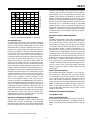
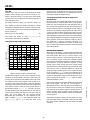
Figure 8. Beauty Video at 1 Bit per Pixel
The Raw2avi program can be used to measure the performance of the Bin Width Calculator. While doing its
primary job of converting raw ADV601 video into videofor-windows.avi files, the program finds the size of every field in the compressed video (.601) file. Raw2avi
records the field number, the field size, the compression
ratio and the number of bits per pixel of each field in a
side disk file named vid_siz.dat. The file is in ASCII,
and the following plot was generated from the side file
using a spread sheet. The target bit rate was 1 bit per
pixel. The input video was the Analog Devices
Beauty.601 file (distributed on the Videolab kit CDROM). Variable loop_gain was 8 (800 Hex after scaling). Int_gain and dir_gain were zero. Each scene
The program might compute the 42 differences between
this sum-of-squares and the last sum-of-squares. It
should then square or absolute value the 42 differences
(to prevent plus and minus differences from canceling
each other) and sum them to obtain a single measure of
image “change.” If this number is then divided by the
sum of all 42 bin width registers is will be normalized in
a useful fashion.
The present program changes the bin widths on every
field. The video might look better if field one and field
two were always quantized with the same bin width
numbers.
–8–
PRINTED IN U.S.A.
Recip_bw[i] = 1 / bin width[i]
E3170–.5–2/98
change causes an abrupt bit rate change. The narrow
spikes are only one field wide, corresponding to the one
field delay around the feedback loop.
curve.dsp
Module curve.dsp has a pair of 42 element bin width
register curves (arrays max and min) stored as constants in program memory. For each of the 42 bin width
registers curve.dsp computes the value from Equation 2
in the DO interp loop.