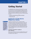
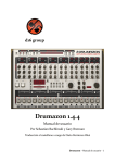
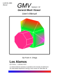
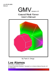
1
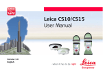
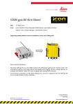
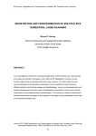
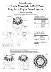
CloudWor x 3.0 Basi c and Pro for AutoCAD CloudWorx 3.0 Tutorial Cyclone CloudWorx 3.0 Basic & Pro for AutoCAD About CloudWorx 3.0 CAD systems usually have performance limitations when it comes to loading large datasets such as the millions of points typical in a scan cloud. When trying to import datasets like these, the CAD program often experiences severe performance problems and might even stall completely. Cyclone CloudWorx 3.0 for AutoCAD overcomes this limitation avoiding the direct import of the data but using Cyclone technology as the engine to efficiently manage and render point clouds within the AutoCAD environment. This enables working with point clouds within AutoCAD without impacting the performance of the CAD program. CloudWorx 3.0 for AutoCAD offers an enhanced suite of functions to better view and navigate through the point clouds. This tutorial gives an overview of the functionality available in both the Basic and Pro modules of Cyclone CloudWorx 3.0. The first section describes functonality available in CloudWorx Basic such as tools for clipping point clouds, region hiding, and creating basic deliverables. The second chapter covers additional functionality available in CloudWorx Pro. This document discusses a sample Survey/Architecture application and assumes that you are familiar with CAD. Objectives At the end of this lesson, you will learn how to: • • • • • • Load point clouds into AutoCAD Hide points using Hide Regions and manage these functions accordingly. Restore cutplanes saved in the database and create new additional slices. Bring the pointcloud on top of an existing drawing to verify a deliverable Use Fit Section tool for best fitting polylines into the point cloud Fit patch tool Page 1 of 29 Cyclone CloudWorx 3.0 Basic & Pro for AutoCAD Tutorial Copyright © 2004 Leica Geosystems HDS, Inc. All Rights Reserved Rev June16, 2004 RA CloudWor x 3.0 Basi c and Pro for AutoCAD CloudWorx 3.0 Tutorial Outline of Topics Covered This lesson includes the following topics: Section I – CloudWorx Basic 1. Introduction 2. Initialization 2.1 Starting up the ACAD drawing environment 2.2 Configuring a database 2.3 Loading the ModelSpace View 3. Hiding point cloud data 3.1 Hide Regions 3.2 Hide Region Manager 4. Clipping point cloud data 4.1 Sections Views and Slices 4.2 Cutplane Manager 5. Verifying deliverables Section II – CloudWorx Pro 6. Introduction to CloudWorx Pro 6.1 Best Fit Section 6.2 Fit Patch 6.3 Limit box manager 7. Creating basic deliverables with CloudWorx 3.0 Page 2 of 29 Cyclone CloudWorx 3.0 Basic & Pro for AutoCAD Tutorial Copyright © 2004 Leica Geosystems HDS, Inc. All Rights Reserved Rev June16, 2004 RA CloudWor x 3.0 Basi c and Pro for AutoCAD CloudWorx 3.0 Tutorial Section I 1 Introduction in CloudWorx Basic About CloudWorx and final goal This chapter describes the functionality offered in CloudWorx Basic 3.0. You will use CloudWorx tools to navigate through the clouds of points and verify existing deliverables. / CloudWorx commands can be given through: • CloudWorx menu • CloudWorx toolbars • AutoCAD command line This tutorial makes use of the CloudWorx menus and icons. Please refer to the CloudWorx 3.0 User’s Manual for the key-in commands. / The database used in this tutorial has been registered to a known coordinate system, thus ensuring the correct mapping in AutoCAD.If data you receive does not seem to be aligned correctly, please contact your service provider. Database and Files used with this Tutorial You will be working with the database House.imp and the AutoCAD drawing House.dwg with this tutorial. Page 3 of 29 Cyclone CloudWorx 3.0 Basic & Pro for AutoCAD Tutorial Copyright © 2004 Leica Geosystems HDS, Inc. All Rights Reserved Rev June16, 2004 RA CloudWor x 3.0 Basi c and Pro for AutoCAD CloudWorx 3.0 Tutorial 2 Initialization 2.1 Starting up the AutoCAD environment Starting up AutoCAD 1. Open the file House.dwg delivered with this tutorial 2. Notice the additional menu CloudWorx in your menu bar. Also, the CloudWorx tool bar is docked on the side of your working environment. These will be using in the tutorial. fig 3.0.1 2.2 Configure a database within AutoCAD Configuring a database A Cyclone database exists as a file name with an .imp extension. Follow the next steps to configure the database: House.imp. This establishes a connection between the database on the hard drive and the Cyclone engine, which serves the point clouds within the AutoCAD environment. / For Cyclone users (or Cyclone-VIEWER), these steps can also be done within the Cyclone application. 1. Save the file House.imp to your hard drive, e.g. under C:\Program Files\Cyra Technologies\Cyclone\Databases. / Ensure that the House.imp file is not Read Only by checking the file properties. Page 4 of 29 Cyclone CloudWorx 3.0 Basic & Pro for AutoCAD Tutorial Copyright © 2004 Leica Geosystems HDS, Inc. All Rights Reserved Rev June16, 2004 RA CloudWor x 3.0 Basi c and Pro for AutoCAD CloudWorx 3.0 Tutorial 2. In AutoCAD, select CloudWorxConfigure Databases… 3. Expand the Servers folder and highlight the existing server (by default it is your computer). 4. Click the Databases… button in the Configure Databases dialog. fig 2.3.0 5. Click the Add… button in the Configure Databases on Server Name dialog. 6. Select the “…” button next to the Database Filename field to browse to the provided database file: House.imp 7. Press Open when the file House.imp file has been located and selected. 8. Click OK in the Add Database dialog. fig 2.2.2 9. Select Close in the Configure Databases on Server Name dialog. 10. Click Close in the Configure Databases dialog. Page 5 of 29 Cyclone CloudWorx 3.0 Basic & Pro for AutoCAD Tutorial Copyright © 2004 Leica Geosystems HDS, Inc. All Rights Reserved Rev June16, 2004 RA CloudWor x 3.0 Basi c and Pro for AutoCAD CloudWorx 3.0 Tutorial fig 2.2.3 The database is now connected to the Cyclone engine and ready to be used in CloudWorx. / This operation has to be performed only once, as the database will not be automatically disconnected from the Cyclone engine if you shut down AutoCAD. To disconnect a specific database highlight it and use the Remove command in the Configure Databases on [computer name] dialog. 2.3 Loading a ModelSpace View in AutoCAD Loading a ModelSpace View Once a Cyclone database is connected, the point cloud data is ready to be loaded in AutoCAD. This is done by opening a ModelSpace View of this database. 1. Select CloudWorxOpen ModelSpace View… 2. In the Open ModelSpace View dialog, click the “…” button. fig 2.3.1 Page 6 of 29 Cyclone CloudWorx 3.0 Basic & Pro for AutoCAD Tutorial Copyright © 2004 Leica Geosystems HDS, Inc. All Rights Reserved Rev June16, 2004 RA CloudWor x 3.0 Basi c and Pro for AutoCAD CloudWorx 3.0 Tutorial 3. In the Select ModelSpace View dialog, browse down the Cyclone hierarchy by clicking the plus signs next to the appropriate objects. The path for the desired ModelSpace View is: House/ SanRamon/ ScanWorld (Registration)/ ModelSpaces/ ModelSpace1/ ModelSpace View 1. Highlight the “ModelSpace View 1” and click Open. fig 2.3.2 4. In the Open ModelSpace View dialog, set the AutoCAD units to meters. fig 2.3.3 / Data is stored in the Cyclone database in meters. If your AutoCAD working units is not meter, select the appropriate unit in the Open ModelSpace View dialog to scale the data match your working units. / The Default Coordinate System within Cyclone is typically used to load the point clouds in AutoCAD’s World Coordinate System (WCS). Saved User Coordinate Systems (UCS) the Cyclone ModelSpace View can also be selected from the Coordinate Systems drop down menu and used. Cyclone’s are mapped to the AutoCAD UCS named with the prefix “~”. 5. Click OK in the Open ModelSpace View dialog to load the points. The command line will update during this process, displaying the number of points being loaded (Fig 2.3.4). Ø Each Model Space View remembers the settings and overrides the way the clouds of points were viewed the last time. Any view changes related to the launched ModelSpace View will not be stored in the database. Page 7 of 29 Cyclone CloudWorx 3.0 Basic & Pro for AutoCAD Tutorial Copyright © 2004 Leica Geosystems HDS, Inc. All Rights Reserved Rev June16, 2004 RA CloudWor x 3.0 Basi c and Pro for AutoCAD CloudWorx 3.0 Tutorial 6. Zoom and see extents of the entire scene. 7. Zoom into the yellow area in the center of the scans. This data represents the house, which we will work with. Move and rotate around the data to get an understanding of the scene. / Use the command CloudWorx Regenerate Point Clouds to bring more detail into view after zooming in. Regenerate point clouds (CWREGEN) loads any additional point cloud information available in the ModelSpace View. Remember that performance will slow down with increasing the number of points loaded, especially when rotating the scene. fig 2.3.4 3 Hiding Point Cloud Data Hiding Point Clouds You can temporarily hide extraneous data from your view. Multiple Hide Regions can be used and are managed in the Hide Region Manager / The point clouds are Read Only in AutoCAD and none of the following functions delete any data. The points are simply temporarily hidden from view. Page 8 of 29 Cyclone CloudWorx 3.0 Basic & Pro for AutoCAD Tutorial Copyright © 2004 Leica Geosystems HDS, Inc. All Rights Reserved Rev June16, 2004 RA CloudWor x 3.0 Basi c and Pro for AutoCAD CloudWorx 3.0 Tutorial 3.1 Hide Regions Hide Regions Hide Regions allows you to hide points inside or outside a fence. Use these commands to hide extraneous data captured on the trees around the house. 1. View your scene in Top View. Zoom In so that the building nearly fills your view. 2. Activate the command CloudWorxHide/ Restore Points Hide Points Outside Fence . 3. Enter R in the AutoCAD command line to specify a Rectangular fence. / You can also use a Circular [C] or Polygonal [P] fence 4. Draw a fence around the outside of the building, excluding any data of the tree. 5. The extraneous data is now hidden from view, and your view should resemble Fig. 3.1.1 fig 3.1.1 6. Hide the points inside the building, this time using the command Hide Points Inside Fence. 7. Your final view should look like Fig 3.1.2 Page 9 of 29 Cyclone CloudWorx 3.0 Basic & Pro for AutoCAD Tutorial Copyright © 2004 Leica Geosystems HDS, Inc. All Rights Reserved Rev June16, 2004 RA CloudWor x 3.0 Basi c and Pro for AutoCAD CloudWorx 3.0 Tutorial fig 3.1.2 8. Orbit around in the scene to view the results. The 2D fence is projected all the way through your clouds and hides everything inside/outside of this projection. / CloudWorx’ Hide Inside, Hide Outside, Restore Inside and Restore Outside commands all work in the same way, based on a user defined fence. / To display all hidden points again, use the command Delete All. 3.2 Hide Regions Manager Hide Regions Manager The Hide Region Manager allows the user to enable/disable or delete any hidden regions. / Any operation executed here will be stored and is accessible in further work sessions. 1. Activate the dialog through CloudWorxHide/Restore Point CloudHide Regions Manager 2. Both Hide Regions settings are displayed in the Hide Regions Manager dialog with the active View State. Page 10 of 29 Cyclone CloudWorx 3.0 Basic & Pro for AutoCAD Tutorial Copyright © 2004 Leica Geosystems HDS, Inc. All Rights Reserved Rev June16, 2004 RA CloudWor x 3.0 Basi c and Pro for AutoCAD CloudWorx 3.0 Tutorial fig 3.3.0 3. Toggle the State of the Hide Operation and click OK to examine the results. 4. To proceed with this tutorial, open the Hide Regions Manager and set the State of the first Hide Regions Operation to ON and that of the second Hide Regions Operation to OFF. / Remove or Delete a Hide Regions operation by highlighting ) it in the Hide Regions Manager and clicking Delete. All Hide Regions Operations can be deleted at once using the Clear All command. Ø Another more general means of controlling the display of point clouds is done by selecting CloudWorxSnap/Visibility. Here, you can to hide all of the point clouds at once. fig 3.2.2 4 Clipping Point Cloud Data In addition to hiding point clouds by fence regions, you can also define slices through the point cloud data for viewing. This feature enables you to view sections or slices of the point clouds. Clipping operations are managed in the Cutplane Manager. / Like with the hide region commands, point cloud data is not actually deleted, only temporarily hidden from view. 4.1 Section Views and Slices Page 11 of 29 Cyclone CloudWorx 3.0 Basic & Pro for AutoCAD Tutorial Copyright © 2004 Leica Geosystems HDS, Inc. All Rights Reserved Rev June16, 2004 RA CloudWor x 3.0 Basi c and Pro for AutoCAD CloudWorx 3.0 Tutorial Section View The Clip Points to Section command allows you to define a plane in 3D and then only display points to one side of this view. 11. Set up an extra viewport so that you are viewing your scene in Top and in Front views. Make the Front view the active viewport. 12. Select CloudWorxClip Point CloudSection ViewY axis positive 13. Define the section cut just below the roof of the main building. 4. Your result should be similar to Fig 4.1.1. In this case defining a section view allows you to look inside the building without the roof data obstructing your view. fig 4.1.1 5. Define a new section view along the X-axis. Notice that upon this second section replaces the first one. 6. Restore all the points, using the command Turn Off Section Clipping. / Whereas multiple hiding functions can be active at the same time, only one clipping function can be activated at one time. Page 12 of 29 Cyclone CloudWorx 3.0 Basic & Pro for AutoCAD Tutorial Copyright © 2004 Leica Geosystems HDS, Inc. All Rights Reserved Rev June16, 2004 RA CloudWor x 3.0 Basi c and Pro for AutoCAD CloudWorx 3.0 Tutorial Slice The Clip Points To Slice command allows you to define two parallel planes in 3D and hide the points outside these planes, resulting in a controlled cross-section view of the point cloud. Use these commands to create a slice representing the groundplan of the building. 1. Make the Front View the active one. 2. Select CloudWorxClip Point CloudSlicey axis. As you invoke this command and move over the front view, a temporary line is attached to your curser, indicating your first clipping plane. 3. Place this line just above the ground level and accept. 4. As this plane is locked in place, another line is now attached to your curser, representing the second cutplane. Place this at a small interval above the first plane and accept. fig 4.1.2 5. Point clouds outside this defined slice are clipped from view. Your view should ressemble Fig 4.1.3, thus creating a cross section representing the ground plan of the building. Page 13 of 29 Cyclone CloudWorx 3.0 Basic & Pro for AutoCAD Tutorial Copyright © 2004 Leica Geosystems HDS, Inc. All Rights Reserved Rev June16, 2004 RA CloudWor x 3.0 Basi c and Pro for AutoCAD CloudWorx 3.0 Tutorial fig 4.1.3 6. Use the Slice Forward positive direction of the axis. command to move the slice up along the / The slice is moved incrementally by a distance equal to the thickness of the slice. 7. Restore all the points by selecting CloudWorxClip Point Cloud Slice Off . 4.2 Cutplane Manager Cutplane Manager Until now one active cutplane was used with each operation modifying the active cutplane. Multiple cutplanes can be created, managed and used via the Cutplane Manager. The Cutplane Manager enables you: Page 14 of 29 Cyclone CloudWorx 3.0 Basic & Pro for AutoCAD Tutorial Copyright © 2004 Leica Geosystems HDS, Inc. All Rights Reserved Rev June16, 2004 RA CloudWor x 3.0 Basi c and Pro for AutoCAD CloudWorx 3.0 Tutorial Ø Restore and view cutplanes, which have been set up and saved in Cyclone or Cloudworx Pro user. Ø Define and save new cutplanes for the working session. Notice that when using CloudWorx Basic these are only stored temporarily and will be lost upon closing the AutoCAD session. / CloudWorx Pro allows the user to save additional cutplanes since they are saved to the ModelSpace Restoring Cutplanes Restoring Saved Cutplanes 1. Activate the Manager through CloudWorxClip Point Cloud Cutplane Manager. fig 4.3.0 2. Three cutplanes have been pre-defined here, representing slices of elevations from different sides of the building, as well as a horizontal slice resulting in a footprint of the building. 3. Notice that the Cutplane “Horizontal slice” is displayed in bold. This indicates that it is set as the active cutplane. 4. Make the “Front Facade” Cutplane Current by highlighting it and selecting Set Current. 5. Toggle ON the visibility of the “Front Facade” cutplane and press OK. 6. Your display should now look like Fig 4.2.2. Page 15 of 29 Cyclone CloudWorx 3.0 Basic & Pro for AutoCAD Tutorial Copyright © 2004 Leica Geosystems HDS, Inc. All Rights Reserved Rev June16, 2004 RA CloudWor x 3.0 Basi c and Pro for AutoCAD CloudWorx 3.0 Tutorial fig 4.2.2 6. Restore all the point clouds by toggling OFF the “Show” column. 7. Switch to another cutplane by executing the following commands: a) Open the Cutplane Manager. b) Select the desired cutplane. c) Press Set Current, to make this cutplane Active. d) Toggle ON the visible by checking the “Show” column. e) Press OK to close the Cutplane Manager and update the view. 8. Switch between various cutplanes to view the saved cutplanes of different viewpoints. • Page 16 of 29 Cyclone CloudWorx 3.0 Basic & Pro for AutoCAD Tutorial Copyright © 2004 Leica Geosystems HDS, Inc. All Rights Reserved Rev June16, 2004 RA CloudWor x 3.0 Basi c and Pro for AutoCAD CloudWorx 3.0 Tutorial Creating Cutplanes Creating Additional Cutplanes 1. Within the Cutplane Manager, select the New button to create a new slice. 2. Rename it by clicking twice on the cutplane name. 3. Make the new cutplane current by highlighting it and then clicking the Set Current button. 4. Toggle OFF the visibility of the cutplane. 5. Click OK 6. Define the slice or section view desired. 7. The cutplane is updated in real-time. / The thickness of a slice can be changed by typing in a different value in the thickness column. / The type of the cutplane can be toggled between slice and section view by / / clicking into the type field. For section views, highlighting the cutplane and selecting Flip Direction switches the displayed part of the point cloud to the other side of the plane Any additional cutplanes defined in CloudWorx Basic are stored temporarily and are lost upon closing the work session. • 4.3 Finalizing Tracing, dimensioning, point info, After all clipping operations have been done, we are ready to create the 2D plan of the house. The point of clouds can give us access to rich, accurate data that serves as a starting point for many design activities. All CAD drafting tools can be accessed directly from a CloudWorx session, so you can draw polylines along the features of interest, acquire the 3D position of any point, get dimensions, etc. To create the 2D plan : 1. Look at your scene in Top view 2. In the Cutplane Manager, set “Horizontal slice” as the current cutplane and make it visible. 3. Using the snapping functions, draw polylines describing the boundary of the building. 4. Using the CAD dimensioning tool, place dimensions necessary for the architectural plan of the building 5. You can obtain the 3D point information/elevation of any point by selecting CloudWorxPoint Cloud Information Page 17 of 29 Cyclone CloudWorx 3.0 Basic & Pro for AutoCAD Tutorial Copyright © 2004 Leica Geosystems HDS, Inc. All Rights Reserved Rev June16, 2004 RA CloudWor x 3.0 Basi c and Pro for AutoCAD CloudWorx 3.0 Tutorial fig 5.1 Fig. 5.1 shows sample deliverable as 2D plan of the building Page 18 of 29 Cyclone CloudWorx 3.0 Basic & Pro for AutoCAD Tutorial Copyright © 2004 Leica Geosystems HDS, Inc. All Rights Reserved Rev June16, 2004 RA CloudWor x 3.0 Basi c and Pro for AutoCAD CloudWorx 3.0 Tutorial Section II 5 Introduction to CloudWorx Pro About CloudWorx Pro This section describes functionalities offered in CloudWorx Pro, as well as differences between CloudWorx Basic and CloudWorx Pro. In addition to the features that have been introduced with CloudWorx Basic in the previous section, CloudWorx Pro includes additional tools: fitting and connecting pipes, fitting a patch, fitting line drawings to point cloud data, interference checking, point cloud color mapping, managing point clouds using the ScanWorld Explorer and using the limit box manger. This exercise introduces the features Best Fit Section and Fitting a patch, which are used in the Survey/Architecture workflow. Fig. 6.1 Page 19 of 29 Cyclone CloudWorx 3.0 Basic & Pro for AutoCAD Tutorial Copyright © 2004 Leica Geosystems HDS, Inc. All Rights Reserved Rev June16, 2004 RA CloudWor x 3.0 Basi c and Pro for AutoCAD CloudWorx 3.0 Tutorial 5.1 Best Fit Section Best Fit Section The Best Fit Section tool adjusts lines, arcs, polylines or groups of line objects to best fit the point cloud data. To execute this command, you must have an active slice of point cloud data. All line objects will be projected to the center plane of the slice after fitting is performed. It is recommended that you work on a view that is aligned to the slice plane. To fit polylines: 1. 2. Activate the Manager through CloudWorxClip Point Cloud Cutplane Manager. Select the “Right Facade” cutplane by highlighting it and press Set Current, to make this cutplane active. / The Clipping operations in CloudWorx Pro update the ModelSpace in the Cyclone Database when the DWG file is saved. For users of Cyclone, the Cutplane Manager and Limit Box will update to reflect any changes made using CloudWorx Pro. 3. 4. View the point cloud from the Right View Draw a polyline and arc approximately around one of the windows (fig. 6.1.1) Fig. 6.1.1 5. Select CloudWorxFit Point CloudSection Page 20 of 29 Cyclone CloudWorx 3.0 Basic & Pro for AutoCAD Tutorial Copyright © 2004 Leica Geosystems HDS, Inc. All Rights Reserved Rev June16, 2004 RA CloudWor x 3.0 Basi c and Pro for AutoCAD CloudWorx 3.0 Tutorial Best Fit Section dialog Fig. 6.1.2 Items to specify in this dialog: — Lock Shape (Rigid): if checked, the shape is locked and adjusted as a rigid object Grid Locks : — Snap and Grid: if checked, the directions of line segments will be aligned to the SnapX spacing and SnapY spacing of the current AutoCAD Snap and Grid settings. The Angle, X base and Y base must be set to zero. The current UCS has to be aligned to the slice plane. — Polar Tracking: when checked, the segments of the sections will be adjusted to the Increment Angle of the current AutoCAD Polar Tracking settings. The current UCS has to be aligned to the slice plane. Tolerances: — — — — Intersection Tolerance: Will detect the connectivity of end points of open polylines/arcs and force them to close if within the specified tolerance. / Using big tolerance may generate unexpected topological change. Perpendic. Tolerance: If not zero, will adjust the line segments to perpendicular or parallel when the error falls into this tolerance. For example if the tolerance is 10 degree, this means that when the line segments form an angle within 80°-100° (90°±10°) or 10° (0°±10°), the fitted lines will be forced to be perpendicular or parallel. Max. point Distance: This value determines the maximum distance that the curve can vary to fit into the point cloud. In other words during the fitting process, the lines/arcs will not be adjusted more than this value. Point Accuracy: Defines the quality of the cloud points, for Cyrax scanner it is 6mm 6. Check the Polar Tracking (inc = 90 deg) to make the result polyline with perpendicular segments. 7. Click on the Pick button and select the polyline 8. Press Enter to execute the command 9. The resulting polyline will be with perpendicular segments and the best fit to the point cloud in this section. Here is an example of final deliverable using the Best Fit Section tool (Fig 6.1.2) Page 21 of 29 Cyclone CloudWorx 3.0 Basic & Pro for AutoCAD Tutorial Copyright © 2004 Leica Geosystems HDS, Inc. All Rights Reserved Rev June16, 2004 RA CloudWor x 3.0 Basi c and Pro for AutoCAD CloudWorx 3.0 Tutorial Fig. 6.1.2 5.2 Fit Patch Fit Patch You can fit a patch to a point cloud or multiple clouds based on a pick point or fence, respectively. This can be used to generate a 3D model of the building. The result is 3DFACE or PolyFaceMesh depending on the complexity of the result. To fit a patch: 6. 7. View the point cloud from the Right View and make sure the Right Facade cutplane is still active Select CloudWorxFit Point CloudPatch Fig. 6.3.0 Page 22 of 29 Cyclone CloudWorx 3.0 Basic & Pro for AutoCAD Tutorial Copyright © 2004 Leica Geosystems HDS, Inc. All Rights Reserved Rev June16, 2004 RA CloudWor x 3.0 Basi c and Pro for AutoCAD CloudWorx 3.0 Tutorial / The default Maximum RMS Error is 6 mm. Leave this value at its default setting unless you are working with point clouds with a different level of sampling error. 8. The following options exist for the resulting patch – Convex Hull or Minimum Rectangle. For the plot we are making, select Minimum Rectangle. 9. Fit a patch based on a pick point. Object Snap must be enabled with the “Node” type toggled ON. This will enable snapping to a point in the cloud. Click the Pick>> button. 10. Pick a point from the wall to serve as the “seed point”. The algorithm determines the plane of the wall by using the neighbouring points and ignores the points which do not fit the patch. 11. The result is a 3d face representing the east wall of the building Fig. 6.2.2 Page 23 of 29 Cyclone CloudWorx 3.0 Basic & Pro for AutoCAD Tutorial Copyright © 2004 Leica Geosystems HDS, Inc. All Rights Reserved Rev June16, 2004 RA CloudWor x 3.0 Basi c and Pro for AutoCAD CloudWorx 3.0 Tutorial Now, fit a patch based on a fence: 1. 2. 3. 4. 5. Activate the Manager through CloudWorxClip Point CloudCutplane Manager Select the “Front Facade” cutplane by highlighting it and press Set Current, to make this cutplane the active one. View the point cloud from the Front view Select CloudWorxFit Point Cloud Patch In the Fit Patch dialog click Fence>> The command line prompts you to select the type of fence to create. We will create a polygonal fence. 6. Type P to make a polygonal fence, then press Enter 7. Define the polygonal fence’s shape by encompassing all of the points that will be used in the fit. 8. When finished making the fence, press Enter. The patch will be fit based on the points that lie inside the fence. / When fitting a patch using the “Fence>>” option, ALL points encompassed by the fence are used to create the patch. Be careful not to include unwanted points inside the fence! / Note that the error of the fit results appear in the command line after a successful fit. 5.3 Limit box manager and creating Limit boxes Working with Limit Boxes Limit boxes can now be created directly in AutoCAD or be brought over from a Cyclone ModelSpace. A limit box manager is used to manage, create, edit and controls which limit box is active. Start by creating a limit box. Creating a limit Box in AutoCAD 1. Start by viewing the house from an isometric view as shown in figure 6.3.1. Use the view tool bar and choose the view highlighted by the arrow. You may have to zoom in to get the house to fill up the screen. Page 24 of 29 Cyclone CloudWorx 3.0 Basic & Pro for AutoCAD Tutorial Copyright © 2004 Leica Geosystems HDS, Inc. All Rights Reserved Rev June16, 2004 RA CloudWor x 3.0 Basi c and Pro for AutoCAD CloudWorx 3.0 Tutorial Creating a Limit Box Figure 6.3.1 2. Begin by creating a limit box around part of the house. Go to the menu command CloudWorx ?Clip Point Cloud ?Limit Box. As shown in Figure 6.3.2. Figure 6.3.2 3. Using the snapping function, select a point representing one corner of the desired 3D limit box. Page 25 of 29 Cyclone CloudWorx 3.0 Basic & Pro for AutoCAD Tutorial Copyright © 2004 Leica Geosystems HDS, Inc. All Rights Reserved Rev June16, 2004 RA CloudWor x 3.0 Basi c and Pro for AutoCAD CloudWorx 3.0 Tutorial Creating a limit box 4. Position the crosshair at the point representing the opposite corner of the desired limit box and click (or enter coordinates for the second corner at the command line and press ENTER). The resulting rectangle is projected onto the work plane. See Figure 6.3.5 Below First pick Second pick Work plane Figure 6.3.5 5. Position the crosshair and select a point to determine the height of the box. If you select the Height keyword, you can also enter the value of the height. Extents of limit box Figure 6.3.6 Page 26 of 29 Cyclone CloudWorx 3.0 Basic & Pro for AutoCAD Tutorial Copyright © 2004 Leica Geosystems HDS, Inc. All Rights Reserved Rev June16, 2004 RA CloudWor x 3.0 Basi c and Pro for AutoCAD CloudWorx 3.0 Tutorial Clipped Point Cloud with limit box 6. Points outside the boundaries of the box are hidden from view. See figure 6.3.7 below. Ø If all points are hidden after applying the limit box, it is likely that the limit box is defined in an incorrect position. In this case, turn the limit box OFF and try again. Figure 6.3.7 7. Follow the steps below to turn off and create additional limit boxes. 5.4 Working with the Limit Box Manager Using the Limit box manager 1. Open the limit box manger from the command Cloudworx ?Clip Point Cloud ?Limit Box Manager. You will see a dialog come up. The new limit box shown is the one you just created. Try turning the limit box you just created off by un-checking the Enable Limit box in the lower right of the dialog. Click OK and the limit box will turn off. See figure 6.3.8 below. Figure 6.3.8 Page 27 of 29 Cyclone CloudWorx 3.0 Basic & Pro for AutoCAD Tutorial Copyright © 2004 Leica Geosystems HDS, Inc. All Rights Reserved Rev June16, 2004 RA CloudWor x 3.0 Basi c and Pro for AutoCAD CloudWorx 3.0 Tutorial Notes on Limit Box Manager Functionality Displays the name of the Limit Box. Type topic text here. Displays limit box dimensions. Indicates whether or not the limit box is aligned with the current user coordinate system axes. New: Creates a new limit box that is a copy of the currently selected limit box. The new limit box is automatically identified as a copy of the original limit box. Delete: Deletes the selected limit box. Set Sets the selected Limit Box as the active Limit Box. Name: X, Y, Z: W, H, D: Align: Current: Info: Displays the parameters of the selected limit box. Enable Select this check box to enable the current limit box. Limitbox: Show Select this check box to display limit boxes or clear this check box to Limit hide limit boxes. Box: Show All:Select this check box to display all limit boxes or clear this check box to display only activated limit boxes. When selected (and all limit boxes are displayed), the active limit box is highlighted with thick lines and the selected limit box is displayed with dashed lines. Page 28 of 29 Cyclone CloudWorx 3.0 Basic & Pro for AutoCAD Tutorial Copyright © 2004 Leica Geosystems HDS, Inc. All Rights Reserved Rev June16, 2004 RA CloudWor x 3.0 Basi c and Pro for AutoCAD CloudWorx 3.0 Tutorial 7. Creating deliverables with CloudWorx 3.0 Final deliverables When you save your AutoCAD file, changes made to the point clouds (ModeSpace View) during the session are saved to the database. Each ModelSpace View stores the new settings the way the clouds of points were viewed during the last session. Depending on the final deliverable, the user can save the final DWG file with connection to the database/point clouds (deliver the DWG file and Cyclone database), or save only AutoCAD objects without reference to point clouds (deliver only the DWG file): 1. Providing DWG with database to a customer who has CloudWorx: When delivering a DWG file such as the one created in this tutorial with a Cyclone database, the end user will need to configure the database on their local machine. When loading the DWG file, CloudWorx looks for the associated name on the local Cyclone server. 2. Providing DWG only to a customer who does not have CloudWorx: / When delivering a DWG file created using CloudWorx to an end user without CloudWorx, the user should perform a CloudWorx “purge” to remove all references to CloudWorx objects that are stored in the DWG when the DWG file is saved. To do this, first you need to select CloudWorxClose ModelSpace View to disconnect from the current ModelSpave View, and then execute CloudWorxPurge command. Save the DWG file (save it as a different name to keep the CloudWorx data in the non-purged DWG). Doing this ensures that the end user who may not have CloudWorx installed does not receive a Proxy Dialog upon opening the DWG. Page 29 of 29 Cyclone CloudWorx 3.0 Basic & Pro for AutoCAD Tutorial Copyright © 2004 Leica Geosystems HDS, Inc. All Rights Reserved Rev June16, 2004 RA