1
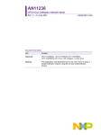
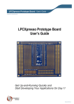
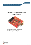
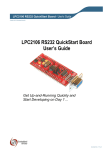
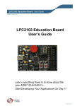
LPC11U35 QuickStart Board - User’s Guide Copyright 2012 © Embedded Artists AB LPC11U35 QuickStart Board User’s Guide Get Up-and-Running Quickly and Start Developing Your Applications On Day 1! EA2-USG-1205 Rev A LPC11U35 QuickStart Board - User’s Guide Page 2 Embedded Artists AB Davidshallsgatan 16 SE-211 45 Malmö Sweden [email protected] http://www.EmbeddedArtists.com Copyright 2010-2012 © Embedded Artists AB. All rights reserved. No part of this publication may be reproduced, transmitted, transcribed, stored in a retrieval system, or translated into any language or computer language, in any form or by any means, electronic, mechanical, magnetic, optical, chemical, manual or otherwise, without the prior written permission of Embedded Artists AB. Disclaimer Embedded Artists AB makes no representation or warranties with respect to the contents hereof and specifically disclaim any implied warranties or merchantability or fitness for any particular purpose. Information in this publication is subject to change without notice and does not represent a commitment on the part of Embedded Artists AB. Feedback We appreciate any feedback you may have for improvements on this document. Please send your comments to [email protected]. Trademarks All brand and product names mentioned herein are trademarks, services marks, registered trademarks, or registered service marks of their respective owners and should be treated as such. Copyright 2012 © Embedded Artists AB LPC11U35 QuickStart Board - User’s Guide Page 3 Table of Contents 1 Document Revision History 4 2 Introduction 5 2.1 Features 5 2.2 ESD and Handling Precaution 5 2.3 General Handling Care 6 2.4 Code Read Protection 6 2.5 CE Assessment 6 2.6 Other Products from Embedded Artists 6 2.6.1 Design and Production Services 6 2.6.2 OEM / Education / QuickStart Boards and Kits 7 3 Schematic 8 3.1 Powering 8 3.2 LPC11U35 MCU 8 3.3 Reset Generation 8 3.4 LED on PIO0_7 8 3.5 USB Interface 8 3.6 Bootload Enable Push-button 9 3.7 SWD interface 9 3.8 Expansion Connectors 10 3.9 Usage of MCU Pins 11 4 Physical Design 4.1 Main Components 13 4.2 Mechanical Dimensions 14 5 Getting Started 15 5.1 SWD Interface 15 5.2 Activate LPC11U35 ISP Mode 16 5.2.1 Copyright 2012 © Embedded Artists AB 13 USB-ISP Mode 16 6 Further Information 20 LPC11U35 QuickStart Board - User’s Guide Page 4 1 Document Revision History Revision Date Description PA1 2012-06-18 First draft. Copyright 2012 © Embedded Artists AB LPC11U35 QuickStart Board - User’s Guide Page 5 2 Introduction Thank you for buying Embedded Artists’ LPC11U35 QuickStart Board based on NXP’s LPC11U35 ARM Cortex-M0 microcontroller. This document is a User’s Guide that describes the LPC11U35 QuickStart Board hardware design. 2.1 Features Embedded Artists’ LPC11U35 QuickStart Board with NXP’s LPC11U35 microcontroller lets you get upand-running quickly. The small sized board offers many features that ease your learning curve and speed up your program development. The features of the LPC11U35 QuickStart Board are: NXP's LPC11U35 ARM Cortex-M0 microcontroller in 33-pin HVQFN package, with 10 KByte internal SRAM, 64 Kbyte internal FLASH and 4Kbyte internal EEPROM. 12.0000 MHz crystal for maximum execution speed and standard serial bit rates, including USB requirements. The LPC11U35 runs at frequencies up to 50 MHz. On-board USB Device interface Mini-B USB connector on-board USB connect circuit with LED signaling Proper ESD protection All LPC11U35 pins available on expansion connector (dual 15 pos, 100 mil/2.54 mm pitch rows, 700 mil/17.78 mm apart). Flexible powering, with on-board 150mA 3.3V voltage regulator Can be powered from USB connector or an external +5V supply Onboard reset generation Reset push button Push button for enabling Bootloader mode of the LPC11U35 LED on pin PIO0_7 SWD/JTAG connector 2x5 pos, 50 mil/1.27 mm pitch, standard SWD/JTAG connector Compact size: 22 x 40 mm (22 x 41 mm incl. USB connector) 2.2 Expansion connectors has DIP30 structure, suitable for breadboard prototyping Four layer PCB design for best noise immunity ESD and Handling Precaution Please note that the LPC11U35 QuickStart Board come without any case/box and all components are exposed for finger touches – and therefore extra attention must be paid to ESD (Electro-Static Discharge) precaution. Make it a habit to always first touch the metal surface of the USB connectors for a few seconds with both hands before touching any other parts of the boards. That way, you will have the same electrical potential as the board and therefore minimize the risk for ESD damages. In general, touch as little as possible directly on the LPC11U35 QuickStart Board. The push buttons on the LPC11U35 QuickStart Board have grounded shield to minimize the effect of ESD. Copyright 2012 © Embedded Artists AB LPC11U35 QuickStart Board - User’s Guide Page 6 Note that Embedded Artists does not replace boards that have been damaged by ESD. 2.3 General Handling Care Handle the LPC11U35 QuickStart Board with care. The board is not mounted in a protective case/box and is not designed for rough physical handling. The USB connector can ware out after excessive use. The board is mainly designed for evaluation and prototyping use. 2.4 Code Read Protection The LPC11U35 has a Code Read Protection function (specifically CRP3, see LPC11U35 datasheet/user’s manual for details) that, if enabled, will make the LPC11U35 impossible to reprogram (unless the user program has implemented such functionality). Note that Embedded Artists does not replace boards where the LPC11U35 has CRP3 enabled. It’s the user’s responsibility to not invoke this mode by accident. 2.5 CE Assessment The LPC11U35 QuickStart Board is CE marked. See separate CE Declaration of Conformity document. The LPC11U35 QuickStart Board is a class B product. EMC emission test has been performed on the LPC11U35 QuickStart Board. The USB interface has been in use and also powered the device during the test. General expansion connectors where internal signals are made available have been left unconnected. Connecting other devices to the product via the general expansion connectors may alter EMC emission. It is the user’s responsibility to make sure EMC emission limits are not exceeded when connecting other devices to the general expansion connectors of the LPC11U35 QuickStart Board. Due to the nature of the LPC11U35 QuickStart Board – a prototype and evaluation board – fast transient immunity tests and conducted radio-frequency immunity tests have not been executed. Externally connected cables are assumed to be less than 3 meters. The general expansion connectors where internal signals are made available do not have any other ESD protection than from the chip themselves. Observe ESD precaution. Note that the LPC11U35 QuickStart Board can also be considered to be a component if integrated into another product. The CE mark on the LPC11U35 QuickStart Board cannot be extended to include the new (user created) product. It is the user’s responsibility to make sure EMC emission limits are not exceeded and CE mark the final product. 2.6 Other Products from Embedded Artists Embedded Artists have a broad range of LPC1000/2000/3000/4000 based boards that are very low cost and developed for prototyping / development as well as for OEM applications. Modifications for OEM applications can be done easily, even for modest production volumes. Contact Embedded Artists for further information about design and production services. 2.6.1 Design and Production Services Embedded Artists provide design services for custom designs, either completely new or modification to existing boards. Specific peripherals and I/O can be added easily to different designs, for example, communication interfaces, specific analog or digital I/O, and power supplies. Embedded Artists has a broad, and long, experience in designing industrial electronics in general and with NXP’s LPC1000/2000/3000/4000 microcontroller families in specific. Our competence also includes wireless and wired communication for embedded systems. For example IEEE802.11b/g (WLAN), Bluetooth™, ZigBee™, ISM RF, Ethernet, CAN, RS485, and Fieldbuses. Copyright 2012 © Embedded Artists AB LPC11U35 QuickStart Board - User’s Guide 2.6.2 Page 7 OEM / Education / QuickStart Boards and Kits Visit Embedded Artists’ home page, www.EmbeddedArtists.com, for information about other OEM / Education / QuickStart boards / kits or contact your local distributor. Copyright 2012 © Embedded Artists AB LPC11U35 QuickStart Board - User’s Guide Page 8 3 Schematic This chapter contains detailed information about the electrical and mechanical design of the LPC11U35 QuickStart Board. The schematic can be downloaded in pdf format from the support page, and is recommended to have printed out while reading this chapter. 3.1 Powering The board is powered either via the USB interface or from an external +5V supply. U2 is an on-board voltage regulator capable of creating a +3.3V voltage for the LPC11U35. It can deliver up to 150 mA. The LPC11U35 itself does not consume that much so there is at least 100mA available for external circuit use. If an external +5V supply is used, it shall be stable with less than 50mV noise. Input supply voltage should not exceed +5.5V since this is the maximum allowed voltage on the LPC11U35 VBUS pin. Technically it is possible to have higher voltage on the external supply since the VBUS pin is connected via a 2Kohm resistor. The input protection diodes on the VBUS pin will clamp the voltage to +5.5V. Under no circumstances should the input voltage exceed 16V, which is the maximum input voltage for the voltage regulator, U2. See the datasheet for details. 3.2 LPC11U35 MCU The microcontroller unit (MCU), U1, is the LPC11U35 from NXP. It contains a Cortex-M0 core that can operate at frequencies up to 50 MHz. Internal PLL:s can create the core clock of 48 MHz from the external 12.0000 MHz crystal. A USB clock reference of 48 MHz can also be created this way. The LPC11U35 contains a lot of different peripheral units. See the LPC11U35 User’s Manual [2] for details about the peripherals, clock and power control. 3.3 Reset Generation The reset generation is handled by a voltage supervisor chip, MIC6315-29D3U from Micrel. The reset signal will be held active (i.e., low) until the supply voltages, +3.3V, is within margins (above 2.93V). The reset duration is typically 200 mS (consult the MIC6315-29D3U datasheet for exact details). The output reset signal is open-drain so a pull-up resistor is needed (R15). There is a reset-LED that lights when reset is active. An external reset source can pull the reset signal low (with an open-collector/open-drain output). There is also a reset push-button (SW1) for manual triggering of a reset pulse. 3.4 LED on PIO0_7 Further, there is a LED connected to pin PIO0_7. A 2Kohm resistor limits the diode current to about 0.9mA. The LED will light when PIO0_7 is high. The PIO0_7 pin is a high-drive output capable of supplying up to 20 mA. See the datasheet for details. 3.5 USB Interface The LPC11U35 has an on-chip USB Device interface. This interface is supported on-board via a miniB USB connector, J3. There is also a USB connect functionality to connect a 1.5Kohm resistor to the USB-DP signal. This functionality also has LED indication. The board is typically powered via the USB interface. The USB interface is protected by ESD protection diode, D1. Note that if USB-ISP mode is activated, it is possible to download firmware into the LPC11U35 via the USB interface. Copyright 2012 © Embedded Artists AB LPC11U35 QuickStart Board - User’s Guide 3.6 Page 9 Bootload Enable Push-button The LPC11U35 sample the state of the PIO0_1 pin immediately after a reset. If the pin is low, the ISP mode is activated and further the pin PIO0_3 is sampled. If high, USB-ISP mode is activated and if low, UART-ISP mode is activated. Read the LPC11U35 User’s Manual [2] for details. The bootloader push-button, SW2, will pull pin PIO0_1 low via a 2Kohm resistor. The resistor minimizes the risk of damaging the PIO0_1 pin if it is operating as an output. Also, possible external drivers of the pin are protected via the 2Kohm resistor. Note that if an external source drives the signal strongly (i.e., with low impedance), the 2Kohm resistor will not be enough to pull Pin PIO0_1 low. To summarize the following pin states after reset are affecting the ISP mode: PIO0_1 PIO0_3 Mode after reset 1 N/A Execute code from flash memory 0 0 Enter UART-ISP mode 0 1 Enter USB-ISP mode 3.7 SWD interface There is a 10 pos (2x5 pos, 50 mil pitch) connector SWD interface for debugging and program download. This is a standard connector for the ARM Cortex-M0 processor. Copyright 2012 © Embedded Artists AB LPC11U35 QuickStart Board - User’s Guide 3.8 Page 10 Expansion Connectors There are two expansion connectors, J1 and J2. They both have 15 positions and are placed at the board edges. See Figure 2 on page 13 for details about J1 and J2 placement on the board. All programmable pins of the LPC11U35 are available on the expansion connectors; see the table below for details. On-board function LED SWCLK SWDIO Copyright 2012 © Embedded Artists AB LPC11U35 pin Exp. conn. DIL30 pin no DIL30 pin no Exp. conn. LPC11U35 On-board pin function GND J1-1 1 30 J2-1 GND VBUS-5V J1-2 2 29 J2-2 +3.3V PIO0_7 J1-3 3 28 J2-3 PIO0_6 PIO0_8 J1-4 4 27 J2-4 PIO0_21 PIO0_9 J1-5 5 26 J2-5 PIO0_5 I2C-SDA PIO0_10 J1-6 6 25 J2-6 PIO0_4 I2C-SCL PIO0_22 J1-7 7 24 J2-7 PIO0_3 USB VBUS PIO0_11 J1-8 8 23 J2-8 PIO0_2 PIO0_12 J1-9 9 22 J2-9 PIO0_20 PIO0_13 J1-10 10 21 J2-10 PIO0_0 PIO0_14 J1-11 11 20 J2-11 PIO1_19 PIO0_15 J1-12 12 19 J2-12 PIO0_1 PIO0_16 J1-13 13 18 J2-13 PIO0_19 PIO0_23 J1-14 14 17 J2-14 PIO0_18 PIO1_15 J1-15 15 16 J2-15 PIO0_17 USB conn. RESET inp. LPC11U35 QuickStart Board - User’s Guide Page 11 The picture below shows how the LPC11U35 QuickStart Board looks on the bottom side. The pinning of the expansion connectors is printed on the bottom side in order to simplify usage of the board. Figure 1 – LPC11U35 QuickStart Board Bottom Side 3.9 Usage of MCU Pins All pins of the LPC11U35 are directly available on the expansion connectors. Some of these pins have connections to circuits on-board. The table below lists all pins and what to consider when using them. Pin Expansion connector On-board usage PIO0_0 J2-10 This is the reset input, which is active low. On-board reset generator drives this signal (open-drain). PIO0_1 J2-12 The BL (Bootloader) pushbutton is connected to this pin via a 2Kohm resistor. The pin can be used for other purpose. PIO0_2 J2-8 No on-board connection. Routed directly to expansion connector. PIO0_3 J2-7 Connected to VBUS of the mini-B USB connector. If USB is not used this pin can be used for other purpose. PIO0_4 J2-6 This is the I2C-SCL signal. PIO0_5 J2-5 This is the I2C-SDA signal. PIO0_6 J2-3 Connected to control USB Device connect functionality (attaching a 1.5Kohm resistor to DUB-DP signal). Is USB is not used this pin can be used for other purpose. The pin is also connected to a LED (active low). Copyright 2012 © Embedded Artists AB LPC11U35 QuickStart Board - User’s Guide Page 12 PIO0_7 J1-3 Is connected to a LED (active high) via a 2Kohm resistor. Pin can be used for any purpose as long as the LED circuit does not affect. PIO0_8 J1-4 No on-board connection. Routed directly to expansion connector. PIO0_9 J1-5 Connected to on-board SWD connector. Normally not used so pin can be used for other purpose. PIO0_10 J1-6 Connected to on-board SWD connector. This is the SWCLK signal which is normally used during debugging over SWD. PIO0_11 J1-8 No on-board connection. Routed directly to expansion connector. PIO0_12 J1-9 No on-board connection. Routed directly to expansion connector. PIO0_13 J1-10 No on-board connection. Routed directly to expansion connector. PIO0_14 J1-11 No on-board connection. Routed directly to expansion connector. PIO0_15 J1-12 Connected to on-board SWD connector. This is the SWDIO signal which is normally used during debugging over SWD. PIO0_16 J1-13 No on-board connection. Routed directly to expansion connector. PIO0_17 J2-15 No on-board connection. Routed directly to expansion connector. PIO0_18 J2-14 No on-board connection. Routed directly to expansion connector. PIO0_19 J2-13 No on-board connection. Routed directly to expansion connector. PIO0_20 J2-9 No on-board connection. Routed directly to expansion connector. PIO0_21 J2-4 No on-board connection. Routed directly to expansion connector. PIO0_22 J1-7 No on-board connection. Routed directly to expansion connector. PIO0_23 J1-14 No on-board connection. Routed directly to expansion connector. PIO1_15 J1-15 No on-board connection. Routed directly to expansion connector. PIO1_19 J2-11 No on-board connection. Routed directly to expansion connector. USB pins USB-DP/ USB-DM Mini-B USB connector Connected directly to on-board mini-B USB connector. Copyright 2012 © Embedded Artists AB Signals only available on on-board mini-B USB connector because of strict requirements on routing impedance. LPC11U35 QuickStart Board - User’s Guide Page 13 4 Physical Design This chapter contains information about the physical design of the LPC11U35 QuickStart Board. 4.1 Main Components Figure 2 below illustrates where the main components in the design can be found on the board. Mini-B USB connector J3 Expansion connector J1, pin1 USB connect LED LED1 Expansion connector J2, pin1 PIO0_7 LED LED3 LPC11U35 U1 RESET Generator U3 SWD interface J4 Bootload pushbutton SW2 Figure 2 – Main Components on LPC11U35 QuickStart Board Copyright 2012 © Embedded Artists AB RESET LED LED2 Reset pushbutton SW1 LPC11U35 QuickStart Board - User’s Guide 4.2 Page 14 Mechanical Dimensions Figure 3 below contains a picture of the board that includes mechanical measures. The distance between the two expansion connectors is 700 mil, which simplifies prototyping work with the board. 22 mm 700 mil/17.78 mm 1 mm 2 mm 100 mil/2.54 mm pitch on both sides 40 mm 2.5 mm 1.8 mm Figure 3 – LPC11U35 QuickStart Board Mechanical Dimensions Copyright 2012 © Embedded Artists AB 2.0 mm LPC11U35 QuickStart Board - User’s Guide Page 15 5 Getting Started The chapter gives some pointer about how to get started with the LPC11U35 QuickStart Board hardware. It does not describe how program development is done. For information about how to get started with program development in general, see the LPCXpresso IDE documentation: www.nxp.com/lpcxpresso. LPCXpresso is a concept from NXP, containing both a program development environment (LPCXpresso IDE) and target boards (jointly developed by Embedded Artists). The target boards also contain a SWD/JTAG interface, called the LPC-LINK. The LPCXpresso IDE is free and well-supported on the LPCXpresso forum. It is recommended to use for program development on the LPC11U35 QuickStart Board. Sample applications for the LPC11U35 QuickStart Board can be downloaded from the Embedded Artists support site. These samples have been developed in the LPCXpresso IDE. 5.1 SWD Interface The SWD interface is the recommended interface to use for program development, including debugging. Any SWD/JTAG debug interface that supports ARM Cortex-M0 processors will work. Figure 4 below shows how the LPC-LINK (part of an LPCXpresso target board) is connected to the SWD interface of the LPC11U35 QuickStart Board. Note the orientation of the SWD cable in the LPC11U35 end. Pin 1 of the SWD connector (J4) is at the board edge, see picture below. This is because the orientation of the SWD/JTAG connector on the LPC-LINK board. J4 pinning 10 9 8 7 6 5 4 3 2 1 Pin 1 of J4 Figure 4 – LPC11U35 QuickStart Board connected to LPC-LINK, via SWD Copyright 2012 © Embedded Artists AB LPC11U35 QuickStart Board - User’s Guide Page 16 It is also possible to use the (physically) bigger 2x10 pos, 100 mil pitch ARM SWD/JTAG interface. Embedded Artists has an adapter for the purpose, see Figure 5 below. Note that the SWD/JTAG debug interface must support the SWD protocol in order to work. Figure 5 – SWD/JTAG Adapter 5.2 Activate LPC11U35 ISP Mode The LPC11U35 supports In-System Programming (ISP) mode, which is easily activated. In this mode it is possible to download (and program into flash memory) new program images. The LPC11U35 sample the state of the PIO0_1 pin immediately after a reset. If the pin is low, the ISP mode is activated. By pressing the bootload push-button, SW2, pin PIO0_1 is pulled low. ISP mode is activated this way: 1. Press both the bootload push-button (SW2) and the reset push-button (SW1). See Figure 2 on page 13 for details about where to find the two push-buttons. 2. Release the reset push-button while keeping the bootload push-button pressed. 3. Then finally release the bootload push-button. The LPC11U35 is now in ISP mode. The sequence of steps can be done quickly. The minimum time between step 2 and 3 is in the region of 200mS (which is the reset pulse minimum time from U3 plus the time until the LPC11U35 samples the PIO0_1 pin). There are two different ISP modes. Which one gets activated depends on the PIO0_3 pin: USB-ISP mode is active if pin PIO0_3 is sampled high immediately after reset. Pin PIO0_3 is the USB-VBUS pin so this pin is high if the USB interface is connected to a USB Host (for example a PC). UART-ISP mode is active if pin PIO0_3 is sampled low immediately after reset. Note that this pin must be externally pulled to ground in order to activate this mode. The on-board resistor R6 (2Kohm) will always pull this pin high unless pulled low externally. For more information about the ISP mode, read the LPC11U35 User’s Manual [2] from NXP. 5.2.1 USB-ISP Mode USP-ISP mode is supported through enumeration as a Mass Storage Class Device, i.e., it is possible to drag and drop a binary file to the drive associated with the LPC11U35. This section describes how you generate the binary file, adds the necessary checksum to the binary file and downloads the file to the LPC11U35 QuickStart Board. The steps necessary to download an image (i.e., the application program) are described below: Copyright 2012 © Embedded Artists AB LPC11U35 QuickStart Board - User’s Guide Page 17 1. Build the application in the LPCXpresso IDE. 2. Right-click on the generated axf file, go to the Binary Utilities menu and select Create binary. See Figure 6. 3. Open a command prompt in the directory containing the axf file. This can be done from the Utilities menu, see Figure 7. 4. Update the binary file with a correct checksum. In the example below it is assumed that you are using LPCXpresso IDE 4.2 installed in C:\nxp\lpcxpresso_4.2. It is also assumed that you are using a LPC11U35 and the binary file is named s_demo.bin. C:\nxp\lpcxpresso_4.2\bin\checksum.exe –p lpc11U35 –v s_demo.bin 5. A USB cable (mini-B to A) must be connected between a computer (i.e., PC) and the USB interface (J3 on the LPC11U35 QuickStart Board). 6. Press down the bootload push-button (SW2) and then press and release the reset pushbutton (SW1) on the LPC11U35 QuickStart Board. A storage device named CRP DISABLD will now appear on your computer, see Figure 8. 7. Open the Mass storage device and there will be a file named firmware.bin. Delete this file and then copy the file created in step 4 above to the CRP DISABLD drive. 8. Reset the board (SW1 push-button) and the (just downloaded) application will start executing. For details, see LPC11U35 User’s Manual [2] from NXP as well as AN10986 [4] (application note from NXP). Copyright 2012 © Embedded Artists AB LPC11U35 QuickStart Board - User’s Guide Figure 6 – LPCXpresso IDE Create a Binary File Copyright 2012 © Embedded Artists AB Page 18 LPC11U35 QuickStart Board - User’s Guide Figure 7 – LPCXpresso IDE Open Command Prompt Figure 8 – Mass Storage Device Copyright 2012 © Embedded Artists AB Page 19 LPC11U35 QuickStart Board - User’s Guide Page 20 6 Further Information The LPC11U35 microcontroller is a complex circuit and there are a number of other documents with more information. The following documents are recommended as a complement to this document. [1] NXP LPC11U35 Datasheet http://www.nxp.com/documents/data_sheet/LPC11U3X.pdf [2] NXP LPC11U35 User’s Manual Currently Not Available [3] NXP LPC11U35 Errata Currently Not Available [4] AN10986 USB In-System Programming with the LPC1300, with software http://ics.nxp.com/support/documents/microcontrollers/zip/an10986.zip [5] ARM Processor Documentation Documentation from ARM can be found at: http://infocenter.arm.com/. [6] Information on different ARM Architectures http://www.arm.com/products/processors/technologies/ instruction-set-architectures.php [7] ARMv7-M Architecture Reference Manual. Document identity: DDI 0403D http://infocenter.arm.com/help/index.jsp?topic=/com.arm.doc.ddi0403c/index.html [8] Cortex-M0 Technical Reference Manual. Revision: r0p0 http://infocenter.arm.com/help/topic/com.arm.doc.ddi0432c/index.html [9] LPCXpresso IDE: NXP's low-cost development platform for LPC families, which is an Eclipsebased IDE. http://ics.nxp.com/lpcxpresso/ [10] LPC1000 Yahoo Group. A discussion forum dedicated entirely to the NXP LPC1xxx series of microcontrollers. http://tech.groups.yahoo.com/group/lpc1000/ [11] LPC2000 Yahoo Group. A discussion forum dedicated entirely to the NXP LPC2xxx series of microcontrollers. This group might be more active than the LPC1000 group. http://tech.groups.yahoo.com/group/lpc2000/ Note that there can be newer versions of the documents than the ones linked to here. Always check for the latest information/version. Copyright 2012 © Embedded Artists AB