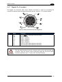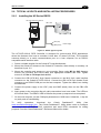
1
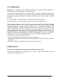
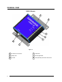
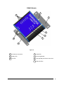
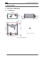
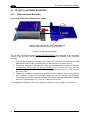
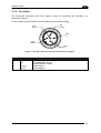
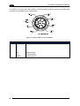
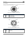
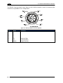
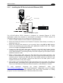
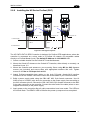
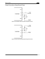
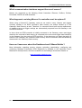
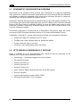
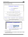
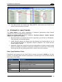
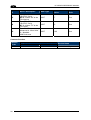
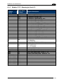
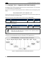
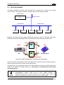
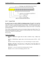
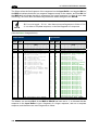
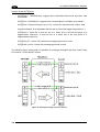
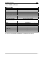
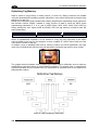
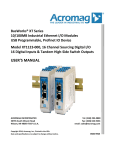
INSTALLATION
Installing the HF-Series Profibus (PBS)
CBL-1487
CBL-1487
to Configuration PC
to Configuration PC
to Configuration PC
to Configuration PC
HF-CNTL-PBS-02
w antenna
2.6.5
2
to Profibus Master
to Power Supply
PBS IN
PBS OUT
PBS IN
PBS OUT
PBS IN
PBS OUT
PBS IN
Profibus
Terminator
Cap
Figure 31 - PBS Typical Layouts
The HF-CNTL-PBS-02 RFID Controller is designed for Profibus RFID applications, where the
controller is connected as a slave node in a Profibus (DP) network via compatible cables
directly to a Profibus Master (host). The default Node ID is 63.
1. Select a suitable location for the Cobalt HF Controller/Antenna.
2. Mount the Cobalt HF Antenna to the Cobalt HF Controller, either directly or remotely, as
described in par. 2.2.
3. Mount the controller and antenna to your mounting fixture using M5 (or #10) diameter
screws (not included) and secure them with appropriate washers and nuts. Tighten
screws to 1.7 Nm or 15 lbs per inch ± 10%.
4. Attach Profibus-compatible data cables to the 5-pin B-Coded (reverse-keyed), male and
female M12 interface connectors on the Cobalt. Connect the other end of the cables to
your Profibus network.
5. Build a power supply cable using the CBL-1487 M12 5-pin female connector. Use
minimum 24 AWG wires for connection to the power supply lines according to the Vdc
connector pinout. Connect the CBL-1487 M12 5-pin female connector to the M12 5-pin
male connector on the controller. Connect the other end of the cable (wires or usersupplied connectors) to the power supply.
6. Apply power to the controller after all cable connections have been made. The LEDs on
the unit will flash. The READY LED is ON after the power up sequence has completed.
35