1
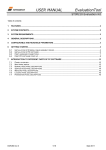
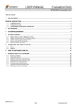
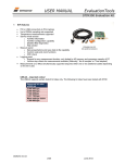
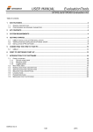
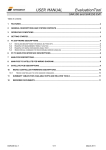
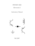
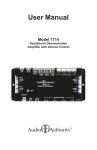
USER MANUAL EvaluationTool STIM202 Evaluation Kit Table of contents: 1 FEATURES ................................................................................................................................................................ 2 2 GENERAL DESCRIPTIONS AND SYSTEM CONTENTS ........................................................................................ 2 3 SYSTEM REQUIREMENTS ....................................................................................................................................... 3 4 GETTING STARTED .................................................................................................................................................. 3 4.1 4.2 4.3 4.4 5 INSTALLATION OF NI-SERIAL CABLE ASSEMBLY DRIVER ............................................................................................ 3 INSTALLATION OF STIM202 EVALUATION PC SOFTWARE ......................................................................................... 4 FIRST HARDWARE CONNECTION .............................................................................................................................. 4 FIRST PC SOFTWARE START-UP ............................................................................................................................. 5 INTRODUCTION TO DIFFERENT PARTS AND FEATURES OF PC SOFTWARE ................................................ 7 5.1 5.2 5.3 5.4 5.5 5.6 PANELS OVERVIEW ................................................................................................................................................ 7 NORMAL MODE PANEL DESCRIPTION....................................................................................................................... 8 SERVICE MODE PANEL DESCRIPTION ...................................................................................................................... 9 MEASURE PANEL DESCRIPTION ............................................................................................................................. 10 DEMONSTRATOR PANEL DESCRIPTION................................................................................................................... 10 PARAMETERS PANEL DESCRIPTION ....................................................................................................................... 11 6 SUMMARY TABLE FOR AVAILABLE STIM202 EVALUATION TOOLS .............................................................. 11 7 REFERRED DOCUMENTS...................................................................................................................................... 11 Figure 1: STIM202 evaluation kit hardware (STIM202 module not included) DOK333 rev.3 1/11 April 2011 USER MANUAL EvaluationTool STIM202 Evaluation Kit 1 Features 2 Up to 1000Hz sampling rate Data presentations and log to file capability (Measurement Full device configuration capability (Service Mode access) Demonstrator view (showing angular rate and integrated angle) Temperature measurements General descriptions and system contents The STIM202 evaluation kit provides rapid measurement and configuration access to the STIM202 multi-axis gyro module from Sensonor Technologies. Full device configuration, graphical result presentation, demonstration and save data to file are supported for 1, 2- or 3-axis units. The required single supply voltage (5VDC) for the module is provided from a PC or laptop USB port. System contents: Quick start manual (aprinted version of this document) STIM202 evaluation kit PC software for Windows operating systems NI USB interface cable for RS485/RS422 (for quick evaluation/device configuration), supporting bit rate = 460800 bit/s only STIM202 communication cable Included CD-ROM (or memory stick) with kit installation files and documentation STIM202 modules are ordered separately. Figure 2: STIM202 evaluation kit packing PCI cards are available as add-ons to the kit, fully compatible with the STIM202 communication cable already included. Setups with PCI cards supports all selectable STIM202 bit rates (also 374400 and 921600 bit/s). DOK333 rev.3 2/11 April 2011 USER MANUAL EvaluationTool STIM202 Evaluation Kit RS422 STIM202 communication cable RS422 USB interface cable/ PCI card/ Express card USB/ PCI STIM202 evaluation kit PC software Figure 3: STIM202 evaluation kit connections/setup schematics 3 System requirements Minimum 2 free USB ports required; One for STIM202 communication and one for STIM202 power supply. The STIM202 evaluation kit is verified on the following operating systems: 4 4.1 Windows Xp Windows Vista Windows 7 Getting started Installation of NI-Serial cable assembly driver Without connecting anything yet, start with the installation of the NI-serial driver. The driver is found on the supplier CD-ROM (included). During installation the following windows appear (exact figures listed refers to a Vista installation): Figure 4: NI-Serial installation (1 of 12) Figure 5: NI-Serial installation (2 of 12) Figure 6: NI-Serial installation (3 of 12). Selections can be left as default Figure 7: NI-Serial installation (4 of 12) Figure 8: NI-Serial installation (5 of 12) Figure 9: NI-Serial installation (6 of 12) Figure 10: NI-Serial installation (7 of 12) Figure 11: NI-Serial installation (8 of 12) Figure 15: NI-Serial installation. Installation complete (12 of 12) Figure 12: NI-Serial installation (9 of 12) DOK333 rev.3 Figure 13: NI-Serial installation (10 of 12) Figure 14: NI-Serial installation (11 of 12) 3/11 April 2011 USER MANUAL EvaluationTool STIM202 Evaluation Kit 4.2 Installation of STIM202 evaluation PC software Now, continue to install the PC software. Do this by locating the software (a zip file) on the included kit CD-ROM, or by downloading the latest PC software from Sensonor support site (http://www.sensonor.com/help-menu/support.aspx). Unzip the zip package to a local drive, and run the installation file (setup.exe.) to start the installation Follow the on-screen instructions to complete the installation During installation the following windows will appear (refered to a Vista installation): Figure 16: PC software installation (1 of 6) Figure 17: PC software installation (2 of 6) Figure 20: PC software installation (5 of 6) Figure 21: PC software installation. Installation complete (6 of 6) 4.3 Figure 18: PC software installation (3 of 6) Figure 19: PC software installation (4 of 6) First hardware connection Notice: NI-Serial driver and PC software should already be installed at this point. Connect system hardware as follows: Connect a STIM202 module to the Nicomatic connector of the STIM202 communication cable. A small screw/torx driver is normally needed for tightening the fixing screws of the Nicomatic connector to the male connector of the STIM202 Connect the 9 pin D-SUB connector in one end of the STIM202 communication cable to the NI interface cable (Alternatively, if the add-on solution is used (the PCI card); you can skip this point as the NI interface cable is not in use for this setup) Insert the USB connector of the NI interface cable into a free USB port of the stationary PC/ laptop (Alternatively, if the add-on solution is used (the PCI card as above); connect the STIM202 communication cable directly to the PCI card) Verify that the device driver installation has completed successfully. The NI-Serial device should become visible in device manager (an example for STIM202 evaluation kit USB interface device recognition is shown in Figure 22). NOTICE: At this point; Remember or write down the COM-port number as this is needed later for editing the software parameter file of the PC software DOK333 rev.3 4/11 April 2011 USER MANUAL EvaluationTool STIM202 Evaluation Kit Figure 22: Showing the verification that NI USB-485 device has become visible in the device manger after first hardware connection (the example is from a Vista-installation) 4.4 NOTE: Leave the second USB connector of STIM202 communication cable (the one for powering STIM202) unconnected at this point First PC software start-up Notice: All hardware should now already be connected, except the second USB connector for STIM202 power Proceed now to the first time start-up of PC software (and follow the step-by-step list as below): Navigate to the „STIM Evaluation‟ folder in the Windows start menu. The shortcut to start the STIM202 Evaluation Kit PC software (the shortcut to “STIM202 Evaluation Kit.exe”) should be found directly in this folder. Click to expand, and click on the link to start the program. The link is normally named “STIM202_Eval” Directly after start-up of program a pop-up box will appear and ask for a parameter file (an .INI-file). Select the INI-file available in the installation folder (C:\Program Files\STIM Evaluation by default). The file name is „STIM202 evaluation kit.INI‟ or similar The software GUI (graphical user interface) and Normal Mode panel loads and shows (by default) next, after the INI-file was selected In the parameters file (INI-file), accessible from either menu or tab in software, ensure the correct COM port number for the active device is defined. Notice also the Device-to-COM port correlation listed in the parameters view is correct. The parameters view is useful for the editing, and can be entered directly by clicking the „Parameters‟ tab in the main panel of the program. The password to enable edit of parameters is „stim‟ Notice also that the “Device” selection of the Normal Mode panel (go back to normal mode panel if needed to check) must correspond to the chosen Device and COM port selection in the parameters view. This is necessary in order to successfully establish the connection with STIM202 (in the next step). Notice also that the parameters view (actually the INI-file) only can accept already assigned port numbers, OR alternatively 0‟s for the devices that not in use, or else the connection later will fail (in the next step). There are 8 listed devices. Therefore, ensure only 0‟s are inserted for the “RS422 port # to device” rows that are not in use (normally for the devices 2 to 8) After completing the correct COM port configuration in the parameters view, press „OK‟ in upper right corner of this tab to confirm parameters setting are OK and return back to the Normal Mode by clicking directly on the Normal Mode tab Now, establish the first connection to STIM202 by clicking the „Connect to HW‟ button. Verify that a green light appears, and that the message „Hardware connected OK‟ is shown in the lower right corner of the panel. See Figure 23 for an example of how the Normal Mode panel looks like directly after such a first successful hardware connection DOK333 rev.3 5/11 April 2011 USER MANUAL EvaluationTool STIM202 Evaluation Kit Figure 23: Showing ‘Normal Mode’ panel after first hardware connection. The green LED and the text in the lower right corner confirms hardware connection is OK Change now the ‟Apply voltage‟ control switch position to ‟ON‟. A pop-up message telling to turn on power to STIM202 should appear. Proceed to turn on this power, 5V DC to STIM202, by inserting the free USB connector (of the STIM202 communication cable) into a free USB port of the PC. Confirm also the supply voltage applied by clicking the „OK‟ button on the following pop-up panel. (Notice also that this manual process controls some operations of the program.) Figure 24: Pop-up panel showing it’s time to turn on STIM202 power The kit is now ready for use, and the connection and the module communication could be checked by e.g. pressing the „Request config DG‟ button. An example of such result is shown below (in blue text in Figure 25) DOK333 rev.3 6/11 April 2011 USER MANUAL EvaluationTool STIM202 Evaluation Kit Figure 25: Result of sending ’Request config DG’ to STIM202 5 Introduction to different parts and features of PC software 5.1 Panels overview In addition to the panel already shown („Normal Mode‟ panel), some other panels are available in the PC software. Here they are listed as an introduction: Figure 26: ‘Service Mode’ panel DOK333 rev.3 Figure 27: ‘Measure’ panel 7/11 April 2011 USER MANUAL EvaluationTool STIM202 Evaluation Kit Figure 28: ‘Demo’ panel Figure 29: ‘Parameters’ panel Main panel menus: 5.2 ‘File’ → ‘Open’ : For taking a specific INI-file into use (e.g. the default “STIM202 evaluation.INI”) ‘File’ → ‘New’ : For generating a new INI-file. Notice that this new INI-file should be edited before taken into use, and that it is not a copy of any existing INI-file ‘File’ → ‘Save as’ : For saving the current „Parameters‟ content into a INI-file ‘File’ → ‘Print’ : For printing the current „Parameters‟ content at the default printer ‘File’ → ‘Exit’ : To exit program ‘Edit’ → ‘Parameters’ : To edit the „Parameters‟ content ‘Help’ → ‘About’ : About the program (software revision number etc.) Normal Mode panel description Table 1: Normal Mode panel descriptions Panel unit Connect to HW LED Disconnect from HW Apply voltage switch (On/Off) Device box Reset device button Request config DG button Request identity DG button Request serial# DG button Enter serv. mode button Response window DOK333 rev.3 Functionality and description To connect to interface hardware. Opens PC COM port according to selections in the parameter file Indicator for hardware connection. Lit GREEN when successfully connected To Disconnect from interface hardware. Closes PC COM port To be switched manually (ON or OFF) by user when asked to. Controls certain functions of the PC software Should hold the correct device number for the correct COM port number according to parameter file Resets the device (the STIM202). Sends reset command („R‟) Sends command („C‟) to receive one configuration datagram Sends command („N‟) to receive one part number datagram Sends command („I‟) to receive one serial number datagram To enter Service Mode List the response to commands from the device (from STIM202) 8/11 April 2011 USER MANUAL EvaluationTool STIM202 Evaluation Kit Figure 30: Example for result txt-file with time tags, measurement data, status byte, Rx CRC, Calc CRC and DG ID Table 2: Result file descriptions Column label T [s] AR_X [/s] AR_Y [/s] AR_Z [/s] STS RxCRC CalcCRC DG_ID Description This column holds time tag data for each row of measurement data listed X-axis rotation angular rate data, in [°/s] Y-axis rotation angular rate data, in [°/s] Z-axis rotation angular rate data, in [°/s] Status byte. Normally 0. See ref[1] for details Re-calculated CRC on receiver side (in PC software) Calculated CRC on transmitter side (in STIM202 micro controller) Datagram ID. See ref[1] for details Notice that rev G modules also support temperature measurements. For that case, the temperature information can also be logged to file. The information in such file is comparable to above, then also with descriptions and units for temperature on the first row of each column. 5.3 Service Mode panel description Service Mode is used for device configuration. Service Mode is entered by pressing „Enter serv. mode‟ button in Normal Mode. Panel units, functionality and descriptions are listed in Table 3. Exit from Service Mode is done by pressing either „Exit to Normal Mode‟ or „Exit to init mode‟ button. Notice: Changes applied by sending commands in Service Mode are stored to flash memory of STIM202 by sending the save command („s‟). Table 3: Service Mode panel descriptions Panel unit Available commands window Complete command window Send command button Command response window Erase button Save button DOK333 rev.3 Functionality and description Shows a list of available commands. See also ref[1] for details Contains the complete command to send. It is auto-completed by usage of the listings in the available commands window. Left click in the complete command window shows a list of earlier sent commands. Right click enables manual command entry Sends command to device (STIM202) Shows the response to commands (the response from STIM202). See also ref[1] for details Erases the content of the command response window Saves the content of the command response window to a text file with a detailed date and time tag 9/11 April 2011 USER MANUAL EvaluationTool STIM202 Evaluation Kit 5.4 Measure panel description Table 4: Measure panel descriptions Panel unit Measure button Samples box Save to file button X-, Y- and Z-axis check boxes CRC and DG-ID LEDS Data box Sample rate box Unit box DG type Save to disk icon Print icon 1:1 icon Zoom icon Cursor 1 Cursor 2 Delta Progress bar Lower bar on panel Functionality and description Starts a measurement series Defines the number of samples to be collected (max 50 millions) Saves data from a completed measurement series to a result file Selects which axis data to present in the graph area (up to 3 axes can be plotted) Confirms CRC and DG-ID as expected. LEDs turns red if checks fail Selects which datagram content to be shown. Several options are available (use the arrows in the left side of box for selections) Informs what sample rate has been used for the measurements Shows what are the selections for the Output unit Shows the type of datagram received Saves a picture of the plotted data to file Prints a picture of the plotted data to the default printer Resets zoom level to 1:1 Enables a custom zoom of the presented results in the strip chart (graph area) according to placement of available cursors Shows the location of cursor no 1 Shows the location of cursor no 1 Shows the delta between the two cursor locations A blue continuous line shows the measurement series progress Shows the INI-file in use and the active mode (NORMAL MODE) Save data to file feature: Measurement data can be logged to file from „Measure‟ panel‟ by clicking “Save to file” after a measurement series is completed. This result file contains several columns of tab separated data. An example of result file is shown in Figure 30. A detailed description of each column of data is found in Table 2. 5.5 Demonstrator panel description A demonstrator part of the software is found in the „demo‟ panel. Various reset times and axis scales can be selected. The STIM202 axes rate signals are handled and plotted axis by axis real-time in these windows. Curves shown are angular rate [°/s] in red, and increment angle [°] in blue. Table 5: Demonstrator panel descriptions Panel unit Measurements switch (On/Off) Reset button Reset time[s] box Scale box Strip charts (X, Y and Z) The 3 square plot areas on the right side DOK333 rev.3 Functionality and description Switches continuous measurements On/Off Does a bias cancellation on the reported STIM202 angular rate data To insert the chosen data evaluation time for bias cancellation. 1 sec is the default value Sets the max and min y-axis scale values for the three strip charts below Shows angular rate and integrated angle results Shows the integrated angle of each of the reporting STIM202 axes 10/11 April 2011 USER MANUAL EvaluationTool STIM202 Evaluation Kit 5.6 Parameters panel description Table 6: Parameters panel descriptions Panel unit ===== General parameters ===== Password Folder For Temporary Result File Storage Folder For Final Result File Storage User Interface Tab To Activate At Startup What Priority Will This Program Run With What Format to Use For Result Files ===== STIM communication ===== RS422 port # to device # list RS422 Bitrate [bit/s] RS422 Stopbit RS422 Parity RS422 Input Buffer Size RS422 Output Buffer Size ===== External Hardware ===== The GPIB Card Number To Use Type Of Power Supply In Use Interface To Power Port or Address to Power Voltage on Output Of Power Supply [V] Current Limit on Output of Power [A] 6 Functionality and description Current valid password to be able to edit the parameters list. The password is “stim” by default. Can be changed “c:\\userdata\\test\\Temp\\” by default. Can be changed by user “c:\\userdata\\test\\Final\\” by default. Can be changed by user Is Normal Mode panel by default, however can be changed Instructs the program priority for the PC operation system ASCII by default, however can be changed to 8byte binary Defining which device to be assigned to which COM port number Manual RS422 bit rate selection. NOTE: The USB serial interface cable that comes with the kit supports only the 460800 baud option for STIM202, while e.g. the add-on PCI card supports also the 374400 and 921600 baud option. Default value is “460800” 1 or 2. Default is “1” None, odd or even. Default is “None” Recommended 1000000 (as default) Recommended 1000 (as default) Normally 0 (when no GPIB card in user). If card(s) are in use; the first card will be assigned to #1, second to #2, etc. Default value is “0” Normally None (when not in use). Agilent E3631A, E3633A and E3644A supported. Default value is “None” Normally None (when not in use). RS232 (for Agilent E3631A only) and GPIB supported. Default is “GPIB” Selectable up to 31. Parameter should be neglected if not in use. Default value is “5” Can be neglected if not in use. Should be within the supply voltage range of the device; however is never to exceed the absolute maximum ratings value! (7.0V) Default value is “5.1” To limit the current consumption from the power source. Default value is “1.0” Summary table for available STIM202 evaluation tools Table 7: STIM202 Evaluation kit and available add-ons Part no 83879 84014 Description STIM202 EVALUATION KIT STIM202 NI PCI CARD RS485/RS422 2-PORT SERIAL INTERFACE (KIT ADD-ON) IMPORTANT NOTICE The hardware included in the evaluation kit supports only the default 460800 bit/s STIM202 option for RS422 datagram transmission bit rate (this is limited by hardware, by the NI USB interface cable). The available kit add-on, the PCI card which is the choice for longer measurements (characterizations) where the risk for communication errors over USB cannot be taken, the setup for stationary PCs, the setup with the best stability, supports all available transmission bit rate options for STIM202 (374400, 460800 and 921600 bit/s). 7 Referred documents Table 8: Referred documents Ref [1] Doc TS1439 DOK333 rev.3 Description Datasheet STIM202 11/11 April 2011