Download USER MANUAL EvaluationTools
Transcript
USER MANUAL
EvaluationTools
STIM300 Evaluation Kit
Table of contents:
1
EVK FEATURES ........................................................................................................................................................ 2
GENERAL DESCRIPTIONS ............................................................................................................................................. 3
1.1
1.2
1.3
STIM300 EVK PCI ............................................................................................................................................... 3
STIM300 EVK USB .............................................................................................................................................. 3
CONFIGURABLE AND READABLE PARAMETERS ......................................................................................................... 4
2
KIT CONTENTS ......................................................................................................................................................... 5
3
SYSTEM REQUIREMENTS ....................................................................................................................................... 5
4
GETTING STARTED .................................................................................................................................................. 6
4.1
4.2
4.3
4.4
4.5
5
PCI-KIT INSTALLATION OF NI SERIAL DRIVER ........................................................................................................... 7
USB KIT INSTALLATION OF FTDI SERIAL DRIVER ...................................................................................................... 8
VERIFICATION OF SERIAL DRIVER SET-UP .............................................................................................................. 10
INSTALLATION OF PC SOFTWARE .......................................................................................................................... 11
INSTALLATION OF PCI CARD ................................................................................................................................. 15
CONNECTING THE STIM TO YOUR PC ................................................................................................................ 16
5.1
5.2
PCI KIT ............................................................................................................................................................... 16
USB KIT .............................................................................................................................................................. 16
6
FIRST PC SOFTWARE START-UP ........................................................................................................................ 17
7
INTRODUCTION TO PC SOFTWARE .................................................................................................................... 22
7.1
7.2
7.3
7.4
7.5
7.6
7.7
7.8
PANELS OVERVIEW .............................................................................................................................................. 22
MAIN PANEL MENUS ............................................................................................................................................. 23
NORMAL MODE PANEL DESCRIPTIONS ................................................................................................................... 24
SERVICE MODE PANEL DESCRIPTIONS ................................................................................................................... 24
MEASURE PANEL DESCRIPTIONS ........................................................................................................................... 25
LOGGING PANEL DESCRIPTIONS ............................................................................................................................ 26
PARAMETERS PANEL DESCRIPTIONS ..................................................................................................................... 27
MESSAGES FROM THE PROGRAM .......................................................................................................................... 28
DOK373 rev.4
1/28
November 2013
USER MANUAL
EvaluationTools
STIM300 Evaluation Kit
1
EVK features
PCI or USB connectivity to PCs/ laptops
Up to 2000Hz sampling rate supported
Temperature measurements supported
Service mode access
o Full IMU information
o Full IMU configuration capability
o Detailed IMU diagnostics
o Help section
STIM300 EVK PCI
Measure panel
(the preferred solution)
o Data presentations and save data to file capability
o Custom scale and zoom functions
o CRC check
Logging panel
o Support for any measurement duration, only limited by HD memory and processor capacity of PC
o Various stop criteria for measurements available ('Manually', 'No of samples' or 'Time elapsed')
Measurements on 2 IMUs simultaneously supported (requires either one or two additional cables depending
on the kit in use)
USB-kit – important notice!
The USB kit supports certain distinct bit rates only. The following bit rates have been tested with STIM:
Approved bit rates
w/USB kit
3 000 000 bps
2 000 000 bps
1 500 000bps
1 411 765 bps
Most settings below
1 300 000 bps
DOK373 rev.4
2/28
November 2013
USER MANUAL
EvaluationTools
STIM300 Evaluation Kit
General descriptions
The STIM300 evaluation kits provide measurement and configuration access to STIM300 inertial measurement units
(IMUs). IMU configuration, graphical result presentation and save data to file functions are supported. The single
voltage supply required for IMU operation is provided from any PC or laptop USB port.
Two alternative evaluation kits are available. Features are highlighted in the following table
Table 1: Features of USB vs PCI-kit
Portability across PC-s
Hardware installation required?
Gyro, Acc, Inc & AUX-out available?
TOV, AUX-in, External trigger
available?
Transmission rate supported
1.1
USB
Yes (custom SW installation required)
No
Yes
No
PCI
No
Yes
Yes
Yes (break-out cable)
Up to 3Mbit/s
Up to 5.34Mbit/s
STIM300 EVK PCI
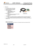
The evaluation kit with PCI connectivity is the preferred solution for thorough characterization. This kit is in the
following referred to as "PCI kit". See also the picture on the front page.
1.2
STIM300 EVK USB
The evaluation kit with USB connectivity provides the alternative solution, e.g. for laptops, and is an excellent choice
for IMU configuration and shorter measurement series. This kit is in the following referred to as "USB kit".
The kit contains a USB-RS422 converter from Future Technology Devices International, integrated with the
communication and power supply cable.
The USB-RS422 converter cable is a USB to RS422 levels serial UART converter cable incorporating FTDI’s
FT232RQ USB to serial UART interface IC device which handles all the USB signalling and protocols. The cable
provides a fast, simple way to connect devices with a RS422 interface to USB.
Each USB-RS422 cable contains a small internal electronic circuit board, utilising the FT232R, which is encapsulated
into the USB connector end of the cable. The integrated electronics also include the RS422 transceiver plus Tx and Rx
LEDs which give a visual indication of traffic on the cable.
DOK373 rev.4
3/28
November 2013
USER MANUAL
EvaluationTools
STIM300 Evaluation Kit
1.3
Configurable and readable parameters
Configurable IMU parameters:
Output format (angular rate, increment angle, etc.)
Datagram format (standard, extended, etc.)
Sampling rate (125 samples/s, 250 samples/s, etc.)
Bandwidth/ Low pass filter frequency (16Hz, 33Hz, etc.)
RS422 transmission bit rate (374400 bits/s, 460800 bits/s, etc.)
Number of stop bits in datagram (1 or 2 stop bits)
Parity bit (no parity, odd parity, even parity)
Line/ Datagram termination (on/off, None/ <CR><LF>)
Readable IMU parameters:
Unit part number
Serial number
Firmware revision
Hardware revision
Guro module diagonistics
Detailed IMU diagnostic information includes RAM and flash checks, stack handling checks, status of internal voltage
supply references, and various parameter reports for each measurement axis are available from the supported
SERVICE mode.
Note: Time of Validity (TOV) and external trigger functionalities of STIM300 are not supported by the EVK PCsoftware.
DOK373 rev.4
4/28
November 2013
USER MANUAL
EvaluationTools
STIM300 Evaluation Kit
2
Kit contents
PCI kit only:
o PCI to RS422 interface card, "the PCI card", for the PCI kit
o STIM300 communication and power cable
USB kit only
o USB to RS422 interface cable
Memory stick with
o PC software,
o FTDI CDM20824 serial driver for Windows and
o EVK PC sotware User manual
Allen Wrench for fixing connector of communication and power cable to IMU
Hard copy of User manual
Note that the evaluation kits does not include the IMU. (The IMU is to be ordered separately.)
3
System requirements
Windows XP SP2 (or later), Windows Vista, Windows 7 (32/ 64bit)
1 free USB port and 1 free PCI slot for the PCI kit
2 free USB ports for the USB kit
Quad core processor recommended (when simultaneously logging data from two IMUs)
DOK373 rev.4
5/28
November 2013
USER MANUAL
EvaluationTools
STIM300 Evaluation Kit
4
Getting started
Preparing your system involves the following steps, depending on type kit:
PCI
USB
4.1 NI serial driver
installation
4.2 FTDI serial driver
installation
4.3 Serial driver verification
4.4 EVK PC-software installation
4.5 PCI-card
installation
DOK373 rev.4
6/28
November 2013
USER MANUAL
EvaluationTools
STIM300 Evaluation Kit
4.1
PCI-kit Installation of NI serial driver
Install the National Instruments (NI) serial driver from the memory stick included in the kit. This process is selfinstructive. Follow the on-screen messages without doing any configuration changes.
Figure 1 and Figure 2 show two of the messages that appear during serial driver installation.
The NI serial driver can also be found from the Sensonor support site. Use this site to regularly check for updates.
Figure 1: NI serial driver installation summary
Figure 2: NI serial driver
DOK373 rev.4
7/28
November 2013
USER MANUAL
EvaluationTools
STIM300 Evaluation Kit
4.2
USB kit Installation of FTDI serial driver
To install the drivers for the FTDI serial driver under Windows, follow the instructions below:
Connect the USB-RS422 plug to a spare USB port on your PC.
If there is an available Internet connection, some Windows versions will silently connect to the Windows
Update website and install any suitable driver it finds for the device.
In the event that no automatic installation takes place, please refer to the set-up guide from FTDI:
http://www.ftdichip.com/Support/Documents/InstallGuides.htm
Then modify the port configuration as follows:
Open device manager:
Select "USB Serial Port (COM<n>)"
DOK373 rev.4
8/28
November 2013
USER MANUAL
EvaluationTools
STIM300 Evaluation Kit
Select "Advanced" from the "Port Setting" pane.
Reduce the "Receive (Bytes)"-setting to a small value, such as 256. Other settings may be left untouched.
Press OK twice.
Remember to restart the computer after making this change.
DOK373 rev.4
9/28
November 2013
USER MANUAL
EvaluationTools
STIM300 Evaluation Kit
4.3
Verification of serial driver set-up
Using your PC, launch Device Manager Device Manager. See Control Panel -> Hardware and Sound.
Verify that the serial driver installation has completed successfully. Examples are shown in Figure 3a (PCI) and Figure
3b (USB).
Notice at this point the assigned COM port value(s) as this information is needed later for connecting to the IMU(s)
from the PC software
Figure 3a: COM port assignments for PCI card cable in Windows 7
Figure 4b: COM port assignments for USB cable in Windows 7
DOK373 rev.4
10/28
November 2013
USER MANUAL
EvaluationTools
STIM300 Evaluation Kit
4.4
Installation of PC software
Install the PC software by running "setup.exe" found on the included memory-stick. Follow the on-screen instructions
to complete the installation. See the following figures for guidance.
Notice that the PC software also can be downloaded from the Sensonor support site. Use this site regularly to check
for updates.
Figure 5: PC software installation (1 of 6). Installer initializes
DOK373 rev.4
11/28
November 2013
USER MANUAL
EvaluationTools
STIM300 Evaluation Kit
Figure 6: PC software installation (2 of 6)
Figure 7: PC software installation (3 of 6)
DOK373 rev.4
12/28
November 2013
USER MANUAL
EvaluationTools
STIM300 Evaluation Kit
Figure 8: PC software installation (4 of 6)
Figure 9: PC software installation (5 of 6). Installation complete
DOK373 rev.4
13/28
November 2013
USER MANUAL
EvaluationTools
STIM300 Evaluation Kit
Figure 10: PC software installation (6 of 6). Installation complete
DOK373 rev.4
14/28
November 2013
USER MANUAL
EvaluationTools
STIM300 Evaluation Kit
4.5
Installation of PCI card
Disconnect AC and battery power from your computer before attempting installation.
Following your computer manufacturer's directions, install the PCI card into a free PCI slot of the PC cabinet.
DOK373 rev.4
15/28
November 2013
USER MANUAL
EvaluationTools
STIM300 Evaluation Kit
5
5.1
Connecting the STIM to your PC
PCI kit
USB
Power cable to
USB port
Micro-D
Comm cable to
PCI-card port
D-SUB9
5.2
USB kit
P-USB
Power cable to
joint: 0.4m
Main cable joint: 1.2 m
Micro-D
Comm cable to
joint: 0.4m
C-USB
DOK373 rev.4
16/28
November 2013
USER MANUAL
EvaluationTools
STIM300 Evaluation Kit
6
First PC software start-up
1. Navigate to the ‘Sensonor evaluation tools’ folder from Windows start menu. Click on the shortcut named
"STIM300 EVK" to start the PC software. Ensure to run program as administrator (as this is needed for full
function)
Figure 11: Starting PC software from Windows 7 start menu
2. A pop-up box for software registration appears. Fill in four open fields and click "Submit". The default email
client opens. Press "Send" in order to complete this step (and the user information is sent back to Sensonor)
Figure 12: Welcome message and software registration
DOK373 rev.4
17/28
November 2013
USER MANUAL
EvaluationTools
STIM300 Evaluation Kit
3. A pop-up box appears, asking for a parameter (.INI) file. Select the INI-file (available in the installation folder by
default) and click "Load"
Figure 13: INI-file selection
4. The Normal mode panel is shown
Figure 14: Normal mode panel after selecting INI-file
DOK373 rev.4
18/28
November 2013
USER MANUAL
EvaluationTools
STIM300 Evaluation Kit
5. Verify the correct COM port settings in the Parameters view. Password to edit is ‘stim’. If needed change the
existing setting by double clicking on the value '4'
Figure 15: Edit the INI-file in order to verify correct COM port settings
6. Set the correct value for RS422 bit rate, according to the configuration of the STIM unit:
Figure 16: Edit parameters, here RS422 bit rate
DOK373 rev.4
19/28
November 2013
USER MANUAL
EvaluationTools
STIM300 Evaluation Kit
USB-kit – important notice!
The USB kit support certain distinct bit rates only. The following bit rates have been tested with STIM:
Table 2: Service mode panel descriptions
Approved bit rates
w/USB kit
3 000 000 bps
2 000 000 bps
1 500 000bps
1 411 765 bps
Most settings below
1 300 000 bps
7. Establish connection to module by clicking the ‘Connect to HW’ button in Normal mode panel. A green LED light
appears, indicating that the COM port(s) is (are) opened.
Figure 17: Normal mode panel after first hardware connection
8. Change the ’Apply voltage’ control switch position to ’On’. The pop-up message telling "Turn on device supply
voltage" appears. Do this by inserting the red "POWER" USB connector of the STIM300 communication and
power cable into a free USB port of the PC/ laptop. Confirm the supply voltage applied by clicking ‘OK’ on the
pop-up message
DOK373 rev.4
20/28
November 2013
USER MANUAL
EvaluationTools
STIM300 Evaluation Kit
Figure 18: Normal mode panel when USB power connector of STIM300 communication and power cable is to be inserted
9. Verify the connection to module by clicking on the ‘Request config DG’ button. An example of such a result is
shown in Figure 19. (The kit is now ready for use !)
Figure 19: Result of sending ’Request config DG’ to the IMU
DOK373 rev.4
21/28
November 2013
USER MANUAL
EvaluationTools
STIM300 Evaluation Kit
7
Introduction to PC software
7.1
Panels overview
In addition to the panel already shown (Normal mode and Parameters panel), other panels are also available:
Figure 20: Service mode panel
Figure 21: Measure panel
DOK373 rev.4
22/28
November 2013
USER MANUAL
EvaluationTools
STIM300 Evaluation Kit
Figure 22: Logging panel (for saving data to file)
7.2
Main panel menus
Menu
‘File’ → ‘New parameter file’
‘File’ → ‘Open parameter file’
‘File’ → ‘Save parameter file as’
‘File’ → ‘Print parameters’
‘File’ → ‘Edit parameters’
‘File’ → ‘Exit’
‘Help’ → ‘Check for updates’
‘Help’ → ‘About’
Description
For creating a new INI-file. Notice that this new INI-file also needs be edited by
the user before taken into use. The content is not equal to any existing INI-files.
Notice also that the Parameters view in the software is not updated with the new
INI-file content until the user clicks the "Edit" button (this triggers an update of this
view)
For opening and taking a specific INI-file into use
To save current parameter settigs into a new INI-file
For printing the current ‘Parameters’ content at the default printer
To edit the ‘Parameters’ content
To exit program
Opens the Sensonor support site in a web browser. NI serial drivers, any PC
software updates and new releases of User manuals can be obtained from here
About the program (Program name, publisher and software revision number)
Figure 24: Help menu
Figure 23: File Menu
DOK373 rev.4
23/28
November 2013
USER MANUAL
EvaluationTools
STIM300 Evaluation Kit
7.3
Normal mode panel descriptions
Table 3: Normal mode panel descriptions
Panel unit
Connect to HW
LED
Disconnect from HW
Apply voltage switch (On/Off)
Device box
Reset device button
Request config DG button
Request identity DG button
Request serial# DG button
Response window
7.4
Functionality and description
To connect to interface hardware. Opens PC COM port according to selections in
active parameter file
Indicator for hardware connection. A GREEN light indicates the corresponding COM
port is opened
To Disconnect from interface hardware. Closes the corresponding COM port
To be switched manually (ON or OFF) by user when asked to. Controls certain
functions of the PC software
Should hold the correct IMU (device) number according to active parameter file.
Choice depends on which IMU and COM port the user wants to operate
Resets the IMU. Sends reset command (‘R’)
Sends command (‘C’) to receive configuration datagram
Sends command (‘N’) to receive part number datagram
Sends command (‘I’) to receive serial number datagram
Lists responses from the IMU
Service mode panel descriptions
Service mode is used for IMU configuration.
Service mode is entered by clicking on the Service mode tab next to the Normal mode tab. Panel units, functionalities
and descriptions are listed in Table 4. Exit from IMU Service mode to Normal mode is done by pressing one of the
other panel tabs (Normal, Logging, Service or Parameter panel tab).
Note: Changes made for the IMU in Service mode are only stored permanently in IMU flash memory when the save
command (‘s’) is issued.
Table 4: Service mode panel descriptions
Panel unit
Available commands window
Complete command window
Send command button
Active device indicator
Command response window
Erase button
Save button
Functionality and description
Shows a list of available commands. See product datasheet for details
Contains the complete command to send. It is auto-completed by usage of the
listings in the available commands window. Left click in the complete command
window shows a list of earlier sent commands. Right click enables manual command
entry
Sends command to the IMU
Informs about the active IMU (device). Corresponding COM port is according to the
active parameter file
Shows the responses from the IMU. See product datasheet for details
Erases the content of the command response window
Saves the content of the command response window to a text file with a detailed
date and time tag
DOK373 rev.4
24/28
November 2013
USER MANUAL
EvaluationTools
STIM300 Evaluation Kit
7.5
Measure panel descriptions
Table 5: Measure panel descriptions
Panel unit
Measure button
Samples box
Save to file button
X-, Y- and Z-axis check boxes
Active device indicator
CRC and DG-ID LEDS
Data box
Scale box
Sample rate box
Unit box
DG type box
Save to disk icon
Print icon
1:1 icon
Zoom icon
Cursors (On/Off) switch
Cursor 1
Cursor 2
Delta
Progress bar
Lower bar on panel
Functionality and description
Starts a measurement series
Defines the number of samples to be collected (max 50 millions)
Saves data from a completed measurement series to a result file. The file path
defined in the active parameter file is proposed
Selects which axis data to present in the graph area (up to 3 axes can be plotted)
Informs about the active IMU (device). Corresponding COM port is according to the
active parameter file
Confirms all CRC checks and DG-IDs as expected. Normally GREEN. LEDs turn
RED if checks fail
Selects which datagram content to be shown. Several options are available,
depending on the active datagram type. Use the arrows in the left side of box to
scroll between available selections. The plot updates immediately if a measurement
series has already been done.
Enables user to select between different scales (Full range, User defined, or Auto)
Informs what sample rate has been used for the measurements
Indicated the active Output unit (Angular Rate, Incremental Angle, etc.)
Shows the type of datagram received
Saves a picture of the plotted data to file
Prints a picture of the plotted data to the default printer
Resets zoom level to 1:1 (if ZOOM is active. See below)
Enables a custom zoom of the presented results in the strip chart (graph area)
according to placement of available cursors
Enables usage of cursors (default is Off)
Shows the location of cursor no 1
Shows the location of cursor no 1
Shows the delta between the two cursor locations (X and Y values)
A blue continuous line shows the measurement series progress
Shows the INI-file in use and the active mode (NORMAL MODE)
Save data to file from measure panel:
An example of a result file is shown in Figure 25, for a standard datagram measurement series of device # 1. A
description of each of the columns of the data log file is found in the table that follows.
Figure 25: Result file example
DOK373 rev.4
25/28
November 2013
USER MANUAL
EvaluationTools
STIM300 Evaluation Kit
Table 6: Result file example. (Standard datagram content written to file)
DG-type
Col. #
Standard
1
2
3
4
5
6
7
8
7.6
Heading
Time[s]
GYRO_X
GYRO_Y
GYRO_Z
STS
RxCRC
CalcCRC
DG_ID
Comments
Time in seconds
Gyro signal X-axis
Gyro signal Y-axis
Gyro signal Z-axis
Status-byte
Received CRC
Calculated CRC
Datagram identifier
Logging panel descriptions
Table 7: Logging panel descriptions
Panel unit
Start button
Stop button
Stop criteria slide
Samples box
Time elapsed
Samples acq.
CRC_errors
Resynch’s
Functionality and description
Starts data logging
Stops data logging
User selections between “manually”, “no of samples” and “Time
elapsed” for stopping a measurement series
In use when defining a series length with “no of samples”
Shows the real time for the test running
Shows number of samples acquired
Shows number of CRC errors (normally 0, otherwise the user should
consider to reject results data in any analysis)
Increments from 0 to a number if any re-synchronisations are needed in
order to re-establish data collections from module
Log to file capability:
Quad core processor is recommended when measuring on two IMUs simultaneously
The size of the log file is only limited by the free memory of the hard disk(s) in use
The path for result file storage is defined in the active parameter file
The program should be run as administrator to ensure the necessary rights to establish result files
DOK373 rev.4
26/28
November 2013
USER MANUAL
EvaluationTools
STIM300 Evaluation Kit
7.7
Parameters panel descriptions
Table 8: Parameters panel descriptions
Panel unit
===== General parameters =====
Password
Folder for result-file storage
What priority will this program run with
What format to use for result files
===== Device communication =====
IMPORTANT MESSAGE: Always verify
hardware connections and COM port settings
before trying to connect to the device
RS422 port # to device 1
RS422 port # to device 2
RS422 Bitrate [bit/s]
RS422 Stopbit
RS422 parity
===== External Hardware =====
The GPIB-card # to use
Type of power supply used
Interface that the power is connected with
Port or address to power
Voltage on output of power supply [V]
Current limit on output of power [A]
Functionality and description
Current valid password to be able to edit the parameters list. The
password is “stim”
“c:\userdata\test\
Instructs the program priority for the PC operation system
ASCII text by default. Can be changed to 8 byte binary
Defining which COM port # to be assigned to IMU (device) # 1
Defining which COM port # to be assigned to IMU (device) # 2
Manual RS422 bit rate selection. NOTE that USB cable that comes
with the USB kit, supports only the default 460800 bits/s option, while
the PCI card of the PCI kit supports all available bit rates
1 or 2. Default is “1”
None, odd or even. Default is “None”
If card(s) are in use; the first card will be assigned to #0, second to
#1, etc. Default value is “0”
Normally "None" (when not in use). Agilent E3631A, E3633A and
E3644A supported. Default value is “None”
Normally "None" (when not in use). RS232 (for Agilent E3631A only)
and GPIB supported. Default is “None”
Normally "0", when not in use. Selectable up to 31. Default is “0”
Default value is “5.1”. Can be neglected if not in use. Value should
be within the supply voltage range of the IMU. Clicking on the arrow
of the control unit when editing this parameter allows for voltages as
high as 6.0V maximum. Manual entry allows even higher values,
however with a warning. Note: The entered value/ voltage applied to
the IMU should never exceed the absolute maximum ratings value
for the supply voltage of the IMU (maximum 7.0V)
Default value is “1.0”. To limit the current consumption from the
power source
DOK373 rev.4
27/28
November 2013
USER MANUAL
EvaluationTools
STIM300 Evaluation Kit
7.8
Messages from the program
Messages that the program can display are listed in Table 9:
Table 9: Possible messages given by the program
#
Message
Description
1
This application is already running!
Stop loading of 2. instance...
The program is already started, a second instance will not be allowed
2
Wrong password entered!
The password entered does not match the required one for this INI-file
3
No response to message was received
Did not receive the expected response to sent service-mode command
4
There is no measurement data available for storage
To be able to save measurement data, there must be data available
5
Unable to open the selected file
Saving of measurement data failed, unable to open or create the
selected file
6
Unable to allocate the required memory
Failed to acquire the requested number of datagrams from the IMU due
to error when trying to allocate memory for temporary storage
7
No product identification datagram received
Even after retries the, expected datagram is not received as response to
command sent
8
No configuration datagram received
Even after retries the, expected datagram is not received as response to
command sent
9
No serial number datagram received
Even after reties the, expected datagram is not received as response to
command sent
10
No datagrams received
Failed to acquire the requested number of datagrams from the IMU, no
recognizable datagrams received
11
Turn off device supply voltage
Instruction to user when running without controlled power-supply
12
Turn on device supply voltage
Instruction to user when running without controlled power-supply
13
Error encountered when trying to control voltage
Failed to control the specified power-supply
14
Unexpected DG-ID received !
When waiting for datagrams, unexpected datagrams are received
15
Unable to read config DG to determine output unit !
Unable to read configuration datagram to determine the output unit
16
Unable to synch with DG-stream !
Failed to acquire the requested number of datagrams from the IMU,
unable to get in synch with datagram stream
17
Error encountered when trying to print, check configuration !
Failed to print the graph, check that a printer is configured
18
Unable to create result-folder specified by parameter !
The specified pathname can not be created, either due to access-rights
or errors in the path specification
19
Unable to enter service-mode !
Unable to enter service-mode, does not receive expected response to
command.
20
Unable to save parameters to active INI-file !
Error encountered when trying to save parameters onto INI-file
21
Edit-mode of parameters is active, unable to exit !
The edit-mode of parameters are active, unable to exit the program until
edit mode is ended
22
You are about to change the RS422 bit rate.
If are you using the USB kit hardware provided by Sensonor, please
notice that you will not be able to communicate with the device if you
change to something else than supported 460800 b/s!
For the PCI card there are no worries - it supports all available bit
rates
A warning to the user about limitations for certain RS422 hardware
23
Unable to create/save to selected file, check access rights to folder
Unable to open or create the specified file in the selected folder, try
another filename and/or location. The reason may be lacking access
rights to the folder, or illegal filename format
24
Unsupported datagram received
When trying to read datagrams into memory a datagram type not
supported by the EVK is detected
DOK373 rev.4
28/28
November 2013


