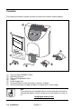
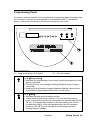
1
PERFECT 2040
Operating Manual
PERFECT 2040
Time recorder
Manual for the operation, installation, commissioning,
maintenance and troubleshooting of the time recorder.
Copyright © ISGUS J. Schlenker-Grusen GmbH 2001 - 2005
The company ISGUS J. Schlenker-Grusen GmbH claims copyright protection for
this documentation. No part of this documentation may be amended, extended,
reproduced or by any means of infringement on other legitimate interests without the
prior written permission of ISGUS.
With the exception of component parts changes, ISGUS has made every effort to
keep the contents of this manual current and correct at the time of publication.
However, we cannot guarantee the documentation to be 100% accurate.
Should you find any errors in this document, please let us know.
We are always grateful for suggestions and comments from our customers.
Edition
009CA. 0305 09 BA 2O
2.34
Printed in Federal Republic of Germany
Ref. no.
7169
ISGUS
J. Schlenker-Grusen GmbH
Oberdorfstraße 18 - 22
DE - 78 054 Villingen-Schwenningen
LISTED
I.T.E.
1DD8
WARNING
This Equipment has been tested and found to comply with the limits for a
Class B digital device, pursuant to Part 15 of the FCC Rules.
These limits are designed to provide reasonable protection against harmful
interference in a residential installation.
This equipment generates, uses and can radiate radio frequency energy
and, if not installed and used in accordance with the instructions, may
cause harmful interference to radio communications.
Only peripherals certified to comply with the Class B limits may be
attached to this equipment.
However, there is no guarantee that interference will not occur in a
particular installation.
If this equipment does cause harmful interference to radio or television
reception, which can be determined by tuning the equipment off and on,
the user is encouraged to try to correct the interference by one or more of
the following measures:
− Reorient or relocate the receiving antenna.
− Increase the separation between the
equipment and receiver.
− Connect the equipment into an outlet on a
circuit different from that to which the
receiver is connected.
− Consult the dealer or an experienced
radio/TV technician for help.
Safety instructions
Designated use
•
The PERFECT 2040 time recorder is exclusively designed for the printing of
time and date information on manufacturer approved time cards, which is the
only designated use of this machine, as described in this manual.
•
Using the time recorder for purposes other than that described above is
considered contrary to its designated use. The manufacturer cannot be held
liable for any damage resulting from such use. The risk of misuse of the time
recorder lies entirely with the user.
•
The time recorder has no explosive environment protection. The use of the
recorder in an explosive hazardous area is contrary to its designated use. The
manufacturer and/or dealer cannot be held liable for any damage resulting
from installation and use of the time recorder in such areas.
•
Operating the time recorder within the limits of its designated use requires that
you follow the instructions set out in the operating manual.
•
All service work on the time recorder must be done by trained technicians who
are familiar with the time recorder and have been instructed in safety
precautions.
•
All applicable local and national safety regulations must be observed in the
installation, use, and maintenance of the time recorder.
•
Modifications to the time recorder made without the authorization of the
manufacturer will negate the manufacturer’s responsibility and liability.
Hints for the user
•
Before installing and programming the time recorder, the operator must read
the operating instructions and safety notes.
•
The time recorder should only be opened by competent and trained personnel.
•
The external power supply must be unplugged during maintenance and repair.
The person performing the service must also ensure that all wiring entering or
leaving the time recorder is electrical current-free before beginning work.
•
Improper changing of the lithium battery may result in explosion. Do not use
batteries other than those specified by the manufacturer. Send the replaced
batteries to the recycling process available in your area.
•
Any changes or service to the electrical components of the unit must be
carried out by a qualified electrical technician.
•
In addition to reading the operating instructions, the user should be instructed
in all other generally applicable legal and other mandatory regulations relevant
to accident prevention and environment protection.
Hints for the recorder's safety
•
The time recorder has been built to the highest standards and conforms to
recognized safety rules. Nevertheless, its use may constitute a risk to the user
or third parties, or cause damage to the unit and to other property.
•
Operate the time recorder only with the power supply being part of the time
recorder package.
•
The time recorder must only be used in a suitable environment, in accordance
with its designated use and the instructions set out in this operating manual.
Any equipment or functional problems, especially those affecting the safety of
the unit and users of the unit, should be repaired immediately.
•
UL approval void if no approved batteries are installed.
•
Replacement parts must comply with the technical requirements specified by
the manufacturer. This is guaranteed only when you use the manufacturer’s
original replacement parts. Use of non-conforming parts voids your warranty.
•
Unplug and switch the unit off immediately if a problem occurs in the electrical
system.
•
Installation and mounting of the unit must be done by trained personnel.
•
Plug the time recorder power supply into a sufficiently grounded electrical
outlet.
•
Ensure that all consumables and replaced parts are disposed of safely and
with minimum environmental impact.
Warning!
This symbol focuses the user's attention to special procedures
and in the handling of the time recorder that could cause serious
injuries if the instructions are not followed carefully.
Attention
This symbol indicates that there may be danger to the time
recorder if the text is not read or the procedure is not followed.
Data may be lost or the recorder may be damaged.
Hint
This symbol indicates useful information and recommendations
for the handling of the time recorder.
Chapter 0
Contents
Chap. 1 Introduction ........................................................
Product Overview ................................................
How to Use This Manual......................................
Symbols and Abbreviations ................................................
Chap. 2 Features ..............................................................
PERFECT 2040 .....................................................
Recorder Construction........................................
Time Recorder Identification ..............................
Chap. 3 Installation............................................................
Contents ...............................................................
Selecting a Location ............................................
General Conditions.............................................................
Specific Conditions for the Time Recorder .........................
Time Recorder Installation..................................
Installation for Table Operation ......................................
Wall Mounting...................................................................
Open the Recorder.............................................................
Close the Recorder ............................................................
Remove the Metal Back Plate ............................................
Wall Mounting.....................................................................
Connect the Power Supply.................................................
Connect Additional Functions.............................................
Chap. 4 Getting Started.....................................................
Preparations.........................................................
Preparations.......................................................................
Open the Recorder.............................................................
Powering Up The Time Recorder .......................................
Powering Down the Time Recorder....................................
Programming Panel .............................................
Date / Time............................................................
Setting the Time only..........................................................
Set Time of Slave Clocks (optional) ...................................
Programming .......................................................
Chapter 0
1-1
1-2
1-3
1-4
2-1
2-2
2-4
2-5
3-1
3-2
3-3
3-3
3-3
3-4
3-4
3-5
3-6
3-7
3-7
3-8
3-8
3-10
4-1
4-3
4-3
4-3
4-3
4-4
4-5
4-7
4-9
4-10
4-13
Contents 0-1
Calling up the Programming Routine
for the Main Programming Menu ........................................
Print Format ......................................................................
Punch Rounding ...............................................................
Totals Rounding ...............................................................
IN Punch Revisions ..........................................................
Change or Delete Values for schedules
with IN Punch Revisions .....................................................
OUT Punch Revisions ......................................................
Change or Delete Values for schedules
with OUT Punch Revisions .................................................
Automatic Break ...............................................................
Fixed Break (Non Accumulation Times ..........................
Change or Delete Values for Fixed Break
(no accumulation) Time Ranges .........................................
Red Print (Ribbon Color Change)....................................
Change or Delete Values for Red Print /
Ribbon Color Changes........................................................
Overtime ............................................................................
Option Menu ........................................................
Calling up the Programming Routine for
the Options Menu ...............................................................
Daylight Savings Time......................................................
Deleting Cards ..................................................................
Maximum Presence ..........................................................
Date Format.......................................................................
Day End .............................................................................
Day Extend ........................................................................
Overtime 2 .........................................................................
Public Holidays .................................................................
Deleting Public Holidays .....................................................
Card Initialization ................................................................
Duplicate Punch................................................................
Reproducing Card ............................................................
Summary by Cards ...........................................................
Lock Out ............................................................................
Change or Delete Values for Lock Out Schedules..............
Signal Operation ...............................................................
Change or Delete Values for Signal Operation ...................
Slave clock function .........................................................
Master Clock Function .....................................................
Synchronize the Slave Clocks ............................................
Card Validity Duration ......................................................
Quit Programming Mode..................................................
Commissioning after Power Failure................................
Service Call .......................................................................
Print out of Program Settings..........................................
Chap. 5 Operation .............................................................
Punching at the Recorder...................................
Card Structure / Card Print ..............................................
Requirements for Trouble Free Time Recording.................
0-2 Contents
Chapter 0
4-14
4-15
4-19
4-22
4-25
4-31
4-32
4-38
4-39
4-47
4-52
4-53
4-57
4-58
4-63
4-63
4-65
4-69
4-70
4-72
4-73
4-75
4-77
4-82
4-84
4-85
4-87
4-88
4-88
4-89
4-93
4-94
4-98
4-99
4-100
4-101
4-103
4-105
4-105
4-106
4-108
5-1
5-2
5-2
5-4
IN / OUT Punches ..............................................................
Double Punch Disabling .....................................................
Forgotten OUT Punches (Max On).....................................
Card Full.............................................................................
Card Management / Card Organization..............
What to Know about Card Usage .......................................
Card Management Options ................................................
Deleting Cards without Carryover.......................................
Deleting Cards with Carryover of Totals.............................
Deleting Cards with Carryover of Weekly Qualification
Hours and Deletion of Totals ..............................................
Reproducing Time Card .....................................................
Summary by Cards ..............................................
Standby operation ...............................................
Chap. 6 Trouble Shooting .................................................
Error Messages....................................................
Change of Fuse for Signal Output......................
Removing of the Battery Pack ............................
Adjustment of Card Sensor ................................
Cleaning of the Card Sensor...............................
Service Call ..........................................................
Chap. 7 Maintenance .........................................................
Ribbon Change ....................................................
Cleaning the Time Recorder ...............................
Service Call ..........................................................
App. A
App. B
App. C
App. D
App. E
Technical Specifications .....................................
Default Program Settings....................................
Program Settings.................................................
Conversion table for minute print formats ........
Local Sales and Service Dealer ..........................
Chapter 0
5-5
5-6
5-7
5-8
5-9
5-9
5-10
5-13
5-14
5-16
5-19
5-21
5-24
6-1
6-2
6-3
6-4
6-5
6-6
6-8
7-1
7-2
7-4
7-4
A-1
B-1
C-1
D-1
E-1
Contents 0-3
0-4 Contents
Chapter 0
Chapter 1
Introduction
Product Overview.............................................................. 1-2
How to Use This Manual ................................................... 1-3
Symbols and Abbreviations..................................... 1-4
Chapter 1
Introduction 1-1
Product Overview
The PERFECT series of microprocessor based time recorders are available in
several configurations.
The series is separated into two classifications - non-calculating and
calculating.
The models P2005, and P2020 are non-calculating time recorders. They print
the time of daily arrivals and departures on time cards.
The models P2030 and P2040 are calculating time recorders. In addition to
printing daily arrival and departure times on a time card, they calculate the
elapsed time between punches (according to user defined workplace rules)
and print the various totals.
Common features of all PERFECT time recorders are their ease of
programming, user friendly interface and minimum maintenance requirements.
After programming, the time recorder’s operation is fully automatic. Each time
recorder is equipped with automatic daylight savings time change capability; a
perpetual calendar to adjust for leap years and month-end date changes; and
a reliable quartz time base with battery back-up during power failures. Many
PERFECT models can be equipped with additional features such as audible
signal control, synchronized time operation, and battery standby to allow time
recorder registrations during power failures.
This manual gives you step by step instructions on the operation of the
PERFECT 2040 time recorder. It documents all important functions which are
available to users.
We recommend that you carefully read this manual, before the commissioning
and use of the time recorder. To save time, please keep it in a handy location
for future reference.
All recorders are of utmost reliability and have passed thorough quality
assurance tests. Nevertheless, if there should be any problems which are not
covered by this manual, please contact your local dealer or e-mail us at:
[email protected]
1-2 Introduction
Chapter 1
How to Use This Manual
This manual will help you become familiar with the time recorder, and how to use the
designated application possibilities with its many features.
Before using the time recorder, please read and study this manual. Pay particular
attention to the pages with safety instructions.
The manual provides you with all of the important information required for the safe
and efficient use of the time recorder. Following the instructions in this manual will
help you to avoid danger and maximize the benefits from the use of the time
recorder.
Chapter 1 "Introduction", contains general information about this recorder and
about the structure of this manual.
Chapter 2 "Features", describes the functions of the PERFECT 2040 time recorder
with illustrations and easy to understand explanations.
Chapter 3 "Installation", discusses how to assemble and connect the time recorder.
Before installing the time recorder please pay close attention to the required
installation conditions.
Chapter 4 "Getting Started", teaches you how to prepare and program the time
recorder for your application. This chapter takes you through a step by step
instruction guide on the programming panel, setting of the date and time, various
menu items and options, and how the programming routine works.
Chapter 5 "Operation", explains how to use the time recorder and provides a
description of how the recorder functions in standby operation.
Chapter 6 "Trouble Shooting", provides an explanation of the internal diagnostics
built into the PERFECT 2040 and the corresponding messages. The chapter
documents most service problems and lists possible solutions.
Chapter 7 "Maintenance", provides instruction on the periodic servicing of the time
recorder that is required to guarantee top performance. Due to environmental
conditions where the time recorder may be installed, the user is encouraged to
occasionally clean the machine and change the ink ribbon.
Appendix A "Technical Specifications", provides a summary of the time recorder’s
physical and electrical characteristics.
Appendix B "Default Program Settings", lists the time recorder’s standard program
that was pre-set at the factory.
Chapter 1
Introduction 1-3
Appendix C "Program Settings", is a blank document to assist you in the planning
and recording of your time recorder’s programming.
Appendix D contains a conversion table for the individual minute print formats.
Symbols and Abbreviations
To make the reading of this manual easier, symbols and pictures are used.
These symbols and pictures may be placed at the edge of a page or they may be
inserted into text or table areas of the manual.
Warning!
This symbol focuses the user's attention to special procedures in
the handling of the time recorder that could cause serious
personal injury if the instructions are not followed carefully .
Attention
This symbol indicates that there may be danger to the time
recorder if the text is not read or the procedure is not followed.
Data may be lost or the recorder may be damaged.
Hint
This symbol indicates useful information and recommendations
for the handling of the time recorder.
1-4 Introduction
Chapter 1
Chapter 2
Features
PERFECT 2040................................................................... 2-2
Recorder Construction ..................................................... 2-4
Time Recorder Identification ............................................ 2-5
Chapter 2
Features 2-1
PERFECT 2040
The PERFECT 2040 is a calculating time recorder that records the time and date of
the arrival and departure of employees. The recorded time is printed on a bar-coded
time card with distinct, pre-printed “In / Out” columns.
The time recorder also has the ability to calculate the elapsed time between an “In”
and an “Out” punch and immediately print user defined totals in distinct columns that
are pre-printed on the time card. The totals printed are arrived at after the application
of certain global workplace rules that the user programs.
Employee use of the time recorder is very simple. When the employee inserts the
time card into the card receiver, the time recorder automatically pulls the time card
into the printer and aligns it for a precise print registration in the appropriate In / Out
column. Once the printing function is completed, the time recorder releases the card
and the employee can remove it for placing in a nearby card storage rack.
The dot matrix printer of the PERFECT is maintenance-free. In addition, bicolored
ribbons enable the time recorder to highlight in red ink any attendance irregularities.
The PERFECT 2040 time recorder is equipped with a large two-line backlit display.
The display shows the current date and time. The enhanced capabilities of this
display make the use of the time recorder extremely simple, especially when being
programmed.
Once the user has programmed the PERFECT 2040, the time recorder becomes fully
automatic.
The PERFECT time recorder has been designed for table mounting. However, wall
mounting is also possible.
You can find an overview of the features and flexibility of the PERFECT 2030 and the
advanced model PERFECT 2040, in the following table.
Features
Model 2030
Quartz-clock controlled and batterybuffered real-time clock
Power reserve
Time, Day & Date Display
Automatic Daylight Savings Time
Adjustment
Automatic end-of-month date correction,
including leap years (perpetual calendar)
Automatic punch placement eliminates
over-punching
User defined time card format
Elapsed time printout
Time card total printout
2-2 Features
Chapter 2
Model 2040
User defined punch rounding
User defined totals rounding
Day end moveable to next day
Day extend
User programmable two color printing
Large time card capacity (max. 250
active time card running totals)
Time card initialization (limits which
numbered time cards the time recorder
will accept)
User programmable date format
Individual card close-out with or without
carry forward of totals
Lost or mutilated time card replacement
(last cumulative total only)
Automatic switch-over from day to day
Forgotten punch monitoring
Overtime calculation
Fixed break / non-accumulating time
schedule
IN punch revisions
Lock out schedule
Programmable print formats
Automatic break deduction after
minimum presence time
Automatic variable break deduction after
scaleable minimum presence time
Duplicate punch protection
PIN-Code protection of programming
functions
Slave clock function (payable option)
Master clock function (payable option)
Time card reports
Protocol print out
Programmable audible signal circuit for
signaling stop and start work times
Available printer battery back-up
(payable option)
Chapter 2
Features 2-3
Recorder Construction
Fig. 1: Total view
(1)
(2)
(3)
(4)
(5)
Display with day, date and time
Card receiver
Function key
Removable front cover
Rear cover
2-4 Features
Chapter 2
Time Recorder Identification
•
•
Electrical rating plate
Program data
The name-plate is fixed on the bottom side of the cover.
The serial number is attached to the inside bottom of the unit.
Electrical data
Type of recorder
The label with the program data (1) can be found on the operating system PROM of
the CPU.
Example:
P 2040
V 2.20
Type of recorder
Program release
Fig. 2: PC-Board
Chapter 2
Features 2-5
2-6 Features
Chapter 2
Chapter 3
Installation
Contents............................................................................. 3-2
Selecting a Location ......................................................... 3-3
General Conditions............................................. 3-3
Specific Conditions for the Time Recorder ......... 3-3
Time Recorder Installation ............................................... 3-4
Installation for Table Operation............................... 3-4
Wall Mounting ...........................................................
Open the Recorder .............................................
Close the Recorder.............................................
Remove the Metal Back Plate ............................
Wall Mounting.....................................................
Connect the Power Supply .................................
Connect Additional Functions.............................
Chapter 3
3-5
3-6
3-7
3-7
3-8
3-8
3-10
Installation 3-1
Contents
The following illustration shows the time recorder box contents without options.
Fig. 3: Supply
(1)
(2)
(3)
(4)
(5)
(6)
(7)
Time recorder PERFECT 2040
Operating manual
Warranty Registration Card
2 keys
Power supply unit
Fixing elements for wall mounting (2 screws, 2 plugs)
Set of accessories for table operation (4 rubber feet, 3 cover caps)
Hint
Time cards are not included with your time recorder and must be
ordered separately. Please contact your local dealer or e-mail us
at:
[email protected]
3-2 Installation
Chapter 3
Selecting a Location
Warning!
Proper installation of the time recorder is the responsibility of the
owner. All work must only be carried out by qualified personnel.
The installation must comply with the requirements of the
authorities having jurisdiction and all applicable safety codes and
regulations that govern the installation of electrical appliances.
General Conditions
The installation location should have the following characteristics:
→
the time recorder is not exposed to electrical frequency transmissions
→
the time recorder is not exposed to direct sunlight.
→
the location’s environment is within the temperature and humidity limits
published in this manual.
→
the location is free of airborne particles such as dust, dirt and fine powders
and there is no possibility of the time recorder being exposed to direct contact
with any kind of liquid or steam.
→
there are no dirty manufacturing processes that could contaminate the location
.
→
the location is isolated from electromagnetic noise sources such as motors,
electromagnets, and series reactors.
Specific Conditions for the Time Recorder
→
The time recorder is designed for continuous operation.
→
The time recorder is designed for indoor mounting only. Outdoor mounting is
not supported. Avoid direct sunlight and high humidity (refer to "Technical
Specifications, Appendix A".
→
Connection only to the mains voltage specified on the name-plate.
→
Cable connections must not be permanently installed.
→
Only use the recorder with the supplied power supply unit, both in table and
wall mount installations.
→
In the power supply installation in the building a separator, e.g. fuse, switch,
etc. must be integrated to allow a contact opening of at least 3 mm per pole.
→
Installation must be according to NEC requirements.
Chapter 3
Installation 3-3
Time Recorder Installation
Basically the PERFECT recorder is designed for table operation. No further settings
are required for this type of application. Please see the instructions in the following
section ”Installation for table operation”. If you have to connect additional functions
such as signal operation, master clock operation or standby operation refer to the
end of section "Wall mounting".
For wall mounting refer to the corresponding section "Wall mounting". When used as
wall-mounted recorder you have to carry out a number of installation steps described
in this chapter.
The connection of additional functions and the programming of the time recorder are
carried out with the time recorder’s case open. Below the time display panel you will
find a power switch and other electrical terminals and components. Please refer to
the section "Programming panel".
Warning!
All work must only be carried out by qualified and authorized
personal.
Installation for Table Operation
When using the time recorder as a table model, the installation effort is reduced to a
minimum. Simply connect the power supply to the recorder and then plug it in to the
closest receptacle. Switch on the black power switch located on the PC board. For
instructions on how to switch the recorder on and how to program it for your
individual requirements see chapter "Getting Started".
Fig. 4: Bottom side of the recorder with rubber feet and mains cable socket
3-4 Installation
Chapter 3
Select an easily accessible and vibration-free place of installation. The recorder may
only be placed on a stable, slip-resistant surface.
For the stability of the time recorder use the rubber feet included in the set of
accessories. For this purpose clip them on by following the arrow-head indications.
Also use the 3 cover caps for the metal back plate in order to seal the cable leadings.
The power outlet has to be close to the recorder and easily accessible. Lay the power
cable so that access is not obstructed and persons are not endangered.
Warning!
Only use the time recorder with the enclosed power supply both
in case of table operation and of wall mounting. Do not use
extension cords.
Wall Mounting
The PERFECT time recorder is designed for table mounting. However, power
connection and signal control terminals have been provided to meet the requirements
of eventual wall mounting applications.
Installation steps:
1. Open the time recorder
2. Remove the metal rear panel
3. Mount the time recorder on the wall
4. Connect the power supply
5. Connect any additional
functions (if required)
6. Commissioning
The location of the mounting holes
can be traced from the metal back
plate of the time recorder. The metal
back plate can be plugged in with the
plastic housing.
The installation dimensions shown in
the figure on the right are
recommendations which can be
adjusted to the local conditions. The
dimensions apply both for table
operation and for wall mounting.
Fig. 5: Installation dimensions
Chapter 3
Installation 3-5
Open the Recorder
1.
Insert the key into the slot on the under side of the time recorder. Press the
key into the slot until the locking latch releases the front case cover.
Fig. 6: Unlock the recorder
2.
Swing out the front case cover with the time recorder tilted away from you
(step 1) until it can be lifted up and off the time recorder (step 2).
Fig. 7: Open the recorder
3-6 Installation
Chapter 3
Close the Recorder
1.
Align and insert on an angle the two tabs at the top of the rear case cover into
the corresponding two slots at the top of the front case cover.
2.
Swing the front case cover downwards until it meets the bottom of the rear
case cover. Push the bottom of the front case cover until it engages the
locking latch on the bottom of the rear case cover.
Hint
Do not close the time recorder until you have made all electrical
connections and completed all time recorder programming.
Remove the Metal Back Plate
1.
To begin removing the metal back plate, press the two locking tabs located on
the top left and right hand sides of the rear case cover (step 1).
2.
Keep the locking tabs pressed in and push the metal back plate back about ½
of an inch (step 2).
3.
Pull the metal back plate away from the unit (step 3).
Fig. 8: Rear view of the recorder with metal back plate
Chapter 3
Installation 3-7
Wall Mounting
The location of the mounting holes can be traced from the metal back plate of the
time recorder. The metal back plate can be plugged in with the plastic housing.
See previous section. The installation dimensions mentioned in this manual are
recommendations which have to be adjusted for local conditions.
1.
Position the metal back plate in the desired wall location. Make sure the back
plate is level by using a carpenter’s level
2.
Using a pencil, trace the upper and lower mounting holes of the metal back
plate on the wall. Drill corresponding holes with a 5/16” drillbit . Insert the wall
plugs.
3.
Mount the metal back plate starting first with the lower screw and then the top
screw. Make sure you do not fully tighten.
4.
Using a carpenters level, align the time recorder once more and then tighten
both screws.
5.
Hang the time recorder mechanism on the wall mounted metal back plate. The
four metal tabs (one on each corner of the metal back plate) must be aligned
and inserted into the corresponding slots of the rear case cover. When the
cover has been inserted correctly on the metal tabs, pull time recorder slightly
downwards until the locking mechanism engages.
Check your installation for good fits.
Connect the Power Supply
1.
Make sure that the recorder has been switched off.
Fig. 9: PC-board with power switch
3-8 Installation
Chapter 3
2.
Check the connection of the power
cord to the screw-type terminal strip
of the CPU.
black
black
Attention
The power cord must be connected to the PC board
terminals that are electrically compatible with the supply
voltage of the electrical outlet that the power cord is plugged
into. Incorrect connections can cause the destruction of the
time recorder!
3.
Connect the power cable of the power supply unit to the bottom side of your
PERFECT.
Fig. 10: Bottom side of the recorder with power cable socket
4.
Insert the plug-in power supply unit into the provided socket.
Warning!
The power outlet must be close to the recorder and easily
accessible. Make sure, that a loose power cable does not
cause obstruction or risk to people.
Chapter 3
Installation 3-9
Connect Additional Functions
Only connect additional functions when they are required.
Additional functions:
− Signal operation
− Master clock operation (payable option)
− Slave clock operation (payable option)
− Standby operation (payable option)
All additional functions can be used for both types of installation, i.e. table or wall
mounted version.
When used as a table unit, the knockouts at the bottom of the metal rear back plate
have to be used for cable entry.
For wall mounted units the plastic knockouts on the bottom of the rear cover have to
be detached.
Attention
Units without the additional function "standby operation" only
operate with bridged standby clamp (Z-diode). See section
"Connection of battery pack" and chapter 6 "Trouble shooting".
Fig. 11: PC-board with additional functions
(1) Power connection terminals
(2) Signal circuit connection terminals
(3) Master clock function
(4) Battery, standby connector
(5) Slave clock function
Attention
Before installing additional functions switch off the unit and unplug
the power supply.
3-10 Installation
Chapter 3
- OUT +
NC
5
4
Connect wiring for audible signal circuit control.
→ only if required.
→ low power signal output: 15V DC , 50 mA
3
(2)
Attention
This connection is polarity sensitive.
Connect wiring for synchronized clock option
→ only if the recorder is equipped with the option module "MASTER CLOCK".
→ fused output rated at 12 V, max. 50 mA,
This connection is not polarity sensitive.
1
2
(3)
(4)
Connect an optional battery pack for printer operation
during a power failure.
Attention
UL approval void if no approved batteries are installed!
1. Put the battery pack into the prepared battery
partition.
→ the battery partition is on the left side on the
bottom of the case.
2. Unplug bridge (Z-Diode, 12 V / 1 W) at clamp X5
of the PC board of the unit.
→ Hint: Keep the Z-Diode on hand.
The z-diode must be replaced, when removing
the battery pack.
3. Connect the cables of the battery pack to clamp
X5 of the PC board of the unit. + = red - = black
Attention
This connection is polarity sensitive.
Wrong connection causes a damage of the unit!
Chapter 3
Installation 3-11
Connect impulse lines for slave clock connection.
→ Only if recorder is equipped with option module slave clock function/DCF"
→ unipolar and bipolar impulses, 12 V - 60 V, 2 - 10 mA.
1
2
(5)
This connection is not polarity sensitive.
The Installation is now finished.
To program the time recorder see chapter 4 "Getting Started".
If the recorder is to be programmed at a later date, insert the front cover and close
the recorder.
3-12 Installation
Chapter 3
Chapter 4
Getting Started
Preparations ......................................................................
Open the Recorder .............................................
Powering Up The Time Recorder .......................
Powering Down the Time Recorder....................
4-3
4-3
4-3
4-4
Programming Panel .......................................................... 4-5
Date / Time ......................................................................... 4-7
Setting the Time only.......................................... 4-9
Set Time of Slave Clocks (optional).................... 4-10
Programming ..................................................................... 4-13
Calling up the Programming Routine
for the Main Programming Menu ........................ 4-14
Print Format .............................................................. 4-15
Punch Rounding ....................................................... 4-19
Totals Rounding........................................................ 4-22
IN Punch Revisions .................................................. 4-25
Change or Delete Values for schedules
with IN Punch Revisions..................................... 4-31
OUT Punch Revisions ..............................................
Fehler! Textmarke nicht definiert.
Change or Delete Values for schedules
with OUT Punch Revisions.................................
Fehler! Textmarke nicht definiert.
Automatic Break .......................................................
Fehler! Textmarke nicht definiert.
Chapter 4
4-
44-
Getting Started 4-1
. continued
Fixed Break (Non Accumulation Times .................. 4-47
Change or Delete Values for Fixed Break
(no accumulation) Time Ranges ........................ 4-52
Red Print (Ribbon Color Change) ........................... 4-53
Change or Delete Values for Red Print /
Ribbon Color Changes....................................... 4-57
Overtime.................................................................... 4-58
Option Menu ............................................................. 4-63
Calling up the Programming Routine for
the Options Menu............................................... 4-63
Daylight Savings Time ............................................. 4-65
Deleting Cards .......................................................... 4-69
Maximum Presence.................................................. 4-70
Date Format .............................................................. 4-72
Day End ..................................................................... 4-73
Day Extend................................................................ 4-75
Overtime 2................................................................. 4-77
Public Holidays......................................................... 4-82
Deleting Public Holidays.......................................... 4-84
Card Initialization ..................................................... 4-85
Duplicate Punch ....................................................... 4-87
Reproducing Card .................................................... 4-88
Summary by Cards................................................... 4-88
Lock Out.................................................................... 4-89
Change or Delete Values for
Lock Out Schedules........................................... 4-93
Signal Operation....................................................... 4-94
Change or Delete Values for Signal Operation .. 4-98
Slave clock function................................................. 4-99
Master Clock Function ............................................. 4-100
Synchronize the Slave Clocks............................ 4-101
Card Validity Duration.............................................. 4-103
Quit Programming Mode ......................................... 4-105
Commissioning after Power Failure ....................... 4-105
Service Call ............................................................... 4-106
Print out of Program Settings ................................. 4-108
4-2 Getting Started
Chapter 4
Preparations
Follow the instructions in this chapter and keep in the order the topics are presented.
Basic procedure and overview:
1. Open the recorder
2. Switch on recorder
3. Check date and time, and reset if necessary
4. Program the recorder
5. Close the recorder
6. Carry out test punches
Open the Recorder
If the recorder is not yet opened, remove the front cover as described in chapter 3,
"Installation".
Powering Up The Time Recorder
The recorder is provided with a separate power switch. This power switch is located
inside the recorder, on the left hand side of the CPU-board.
Fig.12: PC-board with power switch
Chapter 4
Getting Started 4-3
Proceeding:
1.
Make sure that the switch on the CPU board is in the off position (O).
2.
Connect the time recorder’s power supply to the time recorder and then plug
the power supply into the closest AC power outlet.
3.
Switch the power switch to position "1" (on).
→ Initialization is started and completed after a few seconds.
→ The current date and time
are displayed.
Now the recorder is ready for operation. In some circumstances however, the
recorder may ask you to program the current time and date by displaying the
message "SET SYSTEM", and by flashing the hour digits.
→ For a detailed description of setting date and time, see "Time / Date" in
this chapter.
4.
If the recorder has been programmed at our factory or by your dealer, close
the recorder by putting the front cover back on and locking it.
Now the recorder is ready for operation.
Familiarize yourself with the time recorder by punching a blank time card
several times. Additional information about using the time recorder is given in
chapter 5 "Punching at the Recorder“.
If the time recorder’s settings have not been previously programmed for your
application, you can now start to do so. Please refer to section "Programming"
in this chapter for a detailed description of programming procedures.
Powering Down the Time Recorder
1.
Turn the time recorder off with the switch on the CPU board.
2.
Observe the AC Power Fail message on the display.
3.
Important
Wait a few seconds for the display to go blank.
4.
Unplug the time recorder’s power supply from the AC outlet.
Attention
Never plug or unplug the time recorder’s power supply with the
time recorder’s power switch in the On (1) position. This can
potentially create an electrical voltage spike that could damage
the time recorder’s CPU, which is not covered under warranty.
4-4 Getting Started
Chapter 4
Programming Panel
For obvious security reasons, the time recorder’s programming panel is locked under
the front case cover and is not accessible to unauthorized users. To access the
panel, a user must have a key to unlock and remove the front cover.
Fig. 13: Programming panel
(1)
Programming keys R, E and S
(2)
Two-line display
Key R 〈Revise value〉
→ Activates the programming routine when continually pressed for more
than two seconds.
→ Pressing the key once changes flashing displayed values in single
increments.
→ Keeping the key pressed changes displayed flashing values quickly
by scrolling through possible selections in a fast mode.
Key E 〈Enter〉
→ Activates the date and time setting routine.
→ When in the programming mode or in the time and date setting
mode, it enters into memory the values that the user selected with the
"R“ key. The display then switches to the next value in the current
programming field or to the next programming field. By repeated
pressing of the "E" key it is possible to scroll through and view
existing program settings.
Chapter 4
Getting Started 4-5
Key S 〈Skip〉
→ In the programming mode this key serves to sequentially skip from
the current programming field to the next field. However, for the "S“
key to perform this function, the user must have programmed all
values in the current field.
→ In the normal operating mode, this key serves to delete cards from
the time recorder’s memory (if the function Card Close Out is
enables)
Program display
→ Line 1 = program field
→ Line 2. = program value
The flashing character(s) is the
active value being programmed.
4-6 Getting Started
Chapter 4
Date / Time
The recorder is provided with a battery-buffered quartz clock with power reserve. The
lithium battery stores the correct time for years in case of power failure.
Setting of date and time is usually necessary only during commissioning of the
recorder.
The exact display of the current date is guaranteed by an integrated “eternal
calendar“.
The PERFECT 2040 can be operated in two different time modes.
- 12 hour range with use of the AM/PM abbreviation for morning/afternoon
- 24 hour range from 0.00 to 24.00 hours.
Calling up the setting routine
The recorder is switched on.
Press "E" (approx. 2 seconds) until display switches to "SET
SYSTEM".
Settings
The time mode has to be
determined before date and time
are set.
= Set the desired mode.
Range of values:12 or 24
= Confirm setting.
Recorder changes to entry of
time.
Setting the time
Format: HH:MM
= Set desired hour
Range of values:
or
00 - 12
00 - 24
Hint: If the 12 hour time mode
is selected, a change from AM
to PM is to be achieved by
scrolling the hour value.
= Confirm setting.
Recorder changes to minutes.
Chapter 4
Getting Started 4-7
= Enter the desired minutes
Range of values: 00 - 59
Note: By keeping this key
pressed the value is scrolled.
= Confirm setting.
Recorder changes to date
input.
Date entry
Entry format: DD MM YY
The steps for setting the date are
divided into day, month, year.
Hint: The entry order does not
effect the display's date format
in normal operation mode.
First setting is the day
Range of values: 01 - 31
= Enter the desired day.
= Confirm setting.
Recorder changes to month.
= Set desired month.
Range of values: 01 - 12
Hint: By keeping this key
pressed the value is scrolled.
= Confirm setting.
Recorder changes to year.
= Set desired year.
Range of values: 00 - 99
Note: By keeping this key
pressed the value is scrolled.
4-8 Getting Started
Chapter 4
= Confirm the selection, setting
routine is completed.
The recorder changes to
operating display and shows
the current date and time.
Hint: If the "Master Clock"
option is enabled in the
function programming, the
time recorder will immediately
begin to transmit minute
impulses to connected slave
clocks. Refer to the
programming instructions "
"Setting time of slave clocks".
Setting the Time only
After setting the time, you can skip setting the date (if not required), by pressing the
"E" key until the recorder returns to its normal operating mode display.
Conversely, if you only want to set the date and do not wish to change the time, you
can jump ahead to the date entry fields by pressing the "S" key just once.
Chapter 4
Getting Started 4-9
Set Time of Slave Clocks (optional)
Hint
The following procedure is only performed when slave clocks are
connected to the time recorder. The default setting from the
factory is to disable this option, therefore this routine should not
be done until after the initial start-up of the time recorder.
For further details please contact your local dealer where you
have purchased the time recorder or e-mail us at:
[email protected]
"Slave clocks“ are clocks whose time is controlled by a "master clock“. These clocks
can be other time recorders or wall clocks mounted in common work areas such as
lunch rooms and offices. Configuring a master / slave clock system benefits users by
establishing one "official“ workplace time and by providing automatic resetting of
connected time devices after power failures or after Daylight Savings Time changes.
A master / slave clock system of synchronized workplace time has the following
pre-requisites:
• The "Master Clock“ hardware option has been installed in the PERFECT time
recorder.
• The "Master Clock“ software option has been enabled in the PERFECT time
recorder:
• The "Slave Clock“ hardware option has been installed in those time recorders
designated as slave clocks.
• The "Slave Clock“ software option has been enabled in those time recorders
designated as slave clocks.
• A 12“ diameter, 12 volt ISGUS system wall clock has been installed in those
locations (locker rooms, offices etc.) designated to be slave clocks.
• All slave clock locations have been wired and connected back to this time
recorder’s (the master clock) location with two #14 AWG copper conductors.
• All installation work must be performed and verified by qualified staff.
Proceed as follows:
1. Ensure that the hardware and installation prerequisites previously listed
have been met.
2. Check or set time and date for this recorder.
3. Carry out the complete programming routine of the time recorder.
→ By enabling the function "Master Clock" this recorder is defined
as a master clock.
4. Re-enter the "Set time and date“ program mode for this time recorder.
5. Follow the steps of the below sequence. A distinction is made between
slave clocks with:
− Straight Polarity operation
− Reverse Polarity operation
As to the operating mode of your slave clocks please refer to the
manufacturers specifications
4-10 Getting Started
Chapter 4
Slave clock synchronization with unipolar activation
= Call up the set time and date
routine.
) Confirm time of master clock
with "S" and date with "E"
) If it is necessary to change
time and/or date of master
clock, see previous
instructions " setting routine
time and date"
) After having confirmed the
year with "E" the recorder
changes to slave clock
synchronization.
Set the slave clocks manually to
the same time
Set the slave clock time on the
master clock.
= Set the value.
1. value = hours,
2. value = minutes
= Confirm settings, continue with
next value
Time setting, see previous
instructions
Slave clock synchronization with bipolar activation
= Call up the set time and date
routine.
) Confirm time of master clock
with "S" and date with "E"
) If it is necessary to change
time and/or date of master
clock, see previous
instructions " setting routine
time and date"
Chapter 4
Getting Started 4-11
) After having confirmed the
year with "E" the recorder
changes to slave clock
synchronization.
Set slave clocks manually to the
same time
Hint: This display only appears
when the setting "Reverse Pola"
has been selected in the
parameter "Master Clock".
= Transmit single impulses to
the slave clocks.
1 = positive impulses
0 = negative impulses
Positive / negative impulse
selection alternates with each key
actuation.
Make sure that with each
impulse, all slave clocks advance
at even resp. odd numbered
minutes.
) Reverse the polarity
connection of the slave clocks
that do not advance
When all slave clocks advance in
unison, confirm the process with
"E".
Set the slave clock time on the
master clock.
= Set the value.
1. value = hours,
2. value = minutes
= Confirm settings, continue with
next value
Time setting, see previous
proceeding.
After completing the entry by pressing "E" the slave clocks are set automatically to
the current time of the master clock.
The automatic resetting of the slave clock may take several minutes, after which the
time recorder returns immediately to the normal operating mode. Punching time
cards, at the time recorder is possible during slave clock synchronization.
4-12 Getting Started
Chapter 4
Programming
The programming of the PERFECT is made in 2 menus:
- Main Programming Menu
- Options Menu
Each menu is divided into menu items, which must be programmed in chronological
order. For each item, the current programming field is described on the first line of
the time recorder’s display.
Unless it is mandatory, a programming field can be skipped by pressing the "S“ key.
If you do not wish to change a value, simply press the "E“ key and you will advance
to the next field without changing that value.
Hint
The values used on the next pages are only examples and may
differ from your values.
In the examples, the 12 hour time mode is always used.
To ensure system integrity, access to the programming mode is protected by a 4 digit
numeric PIN code. An initial PIN is assigned to this PIN code ex factory.
If an incorrect PIN code is entered, the time recorder automatically exits the
programming mode.
The factory set initial PIN code is :
0000
Attention
Extreme caution is advised. It is recommended to replace the
factory-set initial PIN code with your own individual number.
However, if you forget your unique PIN code, you will have to
return the time recorder to ISGUS for reprogramming.
Chapter 4
Getting Started 4-13
Calling up the Programming Routine for the Main Programming Menu
To call up the programming routine for the main programming menu, the front cover
of the recorder must be removed. If the recorder is switched off, you must switch it on
with the mains switch. Refer to section "Switch on recorder".
Calling up the programming routine
→
Recorder is switched on.
Press "R" (at least 2 seconds) until display switches to
"ENT.EXISTING PIN".
Each PIN-code input is started with the
display of a 4-digit zero. The first digit
flashes.
For the first calling up and if the
PIN Code is not changed
the initial PIN = 0000
PIN-code input
The entry of the code-number
begins with the left flashing digit.
If initial PIN is kept:
= confirm each digit
If individual PIN is entered
= enter each digit and
= confirm each digit
Recorder changes to next input
digit.
After having confirmed the last
digit with key "E" the recorder
continues with function "PRINT
FORMAT".
4-14 Getting Started
Chapter 4
Print Format
Print formats determine how and where "IN"
punches, "OUT" punches, and various
combinations of hour totals are printed on
the time card.
With the aid of this function you can select
in addition the minutes printing format.
Card example
Format Column
No.
1
1
Date
Column
2
IN time
Column
3
OUT
time
OUT
time
OUT
time
OUT
time
OUT
time
OUT
time
OUT
time
OUT
time
OUT
time
2
Date
IN time
3
Date
IN time
4
Date
IN time
5
Date
IN time
6
Date
IN time
7
Date
IN time
8
Date
IN time
9
Date
IN time
10
Date
IN time
OUT
time
11
Date
IN time
OUT
time
12
Date
IN time
OUT
time
Column
4
Interval
Total
Interval
Total
Column
5
Card
Total
Column
6
IN time
IN time
Card
Total
IN time
IN time
Interval
Total
Interval
Total
Column
7
OUT
time
OUT
time
OUT
time
OUT
time
Column
8
Interval
Total
Interval
Total
Column
9
Card
Total
Card
Total
Card
Total
Card
Total
Reg Hrs
Interval
Total
Reg Hrs
Card
Total
Reg Hrs
Interval
Total
Reg Hrs
Interval
Total
OT Hrs
Interval
Total
OT Hrs
Card
Total
OT 1+ 2
Hrs
Interval
Total
OT 1 Hrs
Interval
Total
Chapter 4
IN Time
Reg Hrs
Card
Total
Out Time Reg Hrs
Card
Total
Reg Hrs OT 1 Hrs
Card
Card
Total
Total
OT 2 Hrs Reg Hrs
Interval Card
Total
Total
OT Hrs
Card
Total
OT Hrs
Card
Total
OT 2 Hrs
Card
Total
OT 1 Hrs OT 2 Hrs
Card
Card
Total
Total
Getting Started 4-15
Formats 1-8
In columns 4 and 8 the clocking difference between IN and OUT punchings is
determined and printed.
In columns 5 and 9 the cumulative totals of the presence time are shown.
The totals are added until a new card without total carryover is used or the card is
deleted in the recorder.
Format 9
The normal time is printed out in column 4 and the overtime is printed out in column 5.
The total from column 4 and column 5 produces the presence time.
Column 8 shows the cumulative total of normal time.
Column 9 shows the cumulative total of overtime.
The totals are added until a new card without total carryover is used or the card is
deleted in the recorder.
Format 10
The cumulative total values of normal time are printed out in columns 4 and 8.
In columns 5 and 9 the cumulative totals of overtime are shown.
The totals are added until a new card without total carryover is used or the card is
deleted in the recorder.
Format 11
The normal time is printed out in column 4 and the overtime of account 1 and
account 2. is printed out in column 5. The total from column 4 and column 5 produces
the presence time.
Column 7 shows the cumulative total of normal time.
Column 8 shows the cumulative total of overtime account 1
Column 9 shows the cumulative total of overtime account 2
The totals are added until a new card without total carryover is used or the card is
deleted in the recorder.
Format 12
The cumulative total values of normal time are printed out in columns 4 and 7.
In columns 5 and 8 the cumulative totals of overtime account 1 are shown.
In columns 6 and 9 the cumulative totals of overtime account 2 are shown.
The totals are added until a new card without total carryover is used or the card is
deleted in the recorder.
4-16 Getting Started
Chapter 4
Hint
In order to be able to better understand how differences and
totals are determined and for reasons of clarity, we recommend
not to change the print format as long as printing is being carried
out on the same card.
Factory setting:
→ Format 09 and
print format for minutes = 1/60 hours.
Proceeding
= Select print format
= Confirm setting
= Print format for minutes
Range of values:
01MIN = 1/60 h
15MIN = 1/4 h
10THS = 1/10 h
100THS = 1/100 h
= Confirm selection and continue
with next parameter.
or
Hint! If 10THS or 100THS is
selected for the minutes
printout, the unit switches to
the next input level.
= Select range of validity for
minute printing format.
Range of values:
Chapter 4
Totals,
Punches
+ Totals
Getting Started 4-17
= Confirm selection and continue
with next parameter.
or
Hint
If 10THS or 100THS is selected as the format for the minutes
printout, a * is displayed to the right of the current time on the
display, e.g. Monday 07.49 A*.
A conversion table for the individual minute print formats is to be
found in Annex D.
Hint
Differences and totals are always calculated in hours and
minutes, but they are always printed out in hours and the
selected minute print format.
4-18 Getting Started
Chapter 4
Punch Rounding
The PERFECT has the ability to round "In“ and "Out“ punches either forwards or
backwards depending on company defined qualification periods.
The first step in programming punch rounding is to establish the time intervals that
the time recorder will divide work hours into. We call these "time accounting units“.
The available time accounting units are: 2, 3, 5, 6, 10, 12, 15, 20 and 30 minutes.
Additionally, rounding qualifications can be determined separately for IN and OUT
punchings. The rounding qualification can be set and defines in which case a
punching is rounded up or down. These qualifications are called "Late IN" for IN
punchings and "Early OUT" for OUT punchings.
For IN punchings, the qualification always begins with the beginning of the interval.
For OUT punchings, the qualification is always considered retroactively from the end
of the interval.
If punchings are within the qualification, the recorder always rounds in favour of the
employee. That is to say, for IN punchings the recorder rounds down , for OUT
punchings the recorder rounds up.
If punchings are beyond the qualification or if they are equal to the qualification value,
the recorder always rounds not in favour of the employee. That is to say, for IN
punchings the recorder rounds up, for OUT punchings the recorder rounds down.
Example:
Rounding interval
Rounding qualification IN
Rounding qualification OUT
Punching
IN
IN
IN
IN
OUT
OUT
OUT
OUT
Time
7:45
7:51
7:52
8:00
11:45
11:50
11:51
12:00
= Accounting Unit
= Late IN
= Early OUT
15 minutes
7 minutes
10 minutes
Rounded
7:45
7:45
8:00
8:00
11:45
11:45
12:00
12:00
In addition, it is possible to define whether the rounded or the not rounded original
time is to be printed on the time card.
Chapter 4
Getting Started 4-19
not rounded original punching time is printed
Date
03.12.00
04.12.00
IN
IN
OUT
OUT
(printed)
(rounded and
not printed)
(printed)
(rounded and
not printed)
AM 11:50
AM 11:51
AM 11:45
PM 12:00
4.00
8.00
Total
AM
AM
7:51
7:52
AM
AM
7:45
8:00
Total
rounded punching time is printed
Date
IN
IN
OUT
OUT
(not printed)
(rounded and
printed)
(not printed)
(rounded and
printed)
AM 11:50
AM 11:51
AM 11:45
PM 12:00
03.12.00
04.12.00
AM
AM
7:51
7:52
AM
AM
7:45
8:00
4.00
8.00
Hint
When determining the punching differences and the totals, the
recorder in both cases calculates with the rounded IN and OUT
punches.
Factory setting:
→ function deactivated
Proceeding
= Activate the function.
Or:
Switch to the next parameter
with "S".
= Confirm setting.
Recorder changes to the input
level.
1st setting =
2nd setting =
3rd setting =
Rounding
interval
Rounding
qualification IN
Rounding
qualification
OUT
= Set rounding interval.
The intervals are fix and
defined in steps of 2, 3, 5, 6,
10, 12, 15, 20 and 30 minutes.
4-20 Getting Started
Chapter 4
= Confirm selection.
= Set rounding qualification for
IN punching.
Range of values: 00 - 29 min.
Hint: By keeping this key
pressed the value is scrolled.
= Confirm selection.
= Set rounding qualification for
OUT punching.
Range of values: 0 - 29 min.
Note: By keeping this key
pressed the value is scrolled.
= Confirm selection.
Recorder changes to next
input level.
= Select time to be printed on the
card:
Range of values:
unrounded,
rounded.
= Confirm selection and return to
menu level.
= Continue with next parameter.
Hint: Use "E" to return to the
input level.
Hint
In order to be able to better understand how differences and
totals are determined and for reasons of clarity, we recommend
setting only one type of rounding in the recorder, either PUNCH
ROUNDING or TOTALS ROUNDING.
Chapter 4
Getting Started 4-21
Totals Rounding
The recorder has a rounding function for results.
The intervals that the time recorder will divide work hours into are called "time
accounting units".
The time accounting units (rounding intervals) can be selected in steps of:
2, 3, 5, 6, 10, 12, 15, 20 and 30 minutes.
In addition a rounding qualification can be created. The rounding qualification can be
set and defines in which case a punching is rounded up or down.
The qualification is always regarded retroactively from the end of the interval.
If results are within the qualification, the recorder always rounds in favour of the
employee i.e. it rounds up.
If results are beyond the qualification or if they are equal to the qualification value, the
recorder always rounds not in favour of the employee, i.e. it rounds down.
Depending on the setting, the recorder rounds either totals (= exclude sub-totals) or
differences (= include sub-totals).
Examples
Rounding interval
Rounding qualification
Example 1
15 minutes
7 minutes
Rounding totals (= exclude sub-totals)
Date
01.12.00
01.12.00
02.12.00
02.12.00
= Accounting Unit
= Grace setting
IN
AM
PM
AM
PM
7:00
1:00
7:00
1:00
OUT
AM 11:08
PM 5:16
AM 11:15
PM 5:14
Difference
Total
Total
(printed)
(not printed)
(rounded and
printed)
4.08
4.16
4.15
4.14
4.08
8.24
12.39
16.53
4.00
8.30
12.45
16.45
Hint
With this setting the totals are determined by first adding the
differences and then rounding them.
4-22 Getting Started
Chapter 4
Example 2
Rounding differences (= include sub-totals)
Date
01.12.00
01.12.00
02.12.00
02.12.00
IN
AM
PM
AM
PM
7:00
1:00
7:00
1:00
OUT
AM 11:08
PM 5:16
AM 11:15
PM 5:14
Difference
Difference
Total
(not printed)
(rounded and
printed)
(printed)
4.08
4.16
4.15
4.14
4.00
4.15
4.15
4.15
4.00
8.15
12.30
16.45
Hint
With this setting the totals are determined by first rounding the
differences and then adding them.
Factory setting:
→ function deactivated
Proceeding
= Activate the function.
Or:
Switch to the next parameter
with "S".
= Confirm setting.
Recorder changes to the input
level.
1st setting =
2nd setting =
R interval
R qualification
= Set rounding interval.
The intervals are fix and
defined in steps of 3, 6, 10, 12,
15, 20 and 30 minutes.
= Confirm selection.
Chapter 4
Getting Started 4-23
= Set rounding qualification.
Range of values: 00 -14 min.
Hint: By keeping this key
pressed the value is scrolled.
= Confirm selection.
Recorder changes to input
level.
= Select function.
Selection:
- EXCLUDE SUB.TOT
- INCLUDE SUB.TOT
= Confirm selection and return to
menu level.
= Continue with next parameter.
Hint: Use "E" to return to the
input level.
Hint
In order to be able to better understand how differences and
totals are determined and for reasons of clarity, we recommend
setting only one type of rounding in the recorder, either PUNCH
ROUNDING or TOTALS ROUNDING.
Hint
If, in addition, the OVERTIME function is activated, also the
rounded values for overtime totals are printed.
4-24 Getting Started
Chapter 4
IN Punch Revisions
It is possible to set 4 time ranges per weekday within which the first IN punch of the
employees is rounded.
The definition of such revision time ranges makes it possible to
- round the first IN punch of an employee to the start of working time
e.g. for shifts
Additionally, it is possible to determine a rounding qualification, which is valid for all
revision time ranges of the week.
The qualification value (grace) is always considered retroactively from the end of the
interval.
Within the defined revision time range the first IN punch is rounded to the rounding
time. The rounding time results from revision time range end minus grace.
Punches at revision time range start are rounded to the rounding time,
punches at the revision time range end are not rounded.
Example A: Revision time range:
Grace:
Rounding time:
Punching
IN
IN
IN
IN
from = AM 07:30 to = AM 08:07
07 minutes
= revision time range end minus grace
= AM 08:07 - 00:07 = AM 08:00
Time
AM 7:30
AM 8:01
AM 8:06
AM 8:07
Rounded
AM 8:00
AM 8:00
AM 8:00
AM 8:07
In addition, it is possible to define whether the rounded or the not rounded original
time is to be printed on the time card.
Hint
When determining the punching differences and the totals, the
recorder calculates with the rounded IN punches.
Chapter 4
Getting Started 4-25
not rounded original punching time is printed
Date
25.11.02
26.11.02
27.11.02
28.11.02
IN
IN
(printed)
(rounded and
not printed)
AM
AM
AM
AM
7:30
8:01
8:06
8:07
AM
AM
AM
AM
OUT
8:00
8:00
8:00
8:07
PM
PM
PM
PM
12:00
12:00
12:00
12:00
Total
4.00
8.00
12.00
15:53
rounded punching time is printed
Date
IN
IN
(not printed)
(rounded and
printed)
25.11.02
26.11.02
27.11.02
28.11.02
AM
AM
AM
AM
7:30
8:01
8:06
8:07
AM
AM
AM
AM
OUT
8:00
8:00
8:00
8:07
PM
PM
PM
PM
12:00
12:00
12:00
12:00
Total
4.00
8.00
12.00
15:53
Hint
In order to use this function for punch pairs, where the first IN
punch is rounded up to a time after the date change, the IN
punch revision schedule must also be defined beyond the date
change.
In the input routine possible time settings for the following day
are automatically marked with "+" in the 12 hours mode as well
as in the 24 hours mode (see the following example)
Example B: Revision time range on Monday: from = PM 11:30 to = AM + 00:22
Grace:
07 minutes
Rounding time:
= revision time range end minus grace
= AM + 00:22 - 00.07 = AM + 00:15
Hint
If IN punches on Tuesday in the revision time range AM 00:00 to
AM 00:22 should be rounded to AM 00:15, it is necessary to
enter a corresponding time schedule for Tuesday.
Factory setting:
→ function deactivated
4-26 Getting Started
Chapter 4
Proceeding
= Activate the function
Or:
Switch to the next parameter
with "S".
= Confirm setting
Recorder changes to the next
input level.
= Select the day of the week to
program the IN punch revision
schedule.
Range of values: MO to SU
Example: MO;
It is also possible to start on
any other weekday.
Note: By keeping this key
pressed the value is scrolled.
= Confirm selection.
1st input field = Start or
end of the
range with
IN punch
revision
2nd input field = time value =
= Select function of the first input
field.
Range of values: FROM, TO,
−−,
= Confirm 1st input field
= Set the related time value in
the second input field.
Format: : hours, minutes
Chapter 4
Getting Started 4-27
Hint: If the 12 hour time mode
is selected, a change from AM
to PM is to be achieved by
scrolling the hour value.
Possible time indications for
the following day are
automatically marked with "+"
in the 12 hours mode as well
as in the 24 hours mode.
= Confirm 2nd input field.
The values are stored and the
display is emptied, the first
input field flashes again.
Repeat this procedure for further
IN punch revision schedules for
this weekday.
= Return to the previous input
level when you have entered
all schedules with IN punch
revision for this weekday.
Select a new day if ranges with IN
punch revision differ from the
already defined weekday.
Proceed as described above.
Or:
= Switch over to the copying
function.
Copying function
1st input field = "copy from"
2nd input field = "copy to"
= Select the "copy from" day.
= Confirm 1st input field.
4-28 Getting Started
Chapter 4
= Select the "copy to" day(or
days)
Hint: With this function you
can copy the defined values
directly to consecutive
weekdays. All you do is select
the last consecutive weekday
instead of just the next
weekday, e.g. Friday instead of
Tuesday.
= Confirm 2nd input field.
Repeat the copying process if
further schedules with IN punch
revision shall be copied to other
weekdays.
= Switch over to next input level,
when you have copied all
schedules with IN punch
revision.
= Set rounding qualification for
first IN punching.
Range of values: 0 - 59 min.
Note: By keeping this key
pressed the value is scrolled.
= Confirm selection.
Recorder changes to next
input level.
= Select time to be printed on the
card:
Range of values:
rounded,
unrounded.
Chapter 4
Getting Started 4-29
= Confirm selection and return to
menu level.
= Continue with next parameter.
Hint: Use "E" to return to the
input level.
Hint
If, in addition, the PUNCH ROUNDING function is activated, the
recorder ignores the settings of the PUNCH ROUNDING function
during an IN punch revision time range.
4-30 Getting Started
Chapter 4
Change or Delete Values for schedules with IN Punch Revisions
The IN Punch Revision schedules can be modified at any time. Use the copy function
in order to change or delete several days at a time.
Procedure:
1.
Call-up the programming routine.
2.
Select the "IN Punch Revision" menu
3.
("R" key)
("S" key)
Select the weekday on which changes
are to be made.
("R" key)
4.
Call up the time value to be changed.
5.
Change the beginning or end of the schedule
with IN Punch Revision / or change the time value
If you want to delete the displayed time value,
set the 1st input field "Beginning /end of the schedule with
IN punch revision" to "− −"
and confirm with "E".
The 2nd input field "Time value" is then deleted
and the next value is displayed.
→ To make further changes for this weekday,
repeat steps 4 and 5.
6.
Complete settings for this weekday:
→ In order to make changes for other weekdays,
or:
repeat steps 3 to 6
7.
Skip to "Copy function" to
copy the changed weekday to further weekdays.
8.
Select the "day range“ which the
changed day schedule will be copied to.
9.
Quit copying function and skip to.
next input level "enter grace"
10.
Change qualification value
11.
Switch over to next input level
"printed time"
12.
Select form of printed time
13.
Quit the "IN Punch Revision" menu
14.
Quit the programming routine
→ Date and time are displayed.
(Click through with "E" key)
("R" and "E" keys)
("S" key)
("S" key)
("R" and "E" key)
("S" key)
("R" and "E" key)
("S" key)
("R" and "E" key)
Chapter 4
("S" key)
(continue with "S" key)
Getting Started 4-31
OUT Punch Revisions
It is possible to set 4 time ranges per weekday within which the OUT punch of the
employees is rounded.
The definition of such time ranges makes it possible to
- round the OUT punch of an employee to the end of working time
e.g. for shifts
Additionally, it is possible to determine a rounding qualification (grace), which is valid
for all time ranges of the week.
If the total of punching time plus grace is < revision time range start, the punches are
not rounded.
If the total of punching time plus grace is = or > revision time range start, the punches
are rounded to the revision time range start.
Example A: Revision time range:
Grace:
Punching
OUT
OUT
OUT
OUT
from = PM 05:00
15 minutes
Time
PM 04:44
PM 04:45
PM 05:10
PM 05:30
to = PM 06:00
Rounded
PM 04:44
PM 05:00
PM 05:00
PM 05:00
In addition, it is possible to define whether the rounded or the not rounded original
time is to be printed on the time card.
Hint
When determining the punching differences and the totals, the
recorder calculates with the rounded OUT punches.
4-32 Getting Started
Chapter 4
not rounded original punching time is printed
Date
25.11.02
26.11.02
27.11.02
28.11.02
IN
PM
PM
PM
PM
01:00
01:00
01:00
01:00
OUT
OUT
(printed)
(rounded and
not printed)
PM
PM
PM
PM
04:44
04:45
05:10
05:30
PM
PM
PM
PM
04:44
05:00
05:00
05:00
Total
3.44
7.44
11.44
15.44
rounded punching time is printed
Date
25.11.02
26.11.02
27.11.02
28.11.02
IN
PM
PM
PM
PM
01:00
01:00
01:00
01:00
OUT
OUT
(not printed)
(rounded and
printed)
PM
PM
PM
PM
04:44
04:45
05:10
05:30
PM
PM
PM
PM
04:44
05:00
05:00
05:00
Total
3.44
7.44
11.44
15.44
Hint
In order to use this function for punch pairs, where the OUT
punch is rounded up to a time after the date change, the OUT
punch revision schedule must also be defined beyond the date
change.
In the input routine possible time settings for the following day
are automatically marked with "+" in the 12 hours mode as well
as in the 24 hours mode (see the following example)
Example B: Revision time range on Monday: from = AM + 02:00 to = AM + 03:00
Grace:
15 minutes
Hint
If OUT punches should be rounded on Tuesday during the
revision time range from AM 02:00 to AM 03:00, it is necessary
to enter a corresponding time schedule for Tuesday.
Factory setting:
→ function deactivated
Chapter 4
Getting Started 4-33
Proceeding
= Activate the function
Or:
Switch to the next parameter
with "S".
= Confirm setting
Recorder changes to the next
input level.
= Select the day of the week to
program the OUT punch
revision schedule.
Range of values: MO to SU
Example: MO;
It is also possible to start on
any other weekday.
Note: By keeping this key
pressed the value is scrolled.
= Confirm selection.
1st input field = Start or
end of the
OUT punch
revision range
2nd input field = time value =
= Select function of the first input
field.
Range of values: FROM, TO,
−−,
= Confirm 1st input field
= Set the related time value in
the second input field.
Format: : hours, minutes
4-34 Getting Started
Chapter 4
Hint: If the 12 hour time mode
is selected, a change from AM
to PM is to be achieved by
scrolling the hour value.
Possible time indications for
the following day are
automatically marked with "+"
in the 12 hours mode as well
as in the 24 hours mode.
= Confirm 2nd input field.
The values are stored and the
display is emptied, the first
input field flashes again.
Repeat this procedure for further
OUT punch revision schedules for
this weekday.
= Return to the previous input
level when you have entered
all schedules with OUT punch
revision for this weekday.
Select a new day if ranges with
OUT punch revision differ from
the already defined weekday.
Proceed as described above.
Or:
= Switch over to the copying
function.
Copying function
1st input field = "copy from"
2nd input field = "copy to"
= Select the "copy from" day.
= Confirm 1st input field.
Chapter 4
Getting Started 4-35
= Select the "copy to" day (or
days)
Hint: With this function you
can copy the defined values
directly to consecutive
weekdays. All you do is select
the last consecutive weekday
instead of just the next
weekday, e.g. Friday instead of
Tuesday.
= Confirm 2nd input field.
Repeat the copying process if
further schedules with OUT
punch revision shall be copied to
other weekdays.
= Switch over to next input level,
when you have copied all
schedules with OUT punch
revision.
= Set rounding qualification for
OUT punching.
Range of values: 0 - 59 min.
Note: By keeping this key
pressed the value is scrolled.
= Confirm selection.
Recorder changes to next
input level.
= Select time to be printed on the
card:
Range of values:
rounded,
unrounded.
4-36 Getting Started
Chapter 4
= Confirm selection and return to
menu level.
= Continue with next parameter.
Hint: Use "E" to return to the
input level.
Hint
If, in addition, the PUNCH ROUNDING function is activated, the
recorder ignores the settings of the PUNCH ROUNDING function
during an OUT punch revision time range.
Chapter 4
Getting Started 4-37
Change or Delete Values for schedules with OUT Punch Revisions
The OUT Punch Revision schedules can be modified at any time. Use the copy
function in order to change or delete several days at a time.
Procedure:
1.
Call-up the programming routine.
2.
Select the "OUT Punch Revision" menu
3.
("R" key)
("S" key)
Select the weekday on which changes
are to be made.
("R" key)
4.
Call up the time value to be changed.
5.
Change the beginning or end of the schedule
with OUT Punch Revision / or change the time value
If you want to delete the displayed time value,
set the 1st input field "Beginning /end of the schedule with
OUT punch revision " to "− −"
and confirm with "E".
The 2nd input field "Time value" is then deleted
and the next value is displayed.
→ To make further changes for this weekday,
repeat steps 4 and 5.
6.
Complete settings for this weekday:
→ In order to make changes for other weekdays,
or:
repeat steps 3 to 6
7.
Skip to "Copy function" to
copy the changed weekday to further weekdays.
8.
Select the "day range“ which the
changed day schedule will be copied to.
9.
Quit copying function and skip to.
next input level "enter grace"
10.
Change qualification value
11.
Switch over to next input level
"printed time"
12.
Select form of printed time
13.
Quit the "OUT Punch Revision" menu
14.
Quit the programming routine
→ Date and time are displayed.
4-38 Getting Started
(Click through with "E" key)
("R" and "E" keys)
("S" key)
("S" key)
("R" and "E" key)
("S" key)
("R" and "E" key)
("S" key)
("R" and "E" key)
Chapter 4
("S" key)
(continue with "S" key)
Automatic Break
By enabling this function it is possible to control the calculation of the total of daily
paid and unpaid breaks. Up to 4 break rules can be defined in the unit. The rules are
not linked together. With each punching pair the fulfilling of the rule conditions is
checked. Each rule depends on 4 parameters:
Elapsed Time
If this qualification value is reached or exceeded, the
checking, which rule condition shall apply, is started.
Elapsed Time = Difference from last OUT punch minus
first IN-punch.
Min. Deduct
The break value entered here is always deducted from
Elapsed Time if
- no breaks are punched
- breaks are punched too short.
Hint
If the total of punched breaks is smaller than
the value of Min. Deduct, the difference
between Min. Deduct and the total of the
punched breaks is additionally deducted
from the Elapsed Time.
If the total of punched breaks is equal or
greater than the Min. Deduct value, no
additional deduction is effected.
Min. Worked
If the qualification value of "Elapsed Time" and also the
qualification value entered here are reached by working
time, the value of parameter "Paid Break" is added to the
worked total.
Worked Total = Elapsed Time minus break times.
Hint
Always the greater of the following two
values is deducted as break time:
Punched breaks or Min. Deduct
Paid Break
The value entered here is added to the worked time if the
value of Elapsed Time and Min. Worked of one rule are
reached or exceeded.
Chapter 4
Getting Started 4-39
Hint
For the determination, which break rule is to be calculated,
2 conditions must be fulfilled
- the Elapsed Time is reached or exceeded
- the Min. Worked is reached or exceeded
Example 1:
Elapsed Time
Min. Deduct
Min. Worked
Paid Break
Rule 1
4.00
0.10
3.00
0.10
Rule 2
7.00
0.20
6.00
0.20
IN
OUT
8:00
9:00 Elapsed Time = 9 - 8 = 1.00
) no rule is fulfilled
11:50 Elapsed Time = 11.50 - 8 = 3.50
) no rule is fulfilled
14:00 Elapsed Time = 14 - 8 = 6.00
) 1. condition of rule 1
is fulfilled
Worked Total = 6 - 0.40 = 5.20
) 2. condition of rule 1
is fulfilled
17:00 Elapsed Time = 17 - 8 = 9.00
) 1. condition of rule 2
is fulfilled
Worked Total = 9 - 0.50 = 8.10
) 2. condition of rule 2
is fulfilled
9:15
12:15
14.10
Conditions for the determination Rule
of the break rule
- Elapsed Time is reached
- Worked Total is equal or greater
than Min. Worked
4-40 Getting Started
Calculation
Elapsed Time
- Punched Breaks
- Difference to Min.
Deduct
+ Paid Break
Interval
Total
Card
Total
-
1.00
1.00
-
2.35
3.35
1
6 - 0.40 - 0.00
+ 0.10 = 5.30
1.55
5.30
2
9.00 - 0.50 - 0.00
+ 0.20 = 8.30
3.00
8.30
Chapter 4
Example 2:
Elapsed Time
Min. Deduct
Min. Worked
Paid Break
Rule 1
4.00
0.15
3.30
0.05
Rule 2
6.00
0.30
5.30
0.10
IN
OUT
7:00
9:00 Elapsed Time = 9 - 7 = 2.00
) no rule is fulfilled
10:43 Elapsed Time = 10.43 - 7 = 3.43
) no rule is fulfilled
11:13 Elapsed Time = 11.13 - 7 = 4.13
) 1. condition of rule 1
is fulfilled
Worked Total = 4.13 - 0.15 =
3.58
) 2. condition of
rule 1 is fulfilled
16:14 Elapsed Time = 16.14 - 7 = 9.14
) 1. condition of rule 3
is fulfilled
Worked Total = 9.14 - 0.45 =
8.15
) 2. condition of rule 3
is not fulfilled
Worked Total = 9.14 - 0.30 =
8.44
) Rule 2 is fulfilled
9:07
10:49
11:27
Rule 3
9.00
0.45
8.30
0.20
Conditions for the determination Rule
of the break rule
- Elapsed Time is reached
- Worked Time is equal or greater
than Min. Worked
Calculation
Elapsed Time
- Punched Breaks
- Difference to Min.
Deduct
+ Paid Break
Interval
Total
Card
Total
-
2.00
2.00
-
1.36
3.36
1
4.13 - 0.13 - 0.02
+ 0.05 = 4.03
0.27
4.03
2
9.14 - 0.27 - 0.03
+ 0.10 = 8.54
4.51
8.54
Hint
If the function "FIXED BREAK" is additionally enabled e.g. for a
fixed lunch break, the calculation of the Worked Total is changed
as follows:
Worked Total = Elapsed Time minus Break Times (Punched
Breaks or Min. Deduct) minus Fixed Breaks (Non Accumulation
Times), see also examples 3 + 4.
Chapter 4
Getting Started 4-41
Example 3:
Elapsed Time
Min. Deduct
Min. Worked
Paid Break
Rule 1
4.00
0.10
3.00
0.10
Rule 2
7.00
0.20
6.00
0.20
Fixed Break (Non accumulation) schedule = from PM 12:00
IN
OUT
8:00
9:00 Elapsed Time = 9 - 8 = 1.00
) no rule is fulfilled
11:50 Elapsed Time = 11.50 - 8 = 3.50
) no rule is fulfilled
14:00 Elapsed Time = 14 - 8 = 6.00
) 1. condition of rule 1
is fulfilled
Worked Total = 6 - 0.25 - 0.30
= 5.05
) 2. condition of rule 1
is fulfilled
17:00 Elapsed Time = 17 - 8 = 9.00
) 1. condition of rule 2
is fulfilled
Worked Total = 9 - 0.35 - 0.30 =
7.55
) 2. condition of rule 2
is fulfilled
9:15
12:15
14.10
Conditions for the determination Rule
of the break rule
- Elapsed Time is reached
- Worked Total is equal or greater
than Min. Worked
4-42 Getting Started
to PM 12:30
-
Calculation
Interval
Elapsed Time
Total
- Punched Breaks
- Difference to Min.
Deduct
- Fixed Break (Non
accumulation times)
+ Paid Break
1.00
Card
Total
-
2.35
3.35
1.00
1
6 - 0.25 - 0.00
- 0.30 + 0.10 = 5.15
1.40
5.15
2
9.00 - 0.35 - 0.00
- 0.30 + 0.20 = 8.15
3.00
8.15
Chapter 4
Example 4:
Elapsed Time
Min. Deduct
Min. Worked
Paid Break
Rule 1
4.00
0.15
3.30
0.05
Rule 2
6.00
0.30
5.30
0.10
Rule 3
9.00
0.45
8.30
0.20
Fixed Break (Non accumulation) schedule = from PM 12:00
IN
OUT
7:00
9:00 Elapsed Time = 9 - 7 = 2.00
) no rule is fulfilled
10:43 Elapsed Time = 10.43 - 7 = 3.43
) no rule is fulfilled
11:13 Elapsed Time = 11.13 - 7 = 4.13
) 1. condition of rule 1
is fulfilled
Worked Total = 4.13 - 0.15 0.00
= 3.58
) 2. condition of rule 1
is fulfilled
16:14 Elapsed Time = 16.14 - 7 = 9.14
) 1. condition of rule 3
is fulfilled
Worked Total = 9.14 - 0.45 0.30
= 7.59
) 2. condition of rule 3
is not fulfilled
Worked Total = 9.14 - 0.30 0.30
= 8.14
) Rule 2 is fulfilled
9:07
10:49
11:27
Conditions for the determination Rule
of the break rule
- Elapsed Time is reached
- Worked Total is equal or greater
than Min. Worked
to PM 12:30
-
Calculation
Interval
Elapsed Time
Total
- Punched Breaks
- Difference to Min.
Deduct
- Fixed Break (Non
accumulation times)
+ Paid Break
2.00
Card
Total
-
1.36
3.36
2.00
1
4.13 - 0.13 - 0.02
- 0.00 + 0.05 = 4.03
0.27
4.03
2
9.14 - 0.27 - 0.03
- 0.30 + 0.10 = 8.24
4.21
8.24
Chapter 4
Getting Started 4-43
Proceeding
= Activate the function.
Or:
Switch to the next parameter
with "S".
= Confirm setting.
Recorder changes to input
level with the qualification
values of the first break rule.
1. setting = Elapsed Time
2. setting = Min. Deduct
3. setting = Min. Worked
4. setting = Paid Break
= Set Elapsed Time of first break
rule.
Format: HH.MM
1st input field = hours
2nd input field = minutes
= Set desired hour
Range of values: 00 - 18
= Confirm setting
= Enter the desired minutes
Range of values: 00 - 59
= Confirm setting
Recorder changes to next
menu level
Hint: By keeping this key
pressed the value is scrolled.
4-44 Getting Started
Chapter 4
= Set Min. Deduct of first break
rule.
Format: HH.MM
1st input field = hours
2nd input field = minutes
= Set desired hour
Range of values: 00 - 18
= Confirm setting
= Enter the desired minutes
Range of values: 00 - 59
= Confirm setting
Recorder changes to next
menu level
Hint: By keeping this key
pressed the value is scrolled.
= Set Min. Worked of first break
rule.
Format: HH.MM
1st input field = hours
2nd input field = minutes
= Set desired hour
Range of values: 00 - 18
= Confirm setting
= Enter the desired minutes
Range of values: 00 - 59
= Confirm setting
Recorder changes to next
menu level
Hint: By keeping this key
pressed the value is scrolled.
Chapter 4
Getting Started 4-45
= Set Min. Worked of first break
rule.
Format: HH.MM
1st input field = hours
2nd input field = minutes
= Set desired hour
Range of values: 00 - 18
= Confirm setting
= Enter the desired minutes
Range of values: 00 - 59
= Confirm setting
Recorder changes to next
menu level
Hint: By keeping this key
pressed the value is scrolled.
Repeat the procedure for the
input of the qualification values
for the second, the third and
the fourth break rule.
Hint
The values for "Elapsed Time" and "Min. Worked" of the 4 rules
must be entered in ascending sequence, i.e. the values of rule 2
have to be greater than the values of rule 1.
= Continue with next parameter.
Hint: Use "E" to return to the
input level.
4-46 Getting Started
Chapter 4
Fixed Break (Non Accumulation Times
It is possible to set 4 time ranges per weekday within which no time accumulation is
made.
The definition of such time ranges makes it possible to:
- program fixed breaks which are not added to the presence time and must not
be punched by the employees
- limit the working time to be calculated
Example A: Fixed break
Fixed break / non accumulation schedule on Monday
Schedule:
from = AM 09:00
IN
AM 07:00
AM 09:00
AM 09:15
to = AM 09:15
OUT
PM 12:15
= fixed break / no time accumulation
= presence time to be calculated
Example B: Limited working time
Fixed break / non accumulation schedule on Monday
1. Schedule
2. Schedule
AM 07:00
from = AM 07:00
from = PM 06:01
to = AM 07:29
to = PM 08:00
IN
AM 07:15 AM 07:29
PM 06:01
OUT
PM 06:30
PM 08:00
= fixed break / no time accumulation
= presence time to be calculated
Chapter 4
Getting Started 4-47
Hint
In order to use this function also for punch pairs, where the OUT
punch is made after the date change, the fixed break (non
accumulation) schedule must also be defined beyond date
change.
In the input routine possible time settings for the following day
are automatically marked with "+" in the 12 hours mode as well
as in the 24 hours mode (see the following example)
Example C: Limited working time beyond date change
Fixed break / non accumulation schedule
from Monday PM 11:00 to Tuesday AM 01:00.
Schedule
from = PM 11:00
IN
Mo PM 07:00
to = AM +01:00
OUT
Tu AM 00:30
Mo PM 11:00
Tu AM +01:00
= fixed break / no time accumulation
= presence time to be calculated
Hint
If there should be no calculation of IN-punches on Tuesday from
AM 00:00 to AM 01:00, it is necessary to enter a corresponding
fixed break (non accumulation) schedule for Tuesday.
Factory setting:
→ function deactivated
Proceeding
= Activate the function
Or:
Switch to the next parameter
with "S".
= Confirm setting
Recorder changes to the next
input level.
4-48 Getting Started
Chapter 4
= Select the day of the week to
program the fixed break (no
accumulation) time range.
Range of values: MO to SU
Example: MO;
It is also possible to start on
any other weekday.
Note: By keeping this key
pressed the value is scrolled.
= Confirm selection.
1st input field =
Start or
end of the
fixed break (no
accumulation)
time range
2nd input field = time value =
= Select function of the first input
field.
Range of values: FROM, TO,
−−,
= Confirm 1st input field
= Set the related time value in
the second input field.
Format: : hours, minutes
Hint: If the 12 hour time mode
is selected, a change from AM
to PM is to be achieved by
scrolling the hour value.
Possible time settings for the
following day are automatically
marked with "+" in the 12 hours
mode as well as in the 24
hours mode.
= Confirm 2nd input field.
The values are stored and the
display is emptied, the first
input field flashes again.
Chapter 4
Getting Started 4-49
Repeat this procedure for further
fixed break (no accumulation)
time ranges for this weekday.
= Return to the previous input
level when you have entered
all fixed break (no
accumulation) time ranges for
this weekday.
Select a new day if fixed break
(no accumulation) time ranges
differ from the already defined
weekday.
Proceed as described above.
Or:
= Switch over to the copying
function.
Copying function
1st input field = "copy from"
2nd input field = "copy to"
= Select the "copy from" day.
= Confirm 1st input field.
= Select the "copy to" day (or
days)
Hint: With this function you
can copy the defined values
directly to consecutive
weekdays. All you do is select
the last consecutive weekday
instead of just the next
weekday, e.g. Friday instead of
Tuesday.
= Confirm 2nd input field.
4-50 Getting Started
Chapter 4
Repeat the copying process if
further fixed break (no
accumulation) time ranges shall
be copied to other weekdays.
= Return to the previous input
level, when you have copied all
fixed break (no accumulation)
time ranges.
= Continue with next parameter.
Hint: Use "E" to return to the
input level.
Chapter 4
Getting Started 4-51
Change or Delete Values for Fixed Break (no accumulation) Time Ranges
The fixed break (no accumulation) schedules can be modified at any time. Use the
copy function in order to change or delete several days at a time.
Procedure:
1.
Call-up the programming routine.
2.
Select the "Fixed Break" menu
3.
Select the weekday on which changes
are to be made.
("R" key)
("S" key)
("R" key)
4.
Call up the time value to be changed.
5.
Change the beginning or end of the range without
time calculation and / or change the time value
If you want to delete the displayed time value,
set the 1st input field "Beginning /end of the
fixed break (no accumulation) time range
" to "− −" and confirm with "E".
The 2nd input field "Time value" is then deleted
and the next value is displayed.
→ To make further changes for this weekday,
repeat steps 4 and 5.
("R" and "E" keys)
6.
Complete settings for this weekday:
→ In order to make changes for other weekdays,
repeat steps 3 to 6
or:
("S" key)
7.
Skip to "Copy function" to
copy the changed weekday to further weekdays.
8.
Select the "day range“ which the
changed day schedule will be copied to.
(Click through with "E" key)
("S" key)
("R" and "E" key)
9.
Quit copying function.
("S" key)
10.
Quit the "Fixed Break" menu
("S" key)
11.
Quit the programming routine
→ Date and time are displayed.
4-52 Getting Started
Chapter 4
(continue with "S" key)
Red Print (Ribbon Color Change)
To highlight exceptional punches on a time card, the time recorder has the capability
to print in two different colors (black and red). It can be programmed to change color
up to 8 times a day.
The menu item "Red Print" is used to program print color changes. The user must
program a separate schedule for each day of the week. To simplify programming,
there is a "copy“ utility that allows the user to copy one daily schedule to another day
of the week without having to re-enter all of the time values again.
The time recorder will automatically sort ribbon color program instructions into
chronological order. A defined print color remains active until a different program
instruction is entered.
Example:
Monday
Same day
→ time value AM 07:01 for red ribbon.
→ time value PM 05:01 for black ribbon.
As a result, all punches between AM 07:01 and PM 05:00 will be printed in red and
all punches after PM 05:00 will be printed in black, until a different programmed
time instruction is entered.
Hint
Two conflicting time values for one weekday (e.g. a PM 05:00
program instruction for red print and a duplicate program entry
for a black print) will not be accepted by the time recorder. It will
prevent you from quitting "Red Print" with the "E" or "S" key until
you have corrected the conflicting instructions.
In order to simplify time value programming for each weekday, the recorder has a
copy function which allows copying the daily settings to the fields of the next day. If,
for example, the color change values of Monday shall apply for all workdays it will be
enough to define the values for Monday and then copy the settings for the next days
with the help of this function.
If you do not program the ribbon color change feature, all punches are printed in
black, the factory set default.
The ribbon color change feature can be programmed or existing programs edited at
any time.
Factory default setting:
→ function deactivated
Chapter 4
Getting Started 4-53
Proceeding
= Activate the function
Or:
Switch to the next parameter
with "S".
= Confirm setting.
Recorder changes to next input
level.
= Select the day of the week to
program the ribbon color
changes
Value range: MO to SU
Example: MO;
It is also possible to start on
any other weekday.
Hint: By keeping this key
pressed the value is scrolled.
= Confirm selection.
1. input field = print color
2. input field = time value
= Select the color in the first
input field.
Value range:
−−, BLACK,
RED
= Confirm 1. input field.
= Set the related time value in
the second input field.
Format: AM/PM, hours,
minutes
4-54 Getting Started
Chapter 4
Hint: If the 12 hour time mode
is selected, a change from AM
to PM is to be achieved by
scrolling the hour value.
= 2. Confirm input field.
The values are stored and the
display is emptied, the first
input field flashes again.
Repeat this procedure for further
ribbon color changes on this
weekday.
= Return to the previous input
level, when all ribbon color
changes for the weekday are
entered.
= Select a new day, where the
ribbon color schedule differs
from the already defined
weekday.
Proceed as described
previously.
Or:
= Switch over to the copy
function.
Copy function
1. input field = "copy from“
2. input field = "copy to“
= Select the "copy from“ day.
= Confirm 1. input field.
Chapter 4
Getting Started 4-55
= Select the "copy to“ day (or
days).
Hint: With this function you
can copy the defined values
directly to consecutive
weekdays. All you do is select
the last consecutive weekday
instead of just the next
weekday, e.g. Friday instead of
Tuesday.
= Confirm 2. input field.
Repeat the copy process if further
ribbon color change values shall
be copied to other weekdays.
= Return to the previous input
level, when all ribbon color
changes are copied.
= Continue with next value.
Hint: Use "E" to return to the
input level.
4-56 Getting Started
Chapter 4
Change or Delete Values for Red Print / Ribbon Color Changes
The ribbon color change program can be modified or deleted at any time. Use the
copy function in order to modify or delete several days at a time.
Procedure:
1.
Call-up the programming routine.
2.
Select the menu "Red Print "
3.
Select the weekday on which the changes shall
be carried out.
4.
Call up the time value to be changed.
5.
Change the affected program value.
If you want to delete the displayed time value,
set the 1. input field "Print color" to "− −"
and confirm with "E". The 2. input field "Time value"
will be deleted and the subsequent pair of values
(print color and time value) will be displayed.
→ To make further changes to this weekday
repeat steps 4 and 5.
6.
Exit programming for this weekday:
→ To make changes to other weekdays,
repeat steps 3 to 6
or:
7.
Skip to "Copy function" to
copy the changed weekday to further weekdays.
8.
Select the "day range“ which the
changed day schedule will be copied to.
("R" key)
("S" key)
("R" key)
(Click through with "E" key)
("R" and "E" keys)
("S" key)
("S" key)
("R" and "E" key)
9.
Quit copy function.
("S" key)
10.
Quit the menu "Red Print".
("S" key)
11.
Quit the programming routine
→ Date and time are displayed.
(continue with "S" key)
Hint
If you want to start the value input again and delete all color
change programming, just delete the values for one day and
copy that day to the rest of the week. If you just "disable" the
feature, the time recorder still remembers the existing
programming and restarts it the next time you "enable" the
feature.
Chapter 4
Getting Started 4-57
Overtime
By activating the function "Overtime" it is possible to calculate overtime.
If function "Overtime 2" is additionally activated it is possible to accumulate overtime
in 2 accounts.
Hint
If only overtime account 2 is enabled, it is not possible to
calculate overtime.
By selecting different qualification parameters it is possible to define the point of time
when overtime is to be calculated.
The following qualifications are available for both overtime functions:
Daily qualification
Here the qualification value must be
reached within the day.
The daily qualification setting is valid
from Monday to Friday.
Saturday, Sunday and
public holiday qualification
Special day qualification can be defined
for Saturdays, Sundays and public
holidays.
Weekly qualification
The qualification value must be reached
within the week.
Reset weekly OT qualification
Definition of the weekday on which the
calculation of a new weekly qualification
should begin.
Hint
After the reset of the weekly qualification, the normal working
hours and overtime are added in the total columns.
Definition of the weekly qualification
Normal working hours or
normal working hours + overtime
4-58 Getting Started
In the definition of the weekly
qualification it is possible to select,
whether the qualification value is to be
reached by normal working time or by
normal working time plus overtime.
Chapter 4
Definitions and qualification values for the following examples with only one
enabled overtime account:
Print format
Daily qualification
Saturday qualification
Sunday qualification
Public holiday qualification
Weekly qualification
Reset weekly overtime
= 9 or 10
= 8 hours
= 4 hours
= 0 hours
= 0 hours
= 40 hours
= from Monday
Hint
When a qualification value is reached, working times over and
beyond that value are calculated as overtime, i.e., if 0 is set as
qualification, every minute worked is calculated as extra work.
If daily qualification is not required, "23.59" must be set as
qualification value.
If weekly qualification is not required, "99.59" must be set as
qualification value.
If function "Reset weekly overtime" should be disabled, "DS"
must be set.
Example 1
Employee works as
follows
Monday
= 10 h
Tuesday
= 9h
Wednesday = 8 h
Thursday
= 10 h
Friday
= 9h
Saturday
= 6h
Sunday
= 4h
Monday
= 9h
Tuesday
= 6h
(public holiday)
Weekly qualification with normal time
Diff.
normal time
8
8
8
8
8
0
0
8
0
Diff.
overtime
2
1
0
2
1
6
4
1
6
Total normal
time
8
16
24
32
40
40
40
48
48
Total
overtime
2
3
3
5
6
12
16
17
23
= weekly qualification
In Example 1, normal working time and overtime from Monday to Friday are
calculated according to the daily qualification the employee has reached.
On Friday the employee reaches the weekly qualification of 40 hours by his normal
working time, i.e. from that instant onwards all further working time is calculated as
overtime.
On Monday of the following week, the weekly accumulation of overtime begins
again. The totalization of normal working time and overtime is, however,
continued.
Chapter 4
Getting Started 4-59
Example 2 Weekly qualification with normal time + overtime
Employee works as
follows
Monday
= 10 h
Tuesday
= 9h
Wednesday = 8 h
Thursday
= 10 h
Friday
= 9h
Saturday
= 6h
Sunday
= 4h
Monday
= 9h
Tuesday
= 6h
(public holiday)
Diff.
normal time
8
8
8
8
3
0
0
8
0
Diff.
overtime
2
1
0
2
6
6
4
1
6
Total normal
time
8
16
24
32
35
35
35
43
43
Total
overtime
2
3
3
5
11
17
21
22
28
= weekly qualification
In Example 2, normal working time and overtime from Monday to Thursday are
calculated according to the daily qualification the employee has reached.
On Friday the employee reaches the weekly qualification of 40 hours after 3 hours
of normal working time, i.e. from that instant onwards all further working time is
calculated as overtime.
On Monday of the following week, the weekly accumulation of overtime begins
again. The totalization of normal working time and overtime is, however,
continued.
Hint
If, in addition, the DAY END function is activated, working hours
done after midnight can be used for calculating the overtime of
the previous day. See also DAY END function.
Factory setting:
→ function deactivated
Proceeding
= Activate the function
Or:
Switch to the next parameter
with "S".
4-60 Getting Started
Chapter 4
= Confirm setting
Recorder changes to the input
level of the qualification
parameter.
1st setting = Daily
Qualification
2nd setting = Saturday
Qualification
3rd setting = Sunday
Qualification
4th setting = Public Holiday
Qualification
5th setting = Weekly
Qualification
6th setting = Reset Weekly
Overtime
qualification
7th setting = WK
Qualification
RT / RT + OT
Set daily qualification
Format: HH.MM
1st input field = hours
2nd input field = minutes
= Set desired hour
Range of values: 00 - 24
= Confirm setting
= Enter the desired minutes
Range of values: 00 - 59
= Confirm setting
Recorder changes to next
qualification parameter
Hint: By keeping this key
pressed the value is scrolled.
Repeat the procedure for the
input of the qualification values
for Saturdays, Sundays and
Public Holidays.
Chapter 4
Getting Started 4-61
Set weekly qualification
Format: HH.MM
1st input field = hours
2nd input field = minutes
= Set desired hour
Range of values: 00 - 99
= Confirm setting
= Enter the desired minutes
Range of values: 00 - 59
= Confirm setting
Recorder changes to next
input level.
Hint: By keeping this key
pressed the value is scrolled.
= Select weekday when the
weekly qualification is to begin
again.
Range of values: MO to SU,
DS (disable)
= Confirm setting.
Recorder changes to next
input level.
= Definition of the weekly
qualification
Range of values: RT / RT + OT
= Return to the previous input
level
= Continue with next value.
Hint: Use "E" to return to the
input level..
4-62 Getting Started
Chapter 4
Option Menu
Key "E" = Entering of the Option Menu
Key "S" = End of Programming
When entering this menu further items are available
Calling up the Programming Routine for the Options Menu
To call up the programming routine for the option menu, the front cover of the
recorder must be removed. If the recorder is switched off, you must switch it on with
the mains switch. Refer to section "Switch on recorder".
Calling up the programming routine
→
Recorder is switched on.
Press "R" (at least 2 seconds) until display switches to
"ENT.EXISTING PIN".
Scroll through the existing
program settings of the main
programming menu.
After having confirmed the last
menu item of the main
programming menu with key "E",
the recorder continues with
function "OPTION MENU".
= entering Option Menu
Recorder changes to next menu
item “CHANGE PINCODE”.
= End of Programming
Chapter 4
Getting Started 4-63
Hint
The "CHANGE PINCODE" field
appears every time you enter the
programming mode of the option
menu.
Enter the new PIN-code in the
same manner you enter the
existing PIN code.
Warning! Do not use the "E" key
when this prompt appears
otherwise you enter a PIN code
with the numbers 0000.
The entry of the code-number
begins with the left flashing digit.
If initial PIN is kept:
= confirm each digit
If individual PIN is entered
= enter each digit and
= confirm each digit
Recorder changes to next input
digit
= Complete the PIN-code input
and enable programming
routine of option menu. The
old PIN-code is preserved.
Recorder changes to next menu
item “DAYLIGHT SAVINGS”.
After having confirmed the last digit
with key "E" the recorder activates
the safety prompt.
Key "E" = Yes, accept new PIN
Key "S" = No, preserve old PIN
4-64 Getting Started
Chapter 4
Daylight Savings Time
Daylight savings time changes can be programmed to occur automatically. You can
select either a perpetual automatic change over based on fixed rules of your
geographic area or you may select to program the time change every year based on
one time dates.
When selecting to use the one-time annual reprogram of daylight savings time
change, all time and date values must be re entered. These values will be valid for
one change-over only and will be automatically erased after the change-over has
occurred.
Hint
Please note that annual daylight savings time changes can only
be entered for future dates of the current calendar year. Program
instructions for the current year that refer to the past, are
automatically erased.
Factory default setting:
→ function deactivated
Proceeding
= Activate the function.
= Confirm setting.
Recorder changes to next
input level.
Chapter 4
Getting Started 4-65
= Select switch-over mode.
01 = perpetual change
according to CET
last Sunday in March,
02:00 >> 03:00;
last Sunday in October,
03:00 >> 02:00;
02 = perpetual change
according to CET
last Sunday in March,
02:00 >> 03:00;
4. Sunday in October,
03:00 >> 02:00;
03 = perpetual change
according to GMT
last Sunday in March,
01:00 >> 02:00;
last Sunday in October,
02:00 >> 01:00;
04 = perpetual change
according to GMT
last Sunday in March,
01:00 >> 02:00;
4. Sunday in October,
02:00 >> 01:00;
05 = perpetual change
according to EEZ
last Sunday in March,
03:00 >> 04:00;
last Sunday in October,
04:00 >> 03:00;
06 = perpetual change
according to EEZ
last Sunday in March,
03:00 >> 04:00;
4. Sunday in October,
04:00 >> 03:00;
07 = perpetual change
according to USA
first Sunday in April ,
02:00 >> 03:00;
last Sunday in October,
03:00 >> 02:00;
99 = annual program change
= Confirm setting.
4-66 Getting Started
Chapter 4
) If you have selected codes
"01" to "07", move to the next
field, "Deleting Cards“ by
pressing the "S“ key
) If you have selected code "99",
continue on with the following
sequence.
Recorder changes to next
input level.
First enter the spring change over
values.
Entry Order: Day, month, time
= Enter the desired day.
Hint: By keeping this key
pressed the value is scrolled.
= Confirm setting.
= Set desired month.
= Confirm setting.
= Select time of the switch-over.
First set the hour value.
Hint: If the 12 hour time mode
is selected, a change from AM
to PM is to be achieved by
scrolling the hour value.
= Confirm hour setting.
= Enter the minutes.
= Confirm setting.
Then the winter switch-over
values are entered.
Chapter 4
Getting Started 4-67
Proceed as described for
summer switch-over.
Order: Day, month, time
= Set the value.
= Confirm settings.
Hint: Do not use the "E" key for
confirmation after the minute
value input.
= Quit Daylight Savings Time
change-over and return to
menu level.
= Continue with next value.
Hint: Use "E" to return to the
input level.
Hint
In order to execute the daylight savings correctly, please do
not call up neither the programming routine nor the time/date
settings during the change over time, i.e., from 3 to 2 resp.
2 to 3 o'clock a.m.
4-68 Getting Started
Chapter 4
Deleting Cards
This function enables the manual deletion of any time card from the time recorder’s
memory using the black function key on the top right hand side of the front case
cover. The programming of this field does not in itself delete any cards from the
system, it only enables their deletion by the black key, when the time recorder is in
normal operating mode.
How to actually delete time cards from the time recorder is described in the chapter
"Operation"
Hint
Users should be extremely cautious about enabling the
"DELETING CARDS" feature. It allows virtually anyone with
access to the time recorder to delete any available time card and
makes your time recording system susceptible to misuse.
Factory default setting:
→ function deactivated
Proceeding
= Activate the function
Or:
Switch to the next parameter
with "S" key.
= Continue with next value.
Hint: No further settings are
required for this parameter.
For this reason it is possible to
use the "E" key instead of the
"S" key.
Chapter 4
Getting Started 4-69
Maximum Presence
The time recorder uses the "Max on“ function to determine if an employee has
forgotten to punch out. If the elapsed time between a pair of punches exceeds the
Max on time parameter, the time recorder assumes that the employee forgot to
punch out and does not credit the time to the employee’s totals.
When the employee inserts the card for the second punch, the time recorder prints
the "Max on“ message beside the first punch and places the second punch in the
next row’s "In“ column.
Example A: MAX ON active
Value for MAX ON = 12 h
Date
26.11.00
27.11.00
28.11.00
IN
AM
AM
AM
7:45
8:25
8:15
OUT
PM 4:15
5:00
Total time
8.30
MAX ON
17.15
OUT
PM 4:15
Total time
8.30
(out punch forgotten)
PM
Example B: MAX ON deactivated
Date
26.11.00
27.11.00
28.11.00
29.11.00
IN
AM
AM
7:45
8:25
PM
5:00
(out punch forgotten)
AM
AM
8:15
7:45
32.20
47.05
You are unable to edit time totals affected by the Max on function. All changes to the
hours totals must be calculated and marked manually.
Hint
For the function "MAX ON" only hour values can be entered.
If entering e.g. 12 hours, "MAX ON" is only valid after 12:59 h,
i.e., "MAX ON" is printed after 13 h.
If used, ensure that the max on time value is not too small and
that all supervisors and employees are aware of its setting and
how it operates.
Factory default setting:
4-70 Getting Started
→ function active
→ MAX ON value = 12 h
Chapter 4
Proceeding
= Deactivate the function.
or
Switch to the next parameter
with "S".
= Confirm setting.
Recorder changes to next
input level.
= Select hour value.
Factory setting: 12 h
Hint: First enter tenth digit with
"R" and confirm with "E", then
set the units digit.
= Confirm hour value and return
to menu level.
= Continue with next value.
Hint: Use "E" to return to the
input level.
Chapter 4
Getting Started 4-71
Date Format
The date print format is available in two versions.
Style 1:
W MM / DD / YY
Style 2:
W DD / MM / YY
Year
Day
Month
Weekday abbreviation
Factory setting:
Year
Month
Day
Weekday
abbreviation
→ style 1
Proceeding
= Select format.
Or:
Switch to the next parameter
with "S".
= Confirm selection and continue
with next parameter.
Or
4-72 Getting Started
Chapter 4
Day End
In order to credit worked hours after midnight to the previous day, the unit offers
2 functions to shift the day end beyond midnight.
- function "DAY END"
- function "DAY EXTEND"
(see following section "DAY EXTEND")
With the function "DAY END" the day end is shifted to a fixed time.
Example A: DAY END (DE) not activated
Value for DAY END = AM 12:00
IN
Mo 09:00 PM
DE
12:00 AM
OUT
Tu 06:00 AM
Example B: DAY END (DE) activated
Value for DAY END = AM 02:00
IN
Mo 09:00 PM
DE
Tu 02:00 AM
OUT
Tu 06:00 AM
working hours credited to Monday
working hours credited to Tuesday
Hint
If, in addition, the OVERTIME function is activated, working
hours after midnight can be used for overtime credit of the
previous day. See also OVERTIME function.
Factory setting:
→ Function activated
DAY END = AM 4:00
Chapter 4
Getting Started 4-73
Proceeding
Enter time
Format: HH:MM
= Set desired hour
Range of values: 00 - 24
Hint: If the 12 hour time mode
is selected, a change from AM
to PM is to be achieved by
scrolling the hour value.
= Confirm setting.
= Enter the desired minutes
Range of values: 00 - 59
Hint: By keeping this key
pressed the value is scrolled.
= Confirm setting.
Recorder changes to the next
parameter
4-74 Getting Started
Chapter 4
Day Extend
In order to credit worked hours after midnight to the previous day, the unit offers
2 functions to shift the day end beyond midnight.
- function "DAY EXTEND"
- function "DAY END"
(see previous section "DAY END")
With the function "DAY EXTEND" the day end is shifted by a programmable time
value to the next day, depending on the last IN punching of the employee.
The individual Day Extend results in the last IN punching plus the programmed value
for the Day Extend.
Hint
Day extend can only apply for IN punches made prior to the
default day end (12:00 AM) or the programmed fixed day end
(see function DAY END).
Example:
Value for Day Extend:
Day End (DE):
08.00 hours
12:00 AM
Day Extend (DEX) in this example = 09:00 PM + 08.00 hours = 05:00 AM
IN
Mo 09:00 PM
DE
12:00 AM
DEX
Tu 05:00 AM
OUT
Tu 06:00 AM
working hours credited to Monday
working hours credited to Tuesday
Hint
If, in addition, the DAY END function is activated, a last IN
punching after 12:00 AM and prior to the defined day end is
possible, i.e., the day extend can be shifted further into the next
day.
Chapter 4
Getting Started 4-75
Factory setting:
→ Function activated
DAY EXTEND = 12 hours
Proceeding
Enter time
Format: HH.MM
= Set desired hour
Range of values: 00 - 18
= Confirm setting.
= Enter the desired minutes
Range of values: 00 - 59
Hint: By keeping this key
pressed the value is scrolled.
= Confirm setting.
Recorder changes to the next
parameter
4-76 Getting Started
Chapter 4
Overtime 2
By activating the function "Overtime" it is possible to calculate overtime.
If function "Overtime 2" is additionally activated it is possible to accumulate overtime
in 2 accounts.
Hint
If only overtime account 2 is enabled, it is not possible to
calculate overtime.
By selecting different qualification parameters it is possible to define the point of time
when overtime is to be calculated.
Possible qualification values see section "Overtime".
Definitions and qualification values for the following examples with 2 overtime
accounts enabled:
Print format
Daily qualification
Saturday qualification
Sunday qualification
Public holiday qualification
Weekly qualification
Reset weekly overtime
Example 1:
Employee works as
follows
Monday
= 10 h
Tuesday
= 9h
Wednesday = 8 h
Thursday
= 10 h
Friday
= 9h
Saturday
= 6h
Sunday
= 4h
Monday
= 6h
(public holiday)
Overtime account 1
12
= 6 hours
= 3 hours
= 0 hours
= 0 hours
= 20 hours
= Sunday
Overtime account 2
12
= 8 hours
= 4 hours
= 2 hours
= 2 hours
= 31 hours
= Sunday
Weekly qualification with normal time
Diff.
Diff.
Diff.
normal overtime1 overtime
time
2
2
2
6
2
1
6
2
0
6
6
2
2
0
8
1
0
4
2
0
2
2
0
2
4
Total
normal
time
6
12
18
20
20
20
20
20
Total
Total
overtime overtime
1
2
2
2
4
3
6
3
12
5
20
6
22
10
24
12
26
16
= Weekly qualification / Overtime account 1
= Weekly qualification / Overtime account 2
Chapter 4
Getting Started 4-77
In Example 1, normal working time and overtime form Monday to Thursday are
calculated according to the daily qualification the employee has reached.
On Thursday the employee reaches the weekly qualification 1 by his normal
working time. All further times are calculated as overtime.
On Saturday the employee reaches the weekly qualification 2 by his normal
working time. All further times are calculated as overtime.
On Sunday is the reset of the weekly qualification and the weekly accumulation of
overtime begins again. The totalization of normal working time and overtime is,
however, continued.
Example 2:
Weekly qualification with normal time + overtime
Hint
If for both weekly qualification values "RT + OT" is
programmed, the reaching of the weekly qualification is
calculated as follows:
Weekly qualification = normal time + overtime 1 + 2
Employee works as
follows
Monday
= 10 h
Tuesday
= 9h
Wednesday = 8 h
Thursday
= 10 h
Friday
= 9h
Saturday
= 6h
Sunday
= 4h
Monday
= 6h
(public holiday)
Diff.
Diff.
Diff.
normal overtime1 overtime
time
2
6
2
2
6
2
1
7
0
1
0
6
4
0
0
9
0
0
6
0
2
2
0
2
4
= Weekly qualification / Overtime account 1
= Weekly qualification / Overtime account 2
4-78 Getting Started
Chapter 4
Total
normal
time
6
12
13
13
13
13
13
13
Total
Total
overtime overtime
1
2
2
2
4
3
11
3
15
6
15
18
15
24
17
26
19
30
In Example 2, normal working time and overtime form Monday to Tuesday are
calculated according to the daily qualification the employee has reached.
On Wednesday the employee reaches the weekly qualification 1 by his normal
working time and overtime 1 + 2. All further times are calculated as overtime.
On Thursday the employee reaches the weekly qualification 2 by his normal
working time and overtime 1 + 2. All further times are calculated as overtime.
On Sunday is the reset of the weekly qualification and the weekly accumulation of
overtime begins again. The totalization of normal working time and overtime is,
however, continued.
Factory setting:
→ function deactivated
Proceeding
= Activate the function
Or:
Switch to the next parameter
with "S".
= Confirm setting
Recorder changes to the input
level of the qualification
parameter.
1st setting = Daily
Qualification
2nd setting = Saturday
Qualification
3rd setting = Sunday
Qualification
4th setting = Public Holiday
Qualification
5th setting = Weekly
Qualification
6th setting = Reset Weekly
Overtime
qualification
7th setting = WK
Qualification
RT / RT + OT
Chapter 4
Getting Started 4-79
Set daily qualification
Format: HH.MM
1st input field = hours
2nd input field = minutes
= Set desired hour
Range of values: 00 - 24
= Confirm setting
= Enter the desired minutes
Range of values: 00 - 59
= Confirm setting
Recorder changes to next
qualification parameter
Hint: By keeping this key
pressed the value is scrolled.
Repeat the procedure for the
input of the qualification values
for Saturdays, Sundays and
Public Holidays.
Set weekly qualification
Format: HH.MM
1st input field = hours
2nd input field = minutes
= Set desired hour
Range of values: 00 - 99
= Confirm setting
= Enter the desired minutes
Range of values: 00 - 59
= Confirm setting
Recorder changes to next
input level.
Hint: By keeping this key
pressed the value is scrolled.
4-80 Getting Started
Chapter 4
= Select weekday when the
weekly qualification is to begin
again.
Range of values: MO to SU,
DS (disable)
= Confirm setting.
Recorder changes to next
input level.
= Definition of the weekly
qualification
Range of values: RT / RT + OT
= Continue with next parameter.
Hint: Use "E" to return to the
input level.
Chapter 4
Getting Started 4-81
Public Holidays
Up to 16 public holidays can be entered in PERFECT 2040 which are valid for all
persons clocking at the recorder.
Entering public holidays enables the recorder to calculate overtime for such days
according to the special public holiday qualification.
The precondition for this is, however, that the overtime function with public holiday
qualification is activated. See also the "overtime" function, "Public holiday
qualification" .
Hint
Fixed public holidays, which take place on the same date every
year, such as July 4, have to be entered only once.
Variable public holidays, that is, such which take place on a
different date every year, such as Easter or Whitsun, have to be
entered anew at the beginning of every year.
Factory setting:
→ function deactivated
Proceeding
= Activate the function.
Or:
Switch to the next parameter
with "S".
= Confirm setting.
Recorder changes to the next
input level.
1st field = input or delete
the public holiday.
2nd field = date
= Select function of the first field.
Selection:
−− (= delete)
4-82 Getting Started
Chapter 4
INPUT,
= Confirm setting
Recorder changes to date
input.
Date entry
Format: MM DD
The display and thus the input is
divided into day and month.
First setting is the day
Range of values: 01 - 31
= Enter the desired day.
= Confirm setting.
Recorder changes to month
input.
= Set desired month.
Range of values: 01 - 12
Hint: By keeping this key
pressed the value is scrolled.
= Confirm setting.
The entered values are stored
and the display is emptied, the
first input field flashes again.
Repeat the procedure for the
input of further public holidays.
= Return to the previous input
level when you have entered
all public holidays of the year.
= Continue with next parameter.
Chapter 4
Getting Started 4-83
Deleting Public Holidays
Public holidays can be deleted subsequently at any time.
Procedure:
1.
Call-up the programming routine.
2.
Select the "Public holiday" menu
("R" key)
("S" key)
3.
Call up the date to be changed.
4.
Deleting public holidays
If you want to delete the displayed date,
set the 1st input field to "− −"
and confirm with "E".
The 2nd input field "date of the public holiday" is
deleted and the next public holiday is
displayed. .
→ In order to delete further public holidays
repeat steps 3 and 4.
5.
Quit the "Public holidays" menu.
("S" key)
6.
Quit the programming routine
→ Date and time are displayed.
(continue with "S" key)
4-84 Getting Started
Chapter 4
(Click through with "E" key)
("R" and "E")
Card Initialization
Your ISGUS time cards are bar-coded with consecutive numbers, from 0 to 999,999.
It is through this bar-code that the time recorder identifies which time card it is
printing on and how to calculate the time worked for that card.
If you have several PERFECT’s in your workplace, you must ensure that employee’s
do not use their time cards with more than one time recorder. Obviously, the data
base of one PERFECT 2040 will not include any information from punches made on
another PERFECT 2040. Consequently, if a time card is used on more than one
clock, the totals will be all wrong and the printing on the time card will be mixed-up.
To prevent this, the "Card Initiaization“ function allows the user to assign a distinct
series of consecutive card numbers to each PERFECT time recorder.
In the default setting this function is disabled, allowing any time card to be accepted
by the time recorder. When you program card initialization, only card numbers within
the series of numbers that you program, will be accepted by that time recorder.
Hint
If card initialization is programmed after the time recorder has
already been used, all cards previously in the time recorder’s
memory will still be retained even though they may be outside of
the initialized time card number range.
Therefore we recommend to enable the function "Initialize cards"
immediately at the first starting. Before this no punching with a
time card should be carried out.
If you wish to delete those existing cards, you must use the
"DELETING CARDS“ function.
Factory default setting:
→ function deactivated
Proceeding
= Activate the function
Or:
Switch to the next parameter
with "S".
Chapter 4
Getting Started 4-85
= Confirm setting.
Recorder changes to next
input level.
1. setting = card no. from
2. setting = card no. to
= Set the card number range,
here card no. "from".
Hint: Enter the digits
subsequently with "R" and
confirm each with "E".
= Set the card number range,
here card no. "to".
Hint: Enter the digits
subsequently with "R" and
confirm each with "E.
= Confirm the last digit and
return to menu level.
= Continue with next value.
Hint: Use "E" to return to the
input level.
4-86 Getting Started
Chapter 4
Duplicate Punch
The function "Duplicate punch " serves to avoid accidental double punching with the
same card within a short interval, i.e. unintentionally inserting the card a second time.
If this feature is enabled, the interval after which the time recorder will accept the next
punch must be programmed. The interval can be anywhere from one to 30 minutes.
When a time card is inserted a second time within the duplicate punch prevention
window, the time recorder rejects the card and displays the following rejection
reason:
"DUPLICATE PUNCH"
Factory default setting:
→ function deactivated
Proceeding
= Activate the function
Or:
Switch to the next parameter
with "S".
= Confirm setting.
Recorder changes to next
input level.
= Set the blocking time.
Value range: 1 - 30 minutes.
Hint: By keeping this key
pressed the value is scrolled.
= Confirm entry and return to
menu level.
= Continue with next value.
Hint: Use "E" to return to the
input level.
Chapter 4
Getting Started 4-87
Reproducing Card
The feature "Reproducing card" does not need to be programmed. It is a standard
utility that allows you to transfer the current card total of a lost or damaged card to a
new time card. For information on how to use this feature, Please refer to chapter 5
"Operation", section "Card Management / Card Organization".
Summary by Cards
The function "Summary by Cards" does not need to be programmed. It is a standard
utility that allows you to print summary totals of a range of time cards on one time
card report. Please refer to chapter 5 "Operation", section "Summary by cards".
4-88 Getting Started
Chapter 4
Lock Out
It is possible to set 4 time ranges per weekday within which the employees are not
authorized to punch.
Example:
Lock out schedule on Monday
Start AM 7:00
End AM 8:00
If an employee attempts to make an IN punching between 7:00 and 7:59 hours, the
recorder rejects the card and displays the following reason for rejection:
"LOCK OUT"
Hint
The lock out function on punches applies only for IN punches.
OUT punches are possible at any time.
Factory setting:
→ function deactivated
Proceeding
= Activate the function
Or:
Switch to the next parameter
with "S".
= Confirm setting
Recorder changes to the next
input level.
Chapter 4
Getting Started 4-89
= Select the day of the week to
program the lock out time
range
Range of values: MO to SU
Example: MO;
It is also possible to start on
any other weekday.
Hint: By keeping this key
pressed the value is scrolled.
= Confirm selection.
1st input field =
2nd input field =
Start or
end of the
lock out time
range
time value =
= Select function of the first input
field.
Range of values: FROM, TO,
−−,
= Confirm 1st input field
= Set the related time value in
the second input field.
Format: : HH:MM
Hint: If the 12 hour time mode
is selected, a change from AM
to PM is to be achieved by
scrolling the hour value.
= Confirm 2nd input field.
The values are stored and the
display is emptied, the first
input field flashes again.
Repeat this procedure for further
lock out time ranges for this
weekday.
4-90 Getting Started
Chapter 4
= Return to the previous input
level when you have entered
all lock out time ranges for this
weekday.
= Select a new day if the lock out
time ranges differ from the
already defined weekday.
Proceed as described
previously.
Or:
= Switch over to the copying
function.
Copying function
1st input field = "copy from"
2nd input field = "copy to"
= Select the "copy from" day.
= Confirm 1st input field.
= Select the "copy to" day(or
days)
Hint: With this function you
can copy the defined values
directly to consecutive
weekdays. All you do is select
the last consecutive weekday
instead of just the next
weekday, e.g. Friday instead of
Tuesday.
= Confirm 2nd input field.
Repeat the copying process if
further lock out time ranges shall
be copied to other weekdays.
Chapter 4
Getting Started 4-91
= Return to the previous input
level, when all lock out time
ranges are copied.
= Continue with next parameter.
Hint: Use "E" to return to the
input level.
4-92 Getting Started
Chapter 4
Change or Delete Values for Lock Out Schedules
The ranges set for lock outs can be subsequently changed or deleted at any time.
Use the copying function in order to change or delete several weekdays at a time.
Procedure:
1.
Call-up the programming routine.
2.
Select the "Lock Out" menu
3.
("R" key)
("S" key)
Select the weekday on which changes
are to be made.
("R"y key)
4.
Call up the time value to be changed.
5.
Change beginning or end of the lock out time
range and / or change time value
If you want to delete the displayed time value,
set the 1st input field "Beginning /end of the lock out
time range” to "− −" and confirm with "E".
The 2nd input field "Time value" is then deleted
and the next value is displayed.
→ To make further changes for this weekday,
repeat steps 4 and 5.
6.
Complete settings for this weekday:
→ In order to make changes for other weekdays,
repeat steps 3 to 6
or:
7.
Skip to "Copy function" to
copy the changed weekday to further weekdays.
8.
Select the "day range“ which the
changed day schedule will be copied to.
(Click through with "E" key)
("R" and "E" keys)
("S" key)
("S" key)
("R" and "E" key)
9.
Quit copying function.
("S" key)
10.
Quit the "Lock Out" menu.
("S" key)
11.
Quit the programming routine
→ Date and time are displayed.
Chapter 4
(continue with "S" key)
Getting Started 4-93
Signal Operation
By programming the time recorder’s signal circuit, an external signaling device, such
as a horn or a bell, can control the signaling of coffee breaks or work start and stop
times.
Programming the signal circuit is very similar to programming ribbon color changes.
Up to 32 signals for each day of the week can be programmed and the user must
define day, time and duration of each external signal event.
Hint
Your PERFECT time recorder is provided with a low power signal
output for the controlling of an external relay. To this external
relay it is possible to connect an external signal device.
It is not allowed to mount the external relays and external signal
devices into the unit.
Please refer to the "Technical Specifications“ appendix in this
manual.
In order to simplify programming, the time recorder has a copy function which allows
the copying of daily settings to the fields of the following day or range of days. If, for
example, the signal times for Monday apply to all workdays, you just need to program
Monday’s signal times and then copy them to the rest of the days in the week.
The signal operation can be activated at any time, and already saved values can be
modified.
Hint
In order to turn off signals for holidays, you only need to
"disable“ the feature. When the holidays are over and you again
wish to turn the signal program on, just re-enable the feature and
the time recorder will have remembered the previous signal
programming.
Factory default setting:
4-94 Getting Started
→ function deactivated
Chapter 4
Proceeding
= Activate the function
Or:
Quit programming mode with
key "S".
= Confirm setting.
Recorder changes to next input
level.
= Select the day on which the
signal times shall apply.
Value range: MO to SU
Example: MO;
It is also possible to start on
any other weekday.
Hint: By keeping this key
pressed the value is scrolled.
= Confirm selection.
1. input field = signal duration
2. input field = time value
= Select the signal duration in
the first input field.
Value range:
1–20 seconds,
−−
= Confirm 1. input field.
= Set the related time value in
the second input field.
Format: AM/PM, hours,
minutes
Chapter 4
Getting Started 4-95
Hint: The AM/PM setting is
linked with the hour setting. In
other words, to switch from
AM to PM scroll the hour
value.
= Confirm 2. input field.
The values are stored and the
display is emptied, the first
input field flashes again.
Repeat this procedure for further
signal switching times for this
weekday.
= Return to the previous input
level, when all signal times for
this day are entered.
= select a new day, when the
signaling values differ from the
already defined weekday.
Proceed as previously
described .
Or:
= Switch over to the copy
function.
Copy function
1. input field = "copy from“
2. input field = "copy to“
= Select the "copy from“ day
= Confirm 1. input field.
4-96 Getting Started
Chapter 4
= Select the "copy to“ day
Hint: With this function you
can also copy the defined
values directly to several
weekdays. Now, select the last
weekday of the range instead
of the following weekday, e.g.
Friday instead of Tuesday.
= Confirm 2. input field.
Repeat the copy process if other
signal schedules are to be copied
to other days.
= Return to the main menu ,
when all signaling values are
copied.
= Quit programming mode with
"S".
.
Hint: Use "E" to return to
signal programming mode
Chapter 4
Getting Started 4-97
Change or Delete Values for Signal Operation
The signal program entered during start-up can be modified or deleted at any time.
Use the copy function in order to modify or delete several days at a time.
Procedure:
1.
Call-up the programming routine.
2.
Select the menu "Signal Operation"
3.
("R" key)
("S" key)
Select the day on which the changes shall
be carried out.
("R" key)
4.
Call up the time value to be changed.
(Click through with "E" key)
5.
Change signal duration and/or time value.
If you want to delete the displayed time value,
set the 1. input field "Signal duration" to "− −"
and confirm with "E". The 2. input field "Time value"
will be deleted and the subsequent pair of values
(signal duration and time value) will be displayed.
→ To make further changes for this day
repeat steps 4 and 5.
6.
Complete programming for this day:
→ In order to make changes for other days,
repeat steps 3 to 6
or:
7.
Activate the next input level "Copy function" in order to
copy the changed day to other days.
("R" and "E" keys)
("S" key)
("S" key)
8.
The "copy to“ day range is defined.
("R" and "E" key)
9.
Quit copy function.
("S" key)
10.
Quit the menu "Signal operation".
→ Date and time are displayed and the programming routine
is terminated automatically.
("S" key)
Hint
If you want to delete the entire signal program, just delete the
program for one day and then copy that day to the rest of the
days in the week.
If you just "disable" the feature, the time recorder still remembers
the existing programming and restarts it the next time you
"enable" the feature.
4-98 Getting Started
Chapter 4
Slave clock function
The 2040 recorder can be used as a slave clock. The synchronization of time is
effected through a master clock, e.g. a further PERFECT recorder with enabled
master clock function.
For this function the slave clock additional board (payable option) has to be
integrated in the recorder.
Up to 4 PERFECT recorders with slave clock function can be synchronized by 1
PERFECT with master clock function.
Factory setting:
→ function deactivated
Proceeding
= Activate the function.
Or:
Switch to the next parameter
with "S".
= Confirm selection and continue
with next parameter.
or
Hint
If the PERFECT 2040 is used as a slave clock, a separate
setting of the impulse type is not necessary. The recorder can be
activated by unipolar or bipolar impulses from a master clock.
The POLA signal serves only for seconds-synchronization of the
internal clock, i.e. upon every POLA impulse the clock is set
forward or back to 0 seconds.
Chapter 4
Getting Started 4-99
Master Clock Function
The PERFECT time recorder can be used as a master clock to control and
synchronize other PERFECT time recorders and ISGUS slave wall clocks.
For this feature to be functional, the master clock hardware module (payable option)
must be installed on the time recorder’s CPU board and all slave clocks must be
wired and connected to it.
After the master clock function is activated, the slave clocks must be synchronized.
Therefore, the date and time setting routine must be called up after programming.
The time recorder will automatically synchronize the slave clocks after date and time
has been set.
There are two types of master clock systems, reverse polarity and straight polarity.
The advantage of reverse polarity systems is that they allow the transmission of
1 second impulses to the slave clocks for test and synchronization purposes.
Factory default setting:
→ function deactivated
Proceeding
= Activate the function
Or:
Switch to the next parameter
with "S".
= Confirm setting.
Recorder changes to next
input level.
= Select function.
Selection:
- STRAIGHT POLA
- REVERSE POLA
Hint: The impulse type of
activation depends on the
functional principle of the slave
clocks.
4-100 Getting Started
Chapter 4
= Confirm entry and return to
menu level.
= Continue with next value.
Hint: Use "E" to return to the
input level.
Synchronize the Slave Clocks
Only after finishing the complete programming of the time recorder, should you then
proceed to synchronize the slave clocks.
First, make sure that all reverse polarity type slave clocks are set to the same
polarity. This can be verified by transmitting single impulses from the time recorder.
Refer to the previous instructions given in section "Time / Date". If any reverse
polarity slave clock does not advance when a pulse is transmitted form the time
recorder, reverse the connecting plug of the affected slave clock.
Then all the slave clocks have to be set manually to the same time and the
transmission of the single impulses has to be repeated.
When all the slave clocks switch synchronously, the time of the slave clocks has to
be entered at the master clock. After the entry, the slave clocks are synchronized
automatically to the current time of the master clock.
While synchronizing the time, it is possible to punch at the time recorder.
During e.g. fall daylight savings time changes the time recorder suspends the
transmission of minute impulses for one hour, eliminating the need to reset slave
clocks.
In the case of an electrical short circuit or overloading of the slave clock output
module, a current limitation feature protects the master clock from damage.
Chapter 4
Getting Started 4-101
Hint
If the PERFECT serves as master clock and if the recorder is
provided with an battery pack, a synchronization between master
clock and slave clocks takes place in the following situations:
• Daylight saving time
• Manually setting the time at the master clock
• Power failure
If the PERFECT serves as master clock and if the recorder is not
provided with an battery pack, no synchronization between
master clock and slave clocks takes place in case of power
failure. After restart of mains operation, the synchronization is
however continued again automatically until the slave clocks
have reached the current time.
If you have any questions, please contact your local dealer
where you have purchased the time recorder or e-mail us at:
[email protected]
4-102 Getting Started
Chapter 4
Card Validity Duration
A validity duration can be defined for the cards saved in the recorder.
At the end of this period the card is rendered invalid and will be deleted automatically
from the recorder.
The period in days since the last punch is used as deleting criterion. If the recorder
does not register any further punch at the end of the validity duration period, the card
will be deleted automatically.
The validity duration is measured in days and can last between 1 and 999 days.
Hint
Choose the time card duration parameter according to your
particular application. Time spans in which longer work
stoppages may occur, such as holidays or illness, should be
considered as well.
Possibilities for card deletion, see chapter 5, "Card Management / Card
organisation".
Factory setting:
→ Function activated
→ Retain duration value = 21 days
Proceeding
= Deactivate the function
= Confirm setting.
Recorder changes to next
input level.
Or:
Switch to the next parameter
with "S".
= Enter the desired number of
days.
Hint: First enter hundredth
digit with "R" and confirm with
"E", then set the tenth digit.
Chapter 4
Getting Started 4-103
= Confirm entry and return to
menu level.
= Continue with next value.
Hint: Use "E" to return to the
input level.
4-104 Getting Started
Chapter 4
Quit Programming Mode
After quitting the menu item "Master Clock" with the "S" key, the programming routine
of the option menu is terminated. The recorder automatically carries out an
initialization routine during which it sets up the new programmed values.
After having completed the initialization routine, the current date and time are
displayed.
Hint
The programmed functions are only valid after a minute change.
Now the recorder is ready for operation.
Make a sample punch on a blank time card and check the print. If date and time are
not correct, please start the date and time program routine and reset. (See section
"Date / Time " at the beginning of this chapter).
If you want to print out all program settings, you can start now. Insert a blank card
and proceed as if programming the time recorder by calling-up the programming
routine. Continue as described under "Print out of Program Settings" in this chapter.
Commissioning after Power Failure
All time recorder programming is stored in non-volatile memory. In addition, the
correct time and date is maintained by a long-life battery, mounted on the CPU
board.
Therefore, the time recorder never needs to be reprogrammed after a power failure.
Normal operation of the clock should automatically resume when power is restored.
As a precaution however, check the recorder and make a sample punch with a blank
time card after a power failure.
Chapter 4
Getting Started 4-105
Service Call
It is possible to program a date giving you a hint, that you should consult your sales
and service partner to arrange an appointment for the maintenance of the unit.
Proceeding
and
= Activate the function by
pressing simultaneously key
"R" and "E"
Enter of the PIN-Code for
programming resp. Initial PIN.
= enter each digit and
= confirm each digit
Recorder changes to next input
level.
The steps for setting the date:
day, month, year.
Entry format: DD MM YY
First setting is the day
Value range: 01 - 31
= Enter the desired day.
= Confirm setting.
Recorder changes to date
input.
= Set desired month.
Range of values: 01 - 12
Hint: By keeping this key
pressed the next value is
scrolled.
4-106 Getting Started
Chapter 4
= Confirm setting.
Recorder changes to year.
= Set desired year.
Value range: 00 - 99
Note: By keeping this key
pressed the next value is
scrolled.
= Confirm the selection, setting
routine is completed.
The recorder changes to
operating display and shows
the current date and time.
If such a date has been set in your unit, the PERFECT displays the following
message:
Hint!
The functions of the unit are not affected by the message
"SERVICE REQUIRED".
Chapter 4
Getting Started 4-107
Print out of Program Settings
The recorder offers two possibilities to print out all customer specific program
settings:
- the individual menu items, successively during the programming process
- complete, after the programming by selection of menu "Protocol Print"
For a complete protocol print out 5 time cards are required.
Hint
In order not to initiate an IN or OUT punch while printing the
protocol print out of the program settings, the back of a card (side
with the barcode towards the user) must be entered.
Procedure for protocol print out during the programming process:
1.
Call-up programming menu and
select menu "ENT.EXITING PIN" .
2.
Insert a blank card
3.
Select the values for menu
"ENT.EXITING PIN
The adjustments and values of this menu is not printed
4.
Continue with menu "PRINT FORMAT"
5.
Select the values for menu "PRINT FORMAT"
6.
The card is retracted into the card receiver, the print procedure
("S" key)
is started and the recorder continues with next menu "PUNCH ROUNDING".
7.
For the next print out the card remains in the receiver.
8.
Select values for the following menus and
start printing procedure for each menu.
When a card is complete, the recorder prompts the insertion
of a new card with the message
"------------INSERT NEW CARD-------------
9.
Remove card, when programming has been finished.
4-108 Getting Started
Chapter 4
("R" key)
("R" and "E" key
("S" key)
("R" and "E" key)
("R" and "E" key)
("S" key)
Procedure for protocol print out after programming:
and
= Activate the function by
pressing simultaneously key
"E" and "S"
Insert blank card.
Card is retracted and complete
protocol print is started.
Using "S" for ending the printing
procedure.
Remove card when programming
has been finished.
Chapter 4
Getting Started 4-109
Extract of a complete protocol print out
Page 1
Page 2
Page 4
Page 5
4-110 Getting Started
Chapter 4
Page 3
Chapter 5
Operation
Punching at the Recorder................................................. 5-2
Card Structure / Card Print ...................................... 5-2
Requirements for Trouble Free Time Recording 5-4
IN / OUT Punches ..............................................................
Double Punch Disabling .....................................
Forgotten OUT Punches (Max On).....................
Card Full.............................................................
5-5
5-6
5-7
5-8
Card Management / Card Organization ...........................
What to Know about Card Usage .......................
Card Management Options ................................
Deleting cards without Carryover .......................
Deleting cards with Carryover of Totals..............
Deleting cards with Carryover of Weekly
Qualification Hours and Deletion of Totals .........
Reproducing Time Card .....................................
5-9
5-9
5-10
5-13
5-14
5-16
5-19
Summary by Cards............................................................ 5-21
Standby operation............................................................. 5-24
Chapter 5
Operation 5-1
Punching at the Recorder
The time recorder is shipped from the factory with default program settings that make
it ready for operation. The user needs only to set time and date for the specific time
zone.
However if you do not program the time recorder to your individual requirements, you
will not benefit from many of its outstanding features.
These benefits include features such as duplicate punch protection, automatic break
deduction, and forgotten “Out” punch supervision. The time recorder also offers a
number of useful time card management features such as card validity duration, card
deleting functions and time card initialization.
This chapter provides helpful hints and a description of your time recorder’s
operation. It is intended to guide you through questions pertaining to its use and the
application of the various options available through programming.
Card Structure / Card Print
Front side:
Back side:
Card
header
Card
number
Bar code
Print
field
Bottom
line
5-2 Operation
Chapter 5
Card
position
mark
It is only possible to print on one side of the time card. The back side of the card
bears the bar code which enables the time recorder to identify the individual time
card being inserted.
The front side of the card is divided into various fields.
Card header:
Print field:
Contains individual fields and entries, such as card user,
company, accounting period, etc.
It is possible to write manually in the card header area.
The time recorder prints the recorded IN/OUT times in the print
field columns. The two columns that follow each pair of IN/OUT
columns are used for printing various types of totals. The final
configuration of what totals are printed and how many IN/OUT
columns per line are used, is determined by the user when
programming the time recorder’s print format.
The print field has the ability to accept 31 lines of print.
DO NOT WRITE IN THE PRINT FIELD.
Total
Interval Total IN/OUT punch
OUT punch
IN punch
Date
Date:
The date format for prints can be programmed. See
chapter 4 "Programming", "Date format". The vertical
letter abbreviation represents the weekday.
IN/
OUT:
Employee attendance punches
The print format of hours and minutes is fixed and
cannot be changed. The vertical letter abbreviations
"A" and "P" stand for AM and PM.
Any number of IN/OUT punches can be recorded in
a day by the use of more than one line per day.
However, the first punch of a new day, will always be
printed on a new line.
Chapter 5
Operation 5-3
Total:
1st Column
Format: HH.MM
This is the first of two time card “Total” columns
provided for each pair of IN/OUT punches. If used, it
will display the elapsed time between the two
immediately preceding IN/OUT punches. If not used,
the column will be blank. Column use is determined
when selecting one of eight print formats during time
recorder setup.
If the function "MAX ON" is enabled and the user
forgets to punch out, the time recorder will print
"MAX ON" in this column instead of the elapsed time.
Total:
2nd Column Format: HHH.MM
This is the second of two time card “Total” columns
provided for each pair of IN/OUT punches If used, it
will display the cumulative worked time total for the
entire time card. If not used, the column will be blank.
Column use is determined when selecting one of
eight print formats during time recorder setup. If the
time card becomes full, it is possible to carry the total
over to a new time card using the feature “card
close-out” which is described in chapter 5.
Bottom line:
The time recorder cannot print below the bottom line. The area
can be used however for manual hand written notes.
Hint
The time card print fields are defined by the time recorder and
cannot be changed.
In order to obtain a precise and correct print the time recording
cards should always have the same dimensions.
Requirements for Trouble Free Time Recording
•
Store time cards in a dry place.
•
Protect time cards against damage, especially folding, tearing and bending.
•
Protect time cards against contamination from such things as dust, oil, grease,
and steam. They could damage the time card paper or distort the bar-code.
•
Regularly inspect the time recorder’s cartridge ink ribbon and when the printing
becomes faint, replace it with a new cartridge.
•
Do not expose time cards to direct sunlight.
•
Store time cards in the boxes which they were shipped in.
Please do not keep them loose.
5-4 Operation
Chapter 5
IN / OUT Punches
Using the PERFECT 2040 time recorder is very easy. An employee inserts the time
card into the card receiver throat at the top of the machine. A motorized device pulls
the card down into the time recorder. Automatically, the time recorder prints the time
in the correct position on the time card and returns the time card up to the top of the
machine. The employee then removes the time card and places it back into the time
card rack.
Hint
The black function key to the right of the card receiver is only
used for manual card deleting when enabled in programming.
See section "Card Management / Card Organisation".
Proceeding:
1. Insert the time card down into the
card receiver and release it when
the motorized device begins to
pull the card into the time
recorder.
Hint: The side on which the user
wishes to print must face the front.
2. The time recorder automatically
aligns the time card and prints the
time in the correct card position.
3. The printed card is transported back to the top of the machine and released for
removal by the employee.
4. Compare the time card print to the time recorder’s displayed time.
Attention
Never use force to insert the time card and never obstruct or
cover the time card receiver.
Chapter 5
Operation 5-5
Double Punch Disabling
The time recorder is provided with the capability to inhibit double punching of time
cards. In the “Duplicate Punch” software feature, the user specifies the minimum
number of minutes that must elapse after a time punch (either IN or OUT) before the
time recorder will allow a subsequent punch on the same time card.
Condition:
Software feature "DUPLICATE PUNCH" is enabled and a
minimum elapsed time between punches has been
programmed. See chapter 4, Getting Started, section
"Programming" .
Application:
This function serves to avoid unintentional duplicate punches on
the same time card.
Example:
The programmed minimum elapsed time = 2 minutes
1. 09:15 h punch
2. 09:16 h punch
→ is printed on the card.
→ is not printed on the card.
When attempting to punch the second time, the recorder rejects
the card and the following message will be displayed:
As long as the card is in the recorder the message remains on
the display. When the card is removed, date and time will be
displayed again.
5-6 Operation
Chapter 5
Forgotten OUT Punches (Maximum Presence)
The time recorder can be programmed to ignore the elapsed time between a pair of
IN/OUT punches if the elapsed time exceeds a user defined number of hours. This is
done to prevent inflated time card totals caused by employees forgetting to punch
out. It also serves to maintain the correct IN/OUT punch sequence on employees
time card when they have forgotten to punch OUT.
Condition:
Software feature "MAX ON" is active. The maximum elapsed
time for a single pair of IN/OUT punches has been
programmed. See chapter 4, Getting Started, "Programming"
section.
Application:
This feature detects and adjusts for forgotten OUT punches.
When the maximum elapsed time has passed since an IN
punch was made, the time recorder prints MAX-ON on the time
card. It ignores all elapsed time from the IN punch and treats
the next punch as an IN punch so that IN/OUT punch
sequencing is kept in order.
Hint
The automatic break deduction associated with
the forgotten out punch will not be made from
the time card total when the MAX-ON routine
has been initiated.
Example:
Maximum time per punch pair: = 10 hours.
Date
21.11.00
22.11.00
IN
AM
AM
OUT
8:25
8:15
(out punch forgotten)
PM
0:10
Total time
MAX ON
12.00
The time between 08:25 h and 08:15 h of the following day will
not be calculated and added to the time card total. Instead,
"MAX ON" is printed on the card. When MAX ON is printed on
the time card, the time recorder will always print an IN punch as
well.
Punching on the same day
Chapter 5
Punching on the following day
Operation 5-7
Card Full
The time recorder automatically senses when the time card is full. Up to 31 lines of
punches can be made on each time card. Each row can accommodate either one or
two pairs of IN/OUT punches depending on which print format is selected by the
user.
After printing the last OUT punch of the 31st line, the time recorder reports:
This message will always appear when all 31 lines are full and when the time card is
inserted again. The time recorder rejects the card immediately and the time card has
to be removed.
How to continue punching:
The card organisation and handling options you select mainly depend on your
individual requirements for time management and the organisational structure of your
company. The possibilities shown below only constitute a functional frame of the
recorder. Section "Card Management / Card Organisation" has to be observed.
This is the easiest and quickest way to continue the punching operation without
having to realize further steps - simply insert the new card with new card number and
register punching time.
Condition:
Further
possibilities:
The card number is not yet used and lies within the defined card
number area.
In addition you can define that the old card is deleted in case of
a card change (CARD CLOSED OUT). The card user himself
can carry out this step on the recorder. See also section "Card
closed out without carryover".
When the old card is deleted a total or weekly qualification
hours can be carried over to the new card as well (CARD
CLOSED OUT WITH CARRYOVER resp. CARD CLOSED OUT
WITH CARRYOVER WEEKLY QUALIFICATION HOURS). This
step can also be carried out by the card user or a supervisor.
Hint
Cards can be changed at any time, even if they are not full, e.g.
when the card is damaged. Within an calculation period it is
recommendable to carry over totals with a card change.
See also section "Card Management / Card Organisation".
5-8 Operation
Chapter 5
Card Management / Card Organization
Your PERFECT offers several time card management options. Which options you
select to use depends on the requirements, policies and practices of your company.
The following sections are intended to offer you an overview of the management of
time cards as it applies to the PERFECT 2040. The following procedures and
descriptions should be considered as recommendations and not requirements for all
companies.
What to Know about Card Usage in the Time Recorder
Some thought should be given to time card management before starting use of the
time recorder. If you no further settings are carried out, the PERFECT will overwrite
the totals of the oldest time card when it exceeds the card limit.
− How many employees will be using the time recorder and how many time cards
will be required?
− How long is your pay period?
− Do you have more than one PERFECT making it necessary to limit which cards
can be read by which time recorder?
− How long do you want the PERFECT to store time card totals for time cards that
are no longer active?
− Because the PERFECT can store totals for a maximum of up to 250 time cards
(depending on the employee capacity of the unit), how do you wish to carry out
the deletion of obsolete time cards? Automatically by the number of days since
the last punch or by simple overwriting of the oldest card in the time recorder’s
memory?
− Do you want to only delete cards manually from the time recorder’s memory?
How you program your PERFECT depends on the answers to the above questions
as well as several others.
One of the main questions is: "What happens with old time cards from previous pay
periods or from time cards no longer used? "
There are several methods to delete cards on the recorder. How you program time
card deletion for your PERFECT will affect the procedures that you give to your staff.
Card management software tools
Card deleting:
When enabled, this functions allows the manual deletion of time
cards.(CARD CLOSED OUT and CARD CLOSED OUT WITH
CARRYOVER). For security reasons, careful consideration
must be given when leaving this function enabled during normal
operation. It allows anyone with access to the time recorder and
time cards to delete those time cards.
The designed application of this feature is for a supervisor to
temporarily enable the function and delete certain employee’s
Chapter 5
Operation 5-9
time cards due to employment status. After deleting the
employee time card, the supervisor will then disable the feature.
If the time recorder is used for non-time-and-attendance
applications such as job costing and parking lot operation, this
application is also used when a job is finished or when the car
leaves the parking lot.
Card validity
duration
By enabling this feature, time cards are automatically deleted
from the time recorder’s memory after the time card has not
been used by a user defined number of days.
Time Card
Initialization.
IN/OUT punches made on one PERFECT time recorder are
unknown to other PERFECTS. Therefore, if you have more than
one PERFECT, you must ensure that individual time cards can
only be used in one of them. To do this, the user assigns a
different range of numbered time cards to each time recorder.
Time cards come sequentially numbered in boxes of 1000. The
feature “CARDS INITIALIZATION” . allows you to limit which
time cards can be used on which time recorder. The
programmable number range is from 000,001 to 999,999 but
the number range you program must coincide with the numbers
of your stock of time cards.
Important: Please note that the number range you program
does not change the time card total capacity of the PERFECT'S
memory.
Memory capacity:
The time recorder can store up to 250 time card totals
(depending on the employee capacity of the unit).
The memory capacity is fixed and cannot be changed.
Important: When the time card total memory capacity limit is
reached, and a new card is used, the time recorder
automatically deletes the card with the oldest punch.
It does not reject the new card.
Card Management Options
Time cards can be deleted by means of all of the preceding methods, either
individually or in combination with each other. Please find below some possible
configurations.
Using the factory default settings
Your PERFECT was shipped from the factory with standard default settings
designed for the least complicated applications. In many cases, these default
settings will suffice and all you will need to do is plug in the power supply and
start using the time recorder .
In this factory default mode, all time card numbers are enabled (000001 to
999999) and when the time card total memory capacity is exceeded, the
5-10 Operation
Chapter 5
oldest time card totals are simply overwritten by the new time cards. The
oldest saved card is the card with which the oldest bookings have been
effected prior to the last bookings of the other existing cards.
Advantage:
Quick commissioning and quick start of the recorder with
no need for time card number maintenance .
Disadvantage:
No control over time card use. Old time cards can still be
used even though they are from a different pay period.
Please note:
When starting a new box of new cards, make sure the
number sequence does not duplicate the numbers of your
old cards.
Automatic card deletion by aging :
For this operating mode the function parameter CARD VALIDITY DURATION (see
chapter "Getting Started") has to be active. By additionally indicating the retain
duration in days you can define when saved cards are deleted automatically by the
recorder.
In this operating mode all cards with card numbers between 000001 and 999999 can
be enabled, too. However, it is not possible to delete cards manually.
The number of days you would program to retain time cards is usually dependent on:
a) Your pay period
b) How many pay periods you want to keep time card totals in the time
recorder
c) How many employees are using the time recorder (including the active pay
period). Remember that the time recorder can only maintain up to 250 time
card totals in its memory (depending on its employee capacity).
Advantage:
The deletion of time cards from the time recorder’s
memory is controlled and according to a fixed rule. The
chances of the time recorder having to deal with duplicate
numbered time cards is eliminated.
Disadvantage:
Historical time card total reports for time cards older than
the programmed retained duration are not possible.
Manual card deleting
For the manual deletion of time cards, the software feature “DELETING
CARDS” must be enabled.
To avoid exceeding the time recorder’s memory capacity, the user or a
supervisor has to delete time cards manually from the recorder at the end of
the pay period.
Chapter 5
Operation 5-11
Advantage:
This operating mode serves best to guarantee the control
of card management.
The memory capacity will never be exhausted and the
user controls the exact number of cards saved in the time
recorder’s memory.
Disadvantage:
Card deleting has to be carried out manually and is time
consuming. Previous pay periods are not available for time
card reports. This process is described in the following
sections "Delete card and without carryover".
Recommendation: This operating mode is suited for applications where a
limited number of cards resp. only a limited range of card
numbers is required.
Generally this is the case for applications which use
several PERFECT recorders and alternating punching at
different recorders shall not be allowed.
For this reason the "Card number limitation" (CARD
INITIALIZATION) is frequently programmed in
combination with the function "manual card deleting"
(DELETING CARDS).
Please note: Realize card initialization immediately during
commissioning.
Hint
A combination of the software features CARD VALIDITY
DURATION and DELETING CARDS is possible.
5-12 Operation
Chapter 5
Deleting cards without Carryover
The unit offers 3 functions to delete time cards manually from the time recorder:
- Deleting cards without Carryover
- Deleting cards with Carryover of Totals
- Deleting cards with Carryover of Weekly Qualification Hours
and Deletion of Totals
For this applications, please refer to section "Card Management”.
Hint
Users should be extremely cautious about enabling the
"DELETING CARDS" features. It allows virtually anyone with
access to the time recorder to delete any available time card and
makes your time recording system susceptible to misuse.
Condition:
Function parameter "DELETING CARDS" is enabled. See also
chapter 4, Getting Started, section "Programming".
Application:
The function "Deleting cards without carryover" is suited for a
simple deletion of time cards when old cards or cards no longer
necessary are deleted. The deletion function is always required
when the memory capacity is exhausted and a controlled
deletion of individual time cards is desired. Additionally the
function "Deleting cards without carryover" is suited for non
time and attendance applications like job costing and parking lot
operation.
Procedure:
1. Press the black function key until the following message
appears on the display:
2. Insert the time card to be deleted.
Hint: The function remains active for about 5 seconds. For
safety reasons, if no card is inserted during this time, the
display will revert to the date and time indicating a return to
the normal operating mode. This process can be repeated
as often as it is required.
When the card is pulled in, the time recorder deletes the
time card number and its totals from the internal memory.
On the bottom line of the time card, the following note is
printed:
CARD CLOSED OUT
This serves to inform the user that the time card and its
totals are no longer saved in the time recorder
3. Remove the card.
The time recorder returns to the normal operating mode
displaying date and time.
Chapter 5
Operation 5-13
Deleting cards with Carryover of Totals
The unit offers 3 functions to delete time cards manually from the time recorder:
- Deleting cards without Carryover
- Deleting cards with Carryover of Totals
- Deleting cards with Carryover of Weekly Qualification Hours
and Deletion of Totals
For this applications, please refer to section "Card Management”.
Hint
Users should be extremely cautious about enabling the
"DELETING CARDS" features. It allows virtually anyone with
access to the time recorder to delete any available time card and
makes your time recording system susceptible to misuse.
Condition:
Function parameter "DELETING CARDS" is enabled. See also
chapter 4, Getting Started, section "Programming".
Application:
"Deleting cards with carryover of totals" is suited for
transferring time card totals e.g. from a card that is “FULL”
(before the end of the pay period) to a new blank time card.
Hint
It is not possible to the carry over totals to a card
with the same card number. For the carryover of
totals always use a new card with an new card
number.
Procedure:
1. Press the black function key until the following message
appears on the display:
2. Press the function key again. The following display
message appears:
3. Insert the time card to be deleted.
Hint: The function remains active for about 5 seconds. For
safety reasons, if no card is inserted during this time, the
display will revert to the date and time indicating a return to
the normal operating mode. This process can be repeated
as often as it is required.
5-14 Operation
Chapter 5
On the bottom line of the time card, the following note is
printed:
CARD CLOSED OUT WITH CARRYOVER
This serves to inform the user that the time card and its
totals are no longer saved in the time recorder
4. Remove the card.
The following display message appears:
5. Insert the new time card.
Hint: The function remains active for about 5 seconds. For
safety reasons, if no card is inserted during this time, the
display will revert to the date and time indicating a return to
the normal operating mode. This process can be repeated
as often as is required, but starting from step 1.
The time recorder checks to ensure that the new time card
number is not in its memory. If the number already exists, it
rejects the new card with the display message:
CARD BEING USED
If the time recorder accepts the card, the new card number
with the carried over totals from the old time card are
written into the memory of the new card.
Additionally a punch according to the status of the person is
printed on the new card, i.e. if an employee is present an
"OUT" punch, if an employee is absent an "IN" punch is
printed.
Afterward the record of the old time card number is deleted
automatically.
6. Remove the new card.
The recorder returns to the normal operating mode
displaying date and time.
7. Punching with the new card.
The employee has to be set to the original status with a
further punching.
Chapter 5
Operation 5-15
Deleting cards with Carryover of Weekly Qualification Hours
and Deletion of Totals
The unit offers 3 functions to delete time cards manually from the time recorder:
- Deleting cards without Carryover
- Deleting cards with Carryover of Totals
- Deleting cards with Carryover of Weekly Qualification Hours
and Deletion of Totals
For these applications please refer to section "Card Management”.
Hint
Users should be extremely cautious about enabling the
"DELETING CARDS" features. They enable virtually anyone with
access to the time recorder to delete any available time card and
makes your time recording system susceptible to misuse.
Condition:
Function parameter "DELETING CARDS" is enabled. See also
chapter 4, Getting Started, section "Programming".
Application:
"Deleting cards with carryover of weekly qualification hours"
is suited for a card change within an actual pay period, where
the end of the week does not coincide with the end of the pay
period. The worked hours (regular and overtime) necessary for
reaching the weekly qualification in the actual week are
transferred to the card memory of the new card and they are
printed on the new card.
Hint
It is not possible to carry over the weekly
qualification hours to a card with the same card
number. For the carryover of the worked hours
necessary for reaching the weekly qualification,
always us a new card with a new card number
Procedure:
1. Press the black function key until the following message
appears on the display:
2. Press the function key again. The following display
message appears:
5-16 Operation
Chapter 5
3. Press the function key again. The following display
message appears:
4. Insert the time card to be deleted.
Hint: The function remains active for about 8 seconds. For
safety reasons, if no card is inserted during this time, the
display will revert to the date and time indicating a return to
the normal operating mode. This process can be repeated
as often as it is required.
On the bottom line of the time card the following note is
printed:
CARD CLOSED OUT WITH CARRY WEEK
QUALIFICATION HOURS
This serves to inform the user that the time card and its
totals are no longer saved in the time recorder.
5. Remove the card.
The following display appears:
6. Insert the new time card.
Hint: The function remains active for about 8 seconds. For
safety reasons, if no card is inserted during this time, the
display will revert to the date and time indicating a return to
the normal operating mode. This process can be repeated
as often as it is required, but always starting from step 1.
The time recorder is verifying, if the new time card number
is its memory. If the number already exists, it rejects the
new card with the display message:
CARD BEING USED
If the time recorder accepts the card, the new card number
and the carried over worked hours necessary for reaching
the weekly qualification from the old time card are written
into the memory. They are printed on the new card with the
current date and the card number of the old card.
Afterward the record of the old time card number is deleted
automatically.
Chapter 5
Operation 5-17
The totalization of normal working time and overtime
restarts with 0 on the new time card.
7. Remove the new card.
8. The following display message appears:
To delete further cards, repeat steps 4 to 7.
The function remains active for about 8 seconds.
If no further time cards are inserted for deletion, the
recorder returns to the normal operating mode displaying
date and time.
5-18 Operation
Chapter 5
Reproducing Time Card
With the PERFECT 2040 you can delete time card totals from a lost or damaged time
card and transfer them to a new undamaged time card.
This software feature is only accessible in the password protected programming
routine of the time recorder.
Condition:
You must know the number of the lost time card.
Application:
Transfer of time card totals to a new time card due to loss or
damage of the original time card.
Procedure:
1. Call-up the programming routine:
("R" key)
2. Select the menu "REPRODUCING CARD"
("S" key)
3. Enter the card number of the lost or damaged time card
("R" and "E" keys)
Attention: The number must be known and entered
correctly. You must include all preceding zeros. If a
wrong time card number is entered, you risk transferring the
time card totals from the wrong time card.
The time recorder checks whether the entered time card
number exists in memory.
If the time card does not exist in the time recorder’s
memory, it rejects the card with the message
−− CARD NOT USED −
NUMBER: 00XXXX
(XXXX = entered card number)
The number has to be entered again.
This procedure can be cancelled at any time.
("S" key)
When the time card number is accepted, the time recorder
prompts the insertion of a new time card with a new card
number to transfer the time card totals to.
The following display appears:
4. Insert time card with new card number.
Chapter 5
Operation 5-19
Hint: The function or the display message remains active
for about 5 seconds. If no card is inserted during this time
the message will revert to the display prompt requesting
you to enter the card number of the lost or damaged time
card.
The time recorder checks whether the new card already
exists memory.
If the new time card does exist in the time recorder’s
memory, it rejects the card with the message
CARD BEING USED
When the recorder accepts the time card, the new card
number is saved and the total is carried over to the new
time card number.
The time card record with the old card number is deleted
automatically.
Hint: No values are printed out on the new card. The
recorder returns the card immediately.
5. Remove the new card.
The recorder displays the parameter "REPRODUCING
CARD".
6. Now you can choose to reproduce additional time cards or
quit the programming routine.
Scroll through programming routine until
the date and time are displayed again.
5-20 Operation
Chapter 5
(key "S")
Summary by Cards
This feature provides a summary report of the hours totals for a defined range of time
cards within the memory of the time recorder.
Summary report creation is only intended for use by supervisors and therefore can
only be accessed through the password protected programming routine. You have
the option of just viewing the report on the display or printing the totals on a blank
time card.
Condition:
None
Application:
To produce a listing report of individual time cards. The report
can be either printed on a blank time card or sequentially shown
on the time recorder’s display. The display report contains the
date and time of the last punch of each card number and the
regular hours total. The card report additionally contains the
overtime total of account 1 + 2 and the weekly total of account 1
+ 2 of each card number as well as the grand regular and
overtime total of all printed time cards.
Hint
The reported totals are calculated up to the last
OUT punch of each employee
Procedure:
1. Enter the time recorder programming mode.
("R" key)
2. Select the menu "SUMMARY BY CARDS":
("S" key)
3. Enter the card number range.
("R" and "E" keys)
Hint: The larger the range selected, the longer it will take to
compile the report.
After having confirmed the last digit with key "E" the display
switches to the next indication.
Chapter 5
Operation 5-21
4. Select the report format.
("R" key)
You can choose between output on the display or time card
print. Confirm the selection with "E".
→ If display output is selected, continue with step 5.
→ If time card print is selected, continue with step 7.
5. Summary by cards is started.
The above message remains displayed until the first card
number is found.
Attention! The search message on the display indicates
that the summary by cards report is in process. Depending
on the size of the card number range, this process may last
a fraction of a second or may take several minutes. Wait
until the process is completed. The recorder displays the
summary by cards automatically.
6. Call up summary.
(key "E").
Example:
Time of the last punching
Date of the last punching
Total of regular hours
Card number
The individual time card totals can then be scrolled through
by use of the "E" key.
After scrolling through all time card totals, the display
switches back to the display prompt "SUMMARY BY
CARDS".
7. Insert an empty time card or, for reasons of better reading,
the back of a time card.
As soon as an empty card has been inserted into the time
recorder, it starts to compile the report.
5-22 Operation
Chapter 5
Attention! A maximum of 31 lines can be printed on an
empty time card. For the printout of the summary, one line
is required per card number. Depending on the report’s
number range of the report , a corresponding number of
blank time cards is required, e.g. a 100 number time card
report range will require 5 blank time cards.
8. Summary by cards:
The above message remains displayed until the first card
number is found, at which moment the printout of the
summary begins.
Attention! The search message on the display indicates
that the summary by cards report is in process. Depending
on the size of the card number range, this process may last
a fraction of a second or may take several minutes. Please
wait until the process is completed.
With large number ranges, the summary printout and
search messages may alternate back and forth as the
printer buffer reloads additional time card totals for printing.
When the first blank time card is full, the recorder prompts
the insertion of a new card with the message
"−−−−− INSERT CARD −−−−−".
Example for card report:
After having printed the grand total, the time recorder
reverts to the display prompt "SUMMARY BY CARDS".
9. If required, you can now enter a new sequential time card
number report or quit the programming routine.
Scroll through programming routine until
the date and time are displayed again.
Chapter 5
(key "S")
Operation 5-23
Standby operation
An optional standby battery pack is available to maintain normal operation of the time
recorder in the event of an AC power failure. If power does fail, the time recorder
transfers automatically to the batteries without any intervention by the user. When AC
power is restored, the time recorder automatically reverts to standard operation and
recharges the batteries.
The batteries will maintain normal time recorder operation for 24 hours and up to 300
time card punches.
During a power failure the following message is displayed:
AC POWER FAIL
The date is not displayed during AC power failures, only the time and the day of the
week.
However, all punching and programming functions will continue to operate.
5-24 Operation
Chapter 5
Chapter 6
Trouble Shooting
Error Messages ................................................................. 6-2
Change of Fuse for Signal Output ................................... 6-3
Removing of the Battery Pack.......................................... 6-4
Adjustment of Card Sensor .............................................. 6-5
Cleaning of the Card Sensor ............................................ 6-6
Service Call ........................................................................ 6-8
Chapter 6
Trouble Shooting 6-1
Error Messages
Most hardware and software malfunctions are indicated by an error message on the
display. If the problem cannot be solved, please contact your local dealer or e-mail us
at:
[email protected]
Display
Cause
FATAL ERROR
01
Remedy
P-Module, Error in resident
memory.
→ Clocking at the recorder is
no longer possible.
Switch recorder off and on.
If the error message is still
displayed, the P-Module has
to be changed.
→ Call support
FATAL ERROR
03
RTC-module, error in real
time clock component.
→ Clocking at the recorder is
no longer possible.
Switch recorder off and on.
If the error message is still
displayed, carry out a
complete reset
→ If the fault still persists,
Call support
FATAL ERROR
05
Printer head is blocked or
moves too hard.
→ A piece of paper may be
pinched in the card guide.
→ Soiling.
→ no ribbon transport.
Switch off the device.
Remove the metal rear
cover, swing-out the
programming panel and
check the card guide, Clean
and remove any debris.
Switch on the recorder.
Check the ribbon and ribbon
transport. The ribbon may be
twisted or pinched.
If the fault is still active
→ Call support
FATAL ERROR
06
Program error
→ This can only happen
when the recorder is
switched on.
Switch the recorder off and
on.
If the error messages
persists, the EPROM has to
be changed.
→ Call support
6-2 Trouble Shooting
Chapter 6
Change of Fuse for Signal Output
The low power signal output is protected by a replaceable fuse.
This fuse only effects the signal output and is not relevant for the whole unit. The
fuse in the external power supply is meant for the unit itself.
Use only fuses with the same technical data. → See appendix A "Technical
Specifications".
Attention
Before changing the fuse, switch off the unit and disconnect the
power supply.
1. Open the unit with the key and remove the front cover.
2. Disconnect the power supply (see illustr.).
3. Switch off the unit.
4. Slightly pull out the fuse from the fuse plug (see illustr.).
5. Take the new fuse and insert it into the fuse plug.
Polarity need not be observed.
6. First connect the power supply and then switch on the unit.
7. Check the display. Current date must be displayed.
Fig.14: PC-board with power switch and fuse for signal output
Chapter 6
Trouble Shooting 6-3
Removing of the Battery Pack
The battery pack (payable option) maintains normal operation of the time recorder in
the event of an power failure.
The PERFECT 2040 is not equipped with battery pack ex factory. The clamp X5 of
the PC-board is bridged by a z-diode (12 V / 1 W). Units with battery pack installed
are not equipped with this bridge.
Keep this z-diode on hand. The z-diode must be replaced, when removing the battery
pack later on.
Attention
In order to avoid a damage of the PC-board of the unit, the
z-diode must be replaced to clamp X5 when removing the
battery pack.
The connection is polarity sensitive. See following illustration.
1. Open the unit with the key and remove the front cover
2. Switch off the unit and disconnect the power supply.
3. Disconnect the cable connection of the battery pack at clamp X5 of the PCboard.
4. Remove the battery pack.
5. Plug the z-diode to clamp X5 of the PC-board. (See illustration).
Attention! Place z-diode in correct position. The cathode ring has to be
connected to +
6. First connect the power supply and then switch on the unit.
7. Check the display. The current date must be displayed.
Fig. 15: PC-board with connection clamp for battery pack
6-4 Trouble Shooting
Chapter 6
Adjustment of Card Sensor
Due to elemental ageing and wearout it is possible that the reading quality of the card
sensor is diminished in the course of time.
An adjustment of the card sensor can re-increase the reading quality.
The sensor adjustment has been executed when programming the time recorder in
factory. An additional adjustment will only be necessary, if a program update is
effected, and if this update is containing new program parameters.
The new parameters will cause the deletion of all existing settings.
Hint!
The time recorder will automatically recognize a program update
with new parameters. In this case, the display will show
"SYSTEM PARAMETER" and date and time must be entered
again.
Attention!
If after such a program update with new parameters no sensor
adjustment is being executed, the time recorder will not accept
any card and therefore no punchings are possible.
Procedure for sensor adjustment:
1.
2.
Switch off the time recorder and wait until display gets dark
Insert a blank card
3.
Switch on the time recorder
4.
Sensor adjustment gets started
5.
After display of date and time the adjustment procedure is terminated
6.
Remove the card and effect test bookings.
Chapter 6
Trouble Shooting 6-5
Cleaning of the Card Sensor
Because of electrostatic charging, dust depositions on electronic devices are possible
in the course of time. The reason might be paper abrasion as a consequence of card
insertion or the place of installation itself. The card sensor is one of the parts
concerned.
Problem:
The card is not inserted because the card sensor does not recognize it,
or the card is inserted but not read correctly and is therefore
immediately ejected.
Reason:
Card sensor is dirty (Pollution, paper abrasion, etc).
Remedy:
Clean the card sensor by means of compressed air.
See the procedure described below. Use a compressed-air spray with a
pressure of max. 4,1 bar.
Attention!
Please use only a standard pure spray without additives.
Maximum pressure 4,1 bar at 20° C.
Do not use compressed-air pistols. An excessive pressure might
damage the time recorder.
Attention!
Do not use pointed, hard or rough surfaced objects. They might
damage the card sensor.
Procedure:
1.
Open the time recorder and remove the front case.
2.
Switch the time recorder off.
3.
Cut off the voltage supply of the external power supply of the PERFECT.
4.
Remove the metal back plate. See chapter 2 "Installation".
If the time recorder is wall-mounted, remove the back case from the metal
back plate.
5.
Place the compressed-air spray bottle with the capillary tube as illustrated
and release some impacts in the card guide slot.
6.
Connect the time recorder and restore the voltage supply of the building.
7.
Before switching on the time recorder, please insert a blank card in order to to
have the reader optics re-adjusted. Please see chapter “Procedure for Sensor
Adjustment”.
→ If the problem persists, please repeat the cleaning procedure.
→ If no improvement comes up, please call your sales- and service partner.
6-6 Trouble Shooting
Chapter 6
8.
Mount the metal back plate.
9.
Close the time recorder.
Fig. 16: Cleaning of card sensor
We recommend maintenance and cleaning of the time recorder in certain intervals.
For this purpose you can also make use of the function "Service call" , see chapter 4
"Getting Started" and next section.
Chapter 6
Trouble Shooting 6-7
Service Call
In order to keep the unit fully operational over the entire service life, regular
maintenance is necessary. Depending on the degree of utilization and the place of
installation, some components of the unit may be subject to wear out. These parts
are exposed to natural wear and/or ageing and should be checked by trained service
technicians at certain intervals.
It is possible to program a date giving you a hint, that you should consult your sales
and service partner to arrange an appointment for the maintenance of the unit.
If such a date has been set in your unit, the PERFECT displays the following
message:
Hint!
The functions of the unit are not affected by the message
"SERVICE REQUIRED".
6-8 Trouble Shooting
Chapter 6
Chapter 7
Maintenance
Ribbon Change.................................................................. 7-2
Cleaning the Time Recorder............................................. 7-4
Service Call ........................................................................ 7-4
Chapter 7
Maintenance 7-1
Ribbon Change
The duration of the life of a ribbon is relative and unique to the individual application.
This is especially true with bicolored ribbons since it is very dependent on the number
of registrations made by each color.
To change the ribbon, the programming panel has to be swung out.
Hint
The ribbon used in this time recorder is not a standard one.
If you need to order more ribbons, please contact your local
dealer or e-mail us at:
[email protected]
Procedure
1.
The recorder is switched on or off.
2.
Open the recorder and remove the front cover.
3.
Swing out the display panel by pressing on the two locking tabs located behind
the left and right side of the display (step 1) and then rotate the display panel
forward (step 2).
Fig. 16: Programming panel with lock tabs
7-2 Maintenance
Chapter 7
4.
Pull the ribbon cassette upwards.
Warning!
Be careful not to burn yourself when touching the printer
head. Depending on print activity, the printer head may be
very hot. Touching the printer head could cause burns.
5.
Insert a new ribbon cassette and push slightly down.
Tighten the new ribbon by winding the red ribbon tightening knob in the
direction indicated by the arrow on the cassette. Position the free guide of the
ribbon in the direction of the printer head.
Make sure that the ribbon guide is inserted in front of the printer head and that
the ribbon is not twisted or creased.
You must hear the ribbon cassette “snap” into the left and right print spools.
6.
Check that the ribbon fits between the printer head and the ribbon guide.
Tighten the ribbon once again.
7.
Rotate the display panel back to its normal position until it engages the locking
tabs.
8.
Carry out a functional test by means of test punching a blank card.
9.
Replace the front case cover and close the time recorder.
Chapter 7
Maintenance 7-3
Cleaning the Time Recorder
The most frequent problem is dust on electronic components.
In order to maintain the physical appearance of the time recorder, the cover must be
occasionally cleaned.
The cleaning intervals depend on the operating conditions and the location.
When cleaning the time recorder with cloths, please observe the following
recommendations:
•
Use only rags moistened with water or a soap-free detergent.
•
Do not use any detergent spray or wet rags.
•
Use only soft detergents without solvents of any kind.
•
Make sure to thoroughly dry all components after cleaning.
Service Call
In order to keep the unit fully operational over the entire service life, regular
maintenance is necessary. Depending on the degree of utilization and the place of
installation, some components of the unit may be subject to wear out. These parts
are exposed to natural wear and/or ageing and should be checked by trained service
technicians at certain intervals.
It is possible to program a date giving you a hint, that you should consult your sales
and service partner to arrange an appointment for the maintenance of the unit, see
also chapter 4 and 6, section "Service Call".
7-4 Maintenance
Chapter 7
Appendix A
Technical Specifications
Appendix A
Technical Specifications A-1
Technical Specifications
Dimensions
Height:
Width:
Depth:
280 mm (11.02 inches)
220 mm (8.67 inches)
195 mm (7.68 inches)
Weight
3.2 kg
Supply voltage
20 V AC +/- 10 %
Current consumption
max. 800 mA
Power consumption
max. 45 VA
Protection type
IP 20
Protection class
I
Ambient temperature
5° C to 40° C
(no direct sunlight)
Relative humidity
max. 80 %, non condensing
Connection
- Standby operation (payable option)
- Slave clock function (payable option)
12-60 V, 2-10 mA, unipolar/bipolar impulses
- Master clock function (payable option)
Output 12V, 50mA max.
- Signal circuit → see item "Signal operation"
Time Base
Quartz or Slave Impulse
Signal circuit
Low power signal output: 15 V DC, 50 mA
Fuse:
250 V, 50 mA MT
Printer
9 dot matrix printer
Battery pack (payable option)
Nominal voltage:
Nominal capacity:
Discharge temperature:
Storage temperature:
Weight:
50 - 60 Hz
12 V
600 mAh
-20 to + 60° C
-30 to + 50 ° C
300 g
Plug-in power supply unit
Supply voltage
120 V / 20 V AC +/-10 % 50 - 60 Hz
Rated output
permanent 16 VA / max. 45 VA
A-2 Technical Specifications
Appendix A
Appendix B
Default Program Settings
Appendix B Default Program Settings B-1
PIN
Print Format
Punch Rounding
Totals Rounding
In Punch Revisions
Out Punch Revisions
Automatic Break
Fixed Break
Red Print
Overtime
Option Menu
Change PIN code
Daylight Savings Time
Deleting Cards
B-2 Default Program Settings
Appendix B
Maximum presence
Date format
Day end
Day extend
Overtime 2
Public Holiday
Card Initalization
Duplicate Punch
Reproducing card
Summary by cards
Lock out
Signal Operation
Master/slave clock function
Card validity duration
Appendix B Default Program Settings B-3
B-4 Default Program Settings
Appendix B
Appendix C
Program Settings
Appendix C
Program Settings C-1
Before programming, you should create a written record of your time recorder’s
program settings.
This allows you to reference these settings while programming the time recorder and
also allows you to refer to them at a later date without re-entering the unit’s
programming mode.
PRINT FORMAT
FORMAT: ______
______
__________
PUNCH ROUNDING
T DISABLE
T ENABLE
ACCOUNTING UNIT: _____
LATE-IN: _____
EARLY-OUT: _____
PRINTED TIME
T ROUNDED
T UNROUNDED
TOTALS ROUNDING
T DISABLE
T ENABLE
ACCOUNTING UNIT: _____
GRACE: _____
T EXCLUDE SUB TOTALS
T INCLUDE SUB TOTALS
IN PUNCH REVISION
T DISABLE
T ENABLE
DAY _____ FROM _____ TO __________
DAY _____ FROM _____ TO __________
DAY _____ FROM _____ TO __________
DAY _____ FROM _____ TO __________
GRACE: _____
PRINTED TIME
T ROUNDED
T UNROUNDED
OUT PUNCH REVISION
C-2 Program Settings
Appendix C
T DISABLE
T ENABLE
DAY _____ FROM _____ TO __________
DAY _____ FROM _____ TO __________
DAY _____ FROM _____ TO __________
DAY _____ FROM _____ TO __________
GRACE: _____
PRINTED TIME
T ROUNDED
T UNROUNDED
GLOBAL BREAK
T DISABLE
T ENABLE
ELAPSED TIME 1: _____
MIN. DEDUCT: _____
MIN. WORKED: _____
PAID BREAK: _____
GLOBAL BREAK 2
ELAPSED TIME 2: _____
MIN. DEDUCT: _____
MIN. WORKED: _____
PAID BREAK: _____
GLOBAL BREAK 3
ELAPSED TIME 3: _____
MIN. DEDUCT: _____
MIN. WORKED: _____
PAID BREAK: _____
GLOBAL BREAK 4
ELAPSED TIME 4: _____
MIN. DEDUCT: _____
MIN. WORKED: _____
PAID BREAK: _____
FIXED BREAK /
Appendix C
Program Settings C-3
NON ACCUMULATION
SCHEDULE
T DISABLE
T ENABLE
DAY _____ FROM _____ TO __________
DAY _____ FROM _____ TO __________
DAY _____ FROM _____ TO __________
DAY _____ FROM _____ TO __________
RED PRINT
T DISABLE
T ENABLE
DAY _____ COLOR _____ TIME __________
COLOR _____ TIME __________
DAY _____ COLOR _____ TIME __________
COLOR _____ TIME __________
DAY _____ COLOR _____ TIME __________
COLOR _____ TIME __________
DAY _____ COLOR _____ TIME __________
COLOR _____ TIME __________
OVERTIME
T DISABLE
T ENABLE
DAILY QUALIFICATION: _____
SATRUDAY QUALIFICATION: _____
SUNDAY QUALIFICATION: _____
PUBLIC HOLIDAY QUALIFICATION: _____
WEEKLY QUALIFICATION: _____
RESET WEEKLY OVERTIME: _____
WEEKLY QUALIFICATION
T REGULAR TIME
T REGULAR TIME + OVERTIME
C-4 Program Settings
Appendix C
DAYLIGHT SAVINGS
T DISABLE
T ENABLE
T
T
T
T
T
T
T
T
01 = MEZ LAST SUN.
02 = MEZ 4. SUN.
03 = GMT LAST SUN.
04 = GMT 4. SUN.
05 = OEZ LAST SUN.
06 = OEZ 4. SUN.
07 = USA LAST SUN.
99 = FREE PROGR.
SPRING FORWARD:
DAY _____ MONTH _____ TIME __________
FALL BACK:
DAY _____ MONTH _____ TIME __________
DELETING CARDS
T DISABLE
T ENABLE
MAXIMUM PRESENCE
T DISABLE
T ENABLE
DATE FORMAT
HOURS: _____
T W DD / MM / YY
T W MM / DD / YY
DAY END
TIME: _____
DAY EXTEND
TIME: _____
OVERTIME 2
T DISABLE
T ENABLE
DAILY QUALIFICATION: _____
SATRUDAY QUALIFICATION: _____
SUNDAY QUALIFICATION: _____
PUBLIC HOLIDAY QUALIFICATION: _____
WEEKLY QUALIFICATION: _____
RESET WEEKLY OVERTIME: _____
WEEKLY QUALIFICATION
T REGULAR TIME
T REGULAR TIME + OVERTIME
Appendix C
Program Settings C-5
PUBLIC HOLIDAY
T DISABLE
T ENABLE
DAY _____ MONTH _____
DAY _____ MONTH _____
DAY _____ MONTH _____
DAY _____ MONTH _____
DAY _____ MONTH _____
DAY _____ MONTH _____
DAY _____ MONTH _____
DAY _____ MONTH _____
DAY _____ MONTH _____
DAY _____ MONTH _____
DAY _____ MONTH _____
DAY _____ MONTH _____
DAY _____ MONTH _____
DAY _____ MONTH _____
DAY _____ MONTH _____
DAY _____ MONTH _____
CARD INITIALIZATION
T DISABLE
T ENABLE
FROM: _____
TO: _____
DUPLICATE PUNCH
T DISABLE
T ENABLE
TIME: _____
LOCK OUT SCHEDULES
T DISABLE
T ENABLE
DAY _____ FROM _____ TO __________
DAY _____ FROM _____ TO __________
DAY _____ FROM _____ TO __________
DAY _____ FROM _____ TO __________
C-6 Program Settings
Appendix C
SIGNAL OPERATION
T DISABLE
T ENABLE
DAY _____ SIGNAL _____ TIME __________
SIGNAL _____ TIME __________
DAY _____ SIGNAL _____ TIME __________
SIGNAL _____ TIME __________
DAY _____ SIGNAL _____ TIME __________
SIGNAL _____ TIME __________
DAY _____ SIGNAL _____ TIME __________
SIGNAL _____ TIME __________
DAY _____ SIGNAL _____ TIME __________
SIGNAL _____ TIME __________
DAY _____ SIGNAL _____ TIME __________
SIGNAL _____ TIME __________
DAY _____ SIGNAL _____ TIME __________
SIGNAL _____ TIME __________
DAY _____ SIGNAL _____ TIME __________
SIGNAL _____ TIME __________
DAY _____ SIGNAL _____ TIME __________
SIGNAL _____ TIME __________
DAY _____ SIGNAL _____ TIME __________
SIGNAL _____ TIME __________
DAY _____ SIGNAL _____ TIME __________
SIGNAL _____ TIME __________
DAY _____ SIGNAL _____ TIME __________
SIGNAL _____ TIME __________
DAY _____ SIGNAL _____ TIME __________
SIGNAL _____ TIME __________
DAY _____ SIGNAL _____ TIME __________
SIGNAL _____ TIME __________
DAY _____ SIGNAL _____ TIME __________
SIGNAL _____ TIME __________
DAY _____ SIGNAL _____ TIME __________
SIGNAL _____ TIME __________
Appendix C
Program Settings C-7
SLAVE CLOCK
T DISABLE
T ENABLE
MASTER CLOCK
T DISABLE
T ENABLE
T STRAIGHT POLA
T REVERSE POLA
CARD VALIDITY DURATION
T DISABLE
T ENABLE
DAYS: _____
C-8 Program Settings
Appendix C
Appendix D
Conversion Table for
Minute Print Formats
Appendix D
Conversion table D-1
minute print formats
minute print formats
Display 1 MIN 15 MIN 10 THS 100 THS
=
=
=
=
hh:mm 1/60 h 1/4h 1/10 h 1/100 h
Display 1 MIN 15 MIN 10 THS 100 THS
=
=
=
=
hh:mm 1/60 h 1/4h 1/10 h 1/100 h
xx:00
xx:00
xx:00
xx:00
xx:00
xx:30
xx:30
xx:30
xx:50
xx:50
xx:01
xx:01
xx:00
xx:00
xx:02
xx:31
xx:31
xx:30
xx:50
xx:52
xx:02
xx:02
xx:00
xx:00
xx:03
xx:32
xx:32
xx:30
xx:50
xx:53
xx:03
xx:03
xx:00
xx:00
xx:05
xx:33
xx:33
xx:30
xx:50
xx:55
xx:04
xx:04
xx:00
xx:00
xx:07
xx:34
xx:34
xx:30
xx:50
xx:57
xx:05
xx:05
xx:00
xx:00
xx:08
xx:35
xx:35
xx:30
xx:50
xx:58
xx:06
xx:06
xx:00
xx:10
xx:10
xx:36
xx:36
xx:30
xx:60
xx:60
xx:07
xx:07
xx:00
xx:10
xx:12
xx:37
xx:37
xx:30
xx:60
xx:62
xx:08
xx:08
xx:00
xx:10
xx:13
xx:38
xx:38
xx:30
xx:60
xx:63
xx:09
xx:09
xx:00
xx:10
xx:15
xx:39
xx:39
xx:30
xx:60
xx:65
xx:10
xx:10
xx:00
xx:10
xx:17
xx:40
xx:40
xx:30
xx:60
xx:67
xx:11
xx:11
xx:00
xx:10
xx18
xx:41
xx:41
xx:30
xx:60
xx:68
xx:12
xx:12
xx:00
xx:20
xx:20
xx:42
xx:42
xx:30
xx:70
xx:70
xx:13
xx:13
xx:00
xx:20
xx:22
xx:43
xx:43
xx:30
xx:70
xx:72
xx:14
xx:14
xx:00
xx:20
xx:23
xx:44
xx:44
xx:30
xx:70
xx:73
xx:15
xx:15
xx:15
xx:20
xx:25
xx:45
xx:45
xx:45
xx:70
xx:75
xx:16
xx:16
xx:15
xx:20
xx:27
xx:46
xx:46
xx:45
xx:70
xx:77
xx:17
xx:17
xx:15
xx:20
xx:28
xx:47
xx:47
xx:45
xx:70
xx:78
xx:18
xx:18
xx:15
xx:30
xx:30
xx:48
xx:48
xx:45
xx:80
xx:80
xx:19
xx:19
xx:15
xx:30
xx:32
xx:49
xx:49
xx:45
xx:80
xx:82
xx:20
xx:20
xx:15
xx:30
xx:33
xx:50
xx:50
xx:45
xx:80
xx:83
xx:21
xx:21
xx:15
xx:30
xx:35
xx:51
xx:51
xx:45
xx:80
xx:85
xx:22
xx:22
xx:15
xx:30
xx:37
xx:52
xx:52
xx:45
xx:80
xx:87
xx:23
xx:23
xx:15
xx:30
xx:38
xx:53
xx:53
xx:45
xx:80
xx:88
xx:24
xx:24
xx:15
xx:40
xx:40
xx:54
xx:54
xx:45
xx:90
xx:90
xx:25
xx:25
xx:15
xx:40
xx:42
xx:55
xx:55
xx:45
xx:90
xx:92
xx:26
xx:26
xx:15
xx:40
xx:43
xx:56
xx:56
xx:45
xx:90
xx:93
xx:27
xx:27
xx:15
xx:40
xx:45
xx:57
xx:57
xx:45
xx:90
xx:95
xx:28
xx:28
xx:15
xx:40
xx:47
xx:58
xx:58
xx:45
xx:90
xx:97
xx:29
xx:29
xx:15
xx:40
xx:48
xx:59
xx:59
xx:45
xx:90
xx:98
xx = any hours value from 00 to 23
Example: Display = xx:29 = 10:29
D-2 Conversion table
Appendix D
Appendix E
Local Sales and Service Dealer
Appendix E Sales and Service Dealer E-1
Local Sales and Service Dealer
Dear Customer,
ISGUS would like to thank you for your business and to assure you that you have
purchased the world’s finest industrial time recorder.
If you have any questions or problems with your time recorder, please contact your
local dealer or e-mail us at:
[email protected]
Our service advisors will contact you within 48 business hours and assist you in
resolving any troubles you may encounter.
Should you wish to order further time recording systems, please contact your local
dealer or e-mail us at
[email protected]
Please record the following information and store this manual in a safe place. You will
require it when contacting your dealer or communicating with ISGUS.
Time Recorder
Description of Use
Model Number
_____________________________
Serial Number
_____________________________
Date Purchased
_____________________________
Number of Employees _____________________________
Type of time cards
_____________________________
Local Dealer
Company
_____________________________
Contact
_____________________________
Address
_____________________________
_____________________________
_____________________________
Telephone
_____________________________
Fax
_____________________________
e-mail
_____________________________
E-2 Sales and Service Dealer
Appendix E
ISGUS J. Schlenker-Grusen GmbH
Oberdorfstraße 18-22
DE-78054 Villingen-Schwenningen
Tel.
0 77 20 / 3 93 - 0
Fax
0 77 20 / 3 93 - 1 84
www.isgus.de
[email protected]
Ahead in Time - ISGUS Time Management