1
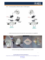
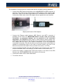
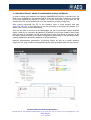
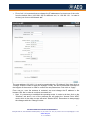
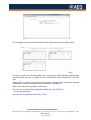
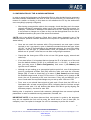
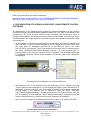
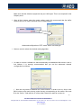
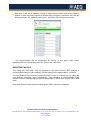
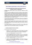
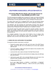
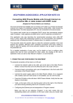
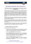
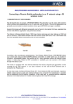
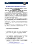
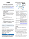
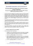
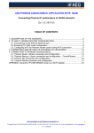
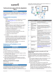
AUDIOCODECS AEQ PHOENIX. APPLICATION NOTE 4-B
Connecting two Phoenix Audiocodecs through a point-to-point IP
radio link operating in the 5 GHz band
Configuration of the units via remote control software
1. DESCRIPTION OF THE SCENARIO
Recently several manufacturers have started to offer digital radio links with IP connectivity
based on IEEE 802.11a, using extremely directive antennas that operate in a free RF band.
These links can be used to transport data between several locations, to join venues of a
same organization, or grant Internet access to places where ADSL is not available. The
main features of these products are long range, low power consumption and nice cost
effectiveness.
We can use them for bidirectional audio transport between two radio broadcast production
centers in a same town, or setting up a link between radio studio and transmitter (STL) or
between a remote location where some event is being held and the radio studio.
We have evaluated two solutions with different cost and performance ranges.
Ubiquity presents a wide range of systems with different performance levels and a very
adjusted price that operate under the same setup/operation software platform, called
AirOS v5, that is incorporated in the equipment as an embedded Web server. The IP
Nanobridge M 5G22 system has been tested, but the procedure followed is very similar to
tens of Ubiquity products that are configured the same way.
On the other hand, we have also selected for our tests a system from Alvarion, BreezeNet
B14. It is more costly, its configuration is less intuitive, but it is relatively capable without
direct line-of-sight, a characteristic that can make it very useful in some cases where other
equipments such as Ubiquity’s can’t establish a link.
There are some other European and North-American manufacturers, each one with its
own cost and functionality characteristics. But after the tests, we reached the conclusion
that most of them will be able to work more or less easily with one or several pairs of
Phoenix Audiocodecs in order to send one or more bidirectional audio programs.
In fact, the large bandwidth offered by this kind of products allows sending one or more
linear (uncompressed) audio channels through the same radio link (max. 2 stereo
channels when using Phoenix Studio or Venus).
2. REQUIRED HARDWARE
RS-1 Two AEQ Phoenix family professional audiocodecs. (Phoenix Studio, Mercury,
Venus, or a combination of them, even more than one pair)
RS-2 Two Ubiquity NanoBridge M 5G22, Alvarion BreezeNet B14 or similar antennas.
1
APLICACIONES ELECTRONICAS QUASAR S.A.
C/ Margarita Salas 24, 28919 LEGANÉS. MADRID (SPAIN) Tel.:(34) 91 686 13 00 * FAX: (34) 91 686 44 92 .E-mail: [email protected] . Web:
www.aeq.eu
N.I.F. :A-28620649
RS-3 Connecting cabling (4 Ethernet cables, 2 POE adapters).
Schematic of a radio STL setup based on AEQ Phoenix Mercury
3. INSTALLATION
Install one antenna at each of the ends of the communication to be established.
Front and rear images of the Ubiquity and Alvarion systems
2
APLICACIONES ELECTRONICAS QUASAR S.A.
C/ Margarita Salas 24, 28919 LEGANÉS. MADRID (SPAIN) Tel.:(34) 91 686 13 00 * FAX: (34) 91 686 44 92 .E-mail: [email protected] . Web:
www.aeq.eu
N.I.F. :A-28620649
The installation of each antenna is usually made with the included mounting hardware.
Connect the AEQ Phoenix audiocodec to the NANOBRIDGE M 5G22 antennas in
each end. The antennas are fed by means of POE adapters, which combine data
and power supply to the same RJ45 cable that is connected to the radio system.
Connect the mains cable to the POE adapter that is supplied with each antenna.
Ubiquity and Alvarion POE adapters
Connect the Ethernet cable between AEQ Phoenix (use NET1 connector if
possible) and the POE unit (IMPORTANT NOTE: use the “LAN” port for this
connection, or permanent damage can be produced to the connected
equipment). RECOMMENDATION: install a small Ethernet switch between the
audiocodec and the POE unit that will allow you to connect other equipments such
as a laptop that will help in the remote configuration of all the equipments
connected in this setup. This will also allow you to connect several audiocodecs as
needed for multichannel links). In the case of Phoenix Studio, only one of the
Ethernet connectors at the back of the unit needs to be used, (i.e. ETH1).
Connect an Ethernet cable from the POE adapter to the antenna back. Note that
this port is labelled “POE” in the Ubiquity unit and “Radio” in the Alvarion one.
Connect the analog or digital audio inputs and outputs in the back of the AEQ
Phoenix units. RECOMMENDATION: start with Ch1 for this test.
Connect the mains cords to each audiocodec.
Turn all the units on.
3
APLICACIONES ELECTRONICAS QUASAR S.A.
C/ Margarita Salas 24, 28919 LEGANÉS. MADRID (SPAIN) Tel.:(34) 91 686 13 00 * FAX: (34) 91 686 44 92 .E-mail: [email protected] . Web:
www.aeq.eu
N.I.F. :A-28620649
4. CONFIGURATION OF UBIQUITY NANOBRIDGE M 5G22 ANTENNAS.
In order to setup a link between two Ubiquity NANOBRIDGE M 5G22 or similar units, the
Web server embedded in the antenna itself is used. We must have a computer connected
to the each antenna, by means of a switch or a direct connection (in this case, we will
substitute the PC by the audiocodec once the antenna is properly configured)
After having connected the PC to the Antenna, open a Web browser and type
“http://192.168.1.20” in the URL bar (It may be necessary to configure the browser so it
doesn’t use a proxy for local addresses).
Once we are able to connect to the Nanobridge, we will be presented a small Windows
where it asks for an username & password. By default we must type “ubnt” in both fields.
After this step is completed, we will enter the main screen, that shows a summary of the
link status, present values for the basic configuration (depending on the operating mode),
network parameters and traffic statistics of all the interfaces.
Network administration parameters, monitoring utilities as well as a useful antennaalignment tool, ping, traceroute and speed tests are also accessible from the main screen.
4
APLICACIONES ELECTRONICAS QUASAR S.A.
C/ Margarita Salas 24, 28919 LEGANÉS. MADRID (SPAIN) Tel.:(34) 91 686 13 00 * FAX: (34) 91 686 44 92 .E-mail: [email protected] . Web:
www.aeq.eu
N.I.F. :A-28620649
•
First of all, it is important that we change the IP addresses of at least one of the units,
from the default value (192.168.1.20) to a different one, i.e. 192.168.1.21. In order to
do that, just click on the Network tab:
The new address (192.168.1.21) must be typed inside the “IP Address” field. Next click on
“Change” button in order to apply the changes. Finally, we will be presented a window on
the top part of the screen in order to confirm the new parameters. Just click on “Apply”.
From now on, once the antenna is restarted, we must change the IP address in the
browser URL bar in order to continue connected to it.
•
Next, it is necessary to establish the operating mode. In order to do that, click on the
“Wireless” tab and in one of the antennas we will select the “Access Point WDS”
mode, while in the other one we will select “Station WDS”. Remember to always apply
the changes with the “Change” button.
5
APLICACIONES ELECTRONICAS QUASAR S.A.
C/ Margarita Salas 24, 28919 LEGANÉS. MADRID (SPAIN) Tel.:(34) 91 686 13 00 * FAX: (34) 91 686 44 92 .E-mail: [email protected] . Web:
www.aeq.eu
N.I.F. :A-28620649
•
We also need to select the antenna physical type: please select “300 – 22 dBi” from
the list that is shown besides the text “Antenna”.
From now on we should start getting received signal in both ends of the communications;
this can be seen in the main screen.
We can align the antennas using the information in this page (particularly with the “Signal
Strength” information) in order to attain the strongest possible signal.
Please note that the, the better aligned the antennas are, the higher value of Signal
Strength we will get. We can also use the Antenna Alignment utility in the tools menu:
6
APLICACIONES ELECTRONICAS QUASAR S.A.
C/ Margarita Salas 24, 28919 LEGANÉS. MADRID (SPAIN) Tel.:(34) 91 686 13 00 * FAX: (34) 91 686 44 92 .E-mail: [email protected] . Web:
www.aeq.eu
N.I.F. :A-28620649
The management window shows statistics of the transmitted and received IP traffic:
In order to monitor the received signal level, connecting to both antennas, aligning them
and monitoring only one is enough, as the received level will be equivalent in the other
end.
Nothing else is required to connect both antennas, although there are several optional
parameters in order to establish security parameters, firewalls, etc.
Refer to the manual to get deeper information:
http://dl.ubnt.com/guides/nanobridge/NanoBridge_M2_M5_QSG.pdf
…or use the User guide:
http://dl.ubnt.com/guides/airOS/airOS_UG.pdf
7
APLICACIONES ELECTRONICAS QUASAR S.A.
C/ Margarita Salas 24, 28919 LEGANÉS. MADRID (SPAIN) Tel.:(34) 91 686 13 00 * FAX: (34) 91 686 44 92 .E-mail: [email protected] . Web:
www.aeq.eu
N.I.F. :A-28620649
5. CONFIGURATION OF THE ALVARION ANTENNAS
In order to setup the link between two BreezeNet B14 (or other similar Alvarion antennas)
the telnet interface embedded in the units is used. We must have a PC connected to it, by
means of a switch or directly (in this case we will substitute the PC by the audiocodec
once everything’s properly configured)
•
After having connected the cable to the computer, check that they are in the same
network and that IP connectivity exists (use a Ping command for this purpose, for
example). The default IP address of the antenna is 10.0.0.1, although once more it
is convenient to change one of then so they can be distinguished once the link is
established and they are part of the same local network.
*NOTE: this is the default IP address. Check that it hasn’t been changed in any of the
antennas before (because different addresses are required to operate the radio link, as
stated above).
•
Once we can reach the antenna with a Ping command, we must open a telnet
terminal to set it up properly: open a windows command window and type “telnet
10.0.0.1” (or the IP corresponding to the particular antenna). An user level will be
asked for. We will type “3” (Administrator). Next, the password is required. The
default one is “private”. After that, we can start configuring the antenna.
•
Check that the three green LEDs in the unit are ON (power supply, network and
radio link).
•
If not done before, it is important that we change the IP of at least one of the ends
from the default address (10.0.0.1) to a different one, i.e: 10.0.0.2. In order to do
that, just enter menu 3 (Basic Configuration), then menu 1 (IP Address) and
type the new IP address.
•
Although we are setting up a symmetrical point-to-point link, one of the antennas
must be configured as Base Unit (BU) while the other one must be a Remote
Bridge (RB). In order to check that, go to menu 2 (Unit Control) and test what’s
the available target mode in item D of the menu. If it allows you to change to RB
mode, the unit is presently a BU, and vice-versa. If they are not different, go to
menu 2 and make the required changes so you end up with 1 BU and 1 RB.
•
From now on we should have signal at both ends. Check that the LED bar is
illuminated with, at least, several green LEDs, indicating that the link has enough
signal to noise ratio. You will observe that better S/N ratio is got by aligning the
antennas properly. Just look for max. S/N.
Nothing else is required to connect both antennas, although there are several optional
parameters in order to establish security parameters, firewalls, etc.
IMPORTANT NOTE: it has been observed that, once power is cycled to the antennas,
they will not establish the link until we enter the telnet menu of one of them (BU, for
example), even if no option is changed. So a PC is necessary to put the link to work.
8
APLICACIONES ELECTRONICAS QUASAR S.A.
C/ Margarita Salas 24, 28919 LEGANÉS. MADRID (SPAIN) Tel.:(34) 91 686 13 00 * FAX: (34) 91 686 44 92 .E-mail: [email protected] . Web:
www.aeq.eu
N.I.F. :A-28620649
Refer to the manual to get deeper information:
http://www.intelek.cz/db/repository.nsf/v/E1B3DBF8B18B1D48C12576CD00442889/$file/
Manual_Alvarion_breezenet_B_6.0_system_manual.pdf
6. CONFIGURATION OF PHOENIX AUDIOCODEC USING REMOTE CONTROL
SOFTWARE
All audiocodecs in the Phoenix family (except for Phoenix Portable) can be remotely
controlled through ControlPHOENIX software installed on a PC that is connected to the
equipment by IP. Once we have access to the equipment, the first thing to do is to
configure its IP address. When we connect the Phoenix to a network, we must have a free
IP address within the range allowed in that local network. This network must be the same
in the antenna.
As an example, if the Ubiquity antennas have IP addresses 192.168.1.20 (default one)
and 192.168.1.21 (after we have changed it), we can assign the Phoenix codec (and
the used PCs) IP addresses 192.168.1.22 & 192.168.1.23, with a net mask
255.255.255.0, for example. The IP and mask of the Phoenix unit is configured under
the menu “SYSTEM->SETTINGS->Ethernet Settings”, for each physical port. In
Phoenix Studio, only one port is needed, ETH1 for instance. The IP address and mask
is configured using the remote control software, in Ethernet menu under equipment
configuration:
Accessing the IP configuration of a Phoenix Mercury
With Alvarion units, if the antennas have the addresses 10.0.0.1 (default one) and
10.0.0.2 (alter we have changed it), we can assign the Phoenix (and involved PCs) IP
addresses 10.0.0.3 & 10.0.0.4, with a net mask 255.255.0.0, for example. Again, the
IP and mask of the Phoenix unit is configured under the menu “SYSTEM>SETTINGS->Ethernet Settings”, for each physical port. For Phoenix Studio, only one
port is needed, ETH1 for instance. The IP address and mask is configured using the
remote control software, in Ethernet menu under equipment configuration
Next, we must configure the selected audio channel to work in IP mode, “RTP Raw”.
9
APLICACIONES ELECTRONICAS QUASAR S.A.
C/ Margarita Salas 24, 28919 LEGANÉS. MADRID (SPAIN) Tel.:(34) 91 686 13 00 * FAX: (34) 91 686 44 92 .E-mail: [email protected] . Web:
www.aeq.eu
N.I.F. :A-28620649
Make sure that the Alvarion equipment has port 1024 open. This is not required for the
Ubiquity units.
After all this is done, select the audio coding mode. We recommend that the buffer
mode is set as FIX, with a minimum size of around 40ms.
Advanced configuration of RTP mode: buffer size and type
Next we need to select the desired coding algorithm:
In order to ensure a reliable link that automatically re-establishes after electric cuts or
link failures, it is strongly recommended that you set the advanced channel
configuration as follows:
Now we only need to establish the communication. In order to do so, click on the
CALL button at the main remote control screen corresponding to this codec. We must
fill in the “Call to:” field with the IP of the other Phoenix we want to connect to.
10
APLICACIONES ELECTRONICAS QUASAR S.A.
C/ Margarita Salas 24, 28919 LEGANÉS. MADRID (SPAIN) Tel.:(34) 91 686 13 00 * FAX: (34) 91 686 44 92 .E-mail: [email protected] . Web:
www.aeq.eu
N.I.F. :A-28620649
Note that, if only the IP address is filled in, audio stream will be sent to port 1024 by
default. In case we need to specify a different port, just type it in the same line, with the
following format: <IP_address>:<dest_port>, as shown in the following example::
The communication will be established by clicking on the green CALL button
(assuming that we have already done the same in the other end)
IMPORTANT NOTICE:
This setup and THE CALL must be repeated in the other Phoenix (RTP protocol is
connection-oriented, not call-oriented). Use the same audio coding scheme, of course.
You can establish the connection using SIP DIRECT mode in a similar way, by calling the
units with the convention name <user>@<IP>. This procedure is further detailed in the
relevant Phoenix User Manual and has the advantage of avoiding the need to call in both
ends.
Once both Phoenix show synchronization (green LED), the link is completed.
11
APLICACIONES ELECTRONICAS QUASAR S.A.
C/ Margarita Salas 24, 28919 LEGANÉS. MADRID (SPAIN) Tel.:(34) 91 686 13 00 * FAX: (34) 91 686 44 92 .E-mail: [email protected] . Web:
www.aeq.eu
N.I.F. :A-28620649