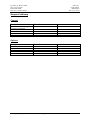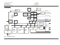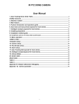
1
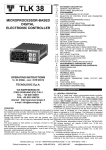
HARDWARE MANUAL
OAK_EMUF
Revision 2.03
Status: V2 released
W. Bals
Ing. Büro W. Kanis GmbH
file: hb_ges_hw_v2_03_020528.doc
page
Ortsteil Traubing,
Brückenweg 2, D 82327 Tutzing
Tel. 08157/9355-0, Fax 08157/9355-29
Internet http://www.kanis.de
Ing. Büro W. Kanis GmbH
http://www.kanis.de
BALS HW & SW
http://www.werner-bals.de
Power-PC
OAK_EMUF
HW Manual
Rev. 2.03 05.02
Edition history
Date
Changes
Name
981125
Transferred from version
1_00
Released V1.10
Relaesed V2.00
WB
990703
010225
011124
020407
020528
Preliminary V2.01
Corrections from KANIS
Add Configuration
Informations
file: hb_ges_hw_v2_03_020528.doc
WKANIS
WB
WB
WB
WB
page 2
Comment
Header...
Transferred from
OAK_EMUF
NV-RAM
Reset Configuration
Ing. Büro W. Kanis GmbH
http://www.kanis.de
BALS HW & SW
http://www.werner-bals.de
Power-PC
OAK_EMUF
HW Manual
Rev. 2.03 05.02
Table of Contents
Edition history ......................................................................................................................................................... 2
Table of Contents .................................................................................................................................................... 3
Tables and figures: .............................................................................................................................................. 3
Preface and Warnings.............................................................................................................................................. 4
Preface ................................................................................................................................................................. 4
Warning ............................................................................................................................................................... 4
Scope of delivery..................................................................................................................................................... 5
Content: ............................................................................................................................................................... 5
Options: ............................................................................................................................................................... 5
General description.................................................................................................................................................. 6
General ................................................................................................................................................................ 6
Block-Diagram .................................................................................................................................................... 7
RAM / ROM........................................................................................................................................................ 8
Inputs / Outputs ................................................................................................................................................... 8
MPC555 Onboard Peripherals............................................................................................................................. 8
SMC9432 Ethernet .............................................................................................................................................. 8
Realtime-Clock.................................................................................................................................................... 9
NV-RAM............................................................................................................................................................. 9
Power Supply ...................................................................................................................................................... 9
Installation ............................................................................................................................................................. 10
Connectors............................................................................................................................................................. 11
Connector locations ........................................................................................................................................... 11
Power Connector ST06...................................................................................................................................... 11
CAN .................................................................................................................................................................. 11
Serial, ST02 ....................................................................................................................................................... 11
Ethernet ............................................................................................................................................................. 12
BNC............................................................................................................................................................... 12
Twisted Pair................................................................................................................................................... 12
BASE-Connector ST01 ..................................................................................................................................... 13
Diagnostic, ST05 ............................................................................................................................................... 14
Jumpers and Switches............................................................................................................................................ 14
Jumper locations................................................................................................................................................ 14
J01..J04, RESET-Configuration ........................................................................................................................ 14
J07..J08, Test Power Supply.............................................................................................................................. 14
Address Range....................................................................................................................................................... 15
Interrupts ............................................................................................................................................................... 16
Local interrupt sources ...................................................................................................................................... 16
External interrupt sources.................................................................................................................................. 16
Mechanical Specification ...................................................................................................................................... 17
Expansions............................................................................................................................................................. 17
Related Documents:............................................................................................................................................... 17
Tables and figures:
Figure 1, Blockdiagram complete ........................................................................................................................... 7
figure 2, address range........................................................................................................................................... 15
file: hb_ges_hw_v2_03_020528.doc
page 3
Ing. Büro W. Kanis GmbH
http://www.kanis.de
BALS HW & SW
http://www.werner-bals.de
Power-PC
OAK_EMUF
HW Manual
Rev. 2.03 05.02
Preface and Warnings
Preface
© 2000/2002 Ing. Büro W.KANIS GmbH and BALS HW & SW
The information in this document has been carefully checked and is believed to be entirely reliable. However, no
more responsibility is assumed for inaccuracies. Furthermore, KANIS reserves the right to make changes to any
products herein to improve reliability, function or design. KANIS does not assume any liability arising out of the
application or use of any product or circuit described herein; neither does it convey any license under is patent
rights or the rights of others.
This document contains copyrighted information. All rights including those of translation, reprint, broadcasting,
photomechanical or similar reproduction and storage or processing in computer systems, in whole or part, are
reserved.
This document is edited and printed by:
Ing. Büro W.KANIS GmbH
Brückenweg 2
D82327 Traubing
Telephone:
+49 8157 93550
Fax:
+49 8157 9355-29
W.B.
Warning
This equipment generates, uses and can radiate radio frequency energy and, if not installed and used in
accordance with the manual, may cause interference to radio communications.
file: hb_ges_hw_v2_03_020528.doc
page 4
Ing. Büro W. Kanis GmbH
http://www.kanis.de
BALS HW & SW
http://www.werner-bals.de
Power-PC
OAK_EMUF
HW Manual
Rev. 2.03 05.02
Scope of delivery
Content:
Description
Order No.
Hardware, Freeware OAK_EMUF
2MB RAM, 4MB ROM
Tbd.
comments
Options:
Description
Order No.
Native Software
OS-9 BSP Software
Complete Development Tools
SFT-99959-000
SFT-99958-000
SFT-99964-000
file: hb_ges_hw_v2_03_020528.doc
comments
page 5
Ing. Büro W. Kanis GmbH
http://www.kanis.de
BALS HW & SW
http://www.werner-bals.de
Power-PC
OAK_EMUF
HW Manual
Rev. 2.03 05.02
General description
General
The OAK_EMUF Board is a single Euro-format board with Motorola Power-PC 555 Processor. The main
features are:
♦ POWER PC CPU from Motorola (40 MIPS)
32 32bit integer., 32 64bit floating point register
incl. I/O, Timer, Counter, IRQ-handling
incl. Chipselect
♦ Single Europe Board
♦ 1 to 4 MB Burst-Ram (0 Wait States,2-1-1-1 burst cycle)
♦ up to 8 MB Flash Eprom
♦ CAN interface
♦ Ethernet interface
♦ I/O-expansion bus
This Board is based on the very popular Power-PC Processor family of Motorola. The On-Board 555-Prozessor
includes Chipselect,, Timer, Counter and IRQ-Management. In Addition to the great integer performance a
floating-point unit is included. The Processor runs at 40Mhz. Speed can be changed by software and increased, if
faster versions will be available.
The Design with fast synchronous BURST-Rams guaranties a overall bigger performance also with larger
programs.
Most of the input/output-features are built around former 68376-IO-interfaces, which is avalibale on the
MPC555 as a peripheral chip. This brings the full use of all of the well known I/O-features of the 68376 together
with the calculating power of the MPC555.
The high-speed input/output is driven by an SMC-Ethernet-Chip 9432 and supports BNC and Twisted-pair
interfaces.
The I/O-structure helps also to start with this board with the same software as later used in MPC55x-Prozessorversions.
Debug can be done completely over BDM-interface to MPC555 processor.
file: hb_ges_hw_v2_03_020528.doc
page 6
Ing. Büro W. Kanis GmbH
http://www.kanis.de
BALS HW & SW
http://www.werner-bals.de
Power-PC
OAK_EMUF
HW Manual
Rev. 2.03 05.02
Block-Diagram
Clockgenerator
Analog In
Timer
Watchdog
QSPI
seriell
QSM
seriell
16*
Timer
TPU2
16*
Timer
Timer Interface
digital
Input /
Output
Digital I/O
QADC
QADC
16*anal. 16*anal.
TPU2
Input
Input
CPU
Power PC
55x
debug
Interface
RTC
+
STBY-RAM
Temper.
input
CTM4
9*Timer
CS
Addr.
Data
TOUCAN1
TOUCAN1
V24
level conv.
Data Bus
Seriell
EEPROM
Data Bus D31~D0
RESET
Logik
power
suppl.
CAN
level conv.
Power supply
5V
3,3V
BURSTRAM
1-4MB
FLASH-ROM
2-8MB
Line In
8...26V
Figure 1, Blockdiagram complete
file: hb_ges_hw_v2_03_020528.doc
page 7
NVRAM
32K
CAN
level conv.
Rs232 Interface
SMC
Ethernet
level
converter
BNC
TP
AUI
Ing. Büro W. Kanis GmbH
http://www.kanis.de
BALS HW & SW
http://www.werner-bals.de
Power-PC
OAK_EMUF
HW Manual
Rev. 2.03 05.02
RAM / ROM
The standard Version of OAK_EMUF comes with 4MB Burst Ram. The Burst RAM devices are synchronous SRAM’s
with 32bit width in/output and support a synchronous burst transfer with 2-1-1-1 burst cycle and. The burst rams are
connected to CS1 of MPC555 SIU and can be located to every address in the PowerPC address space.. For more details
look in description of BURST-Ram and also SIU of MPC555.
The Flash-ROM is built with standard flash devices 16bit devices. On OAK_EMUF the onboard flash is always 32bit
accessible to increase access speed. External flash is connected to CS0 of MPC555 SIU to enable booting out of this
flash.
NVRAM is connected to CS2 of the MPC555-SIU. NVRAM can only be accessed by 8bit transfer.
For the bus interface between 3V3 and 5V devices a bus-driver (IC13) is used.
Inputs / Outputs
The Input / Output of the OAK_EMUF can be separated in 3 groups:
♦ MPC555 Onboard-Peripherals like QSM, CAN, TPU, MIOS
♦ SMC 9432 Ethernet Controller
♦ CS3-connected external devices
MPC555 Onboard Peripherals
The OAK_EMUF uses MPC555 onboard peripherals. The base-address of all internal devices can be SW-controlled via
Base Address register.
The main I/O-features are:
- asynchronous serial interface (QSM)
- synchronous serial interface (QSPI)
- 10bit A/D-converter (QADC)
- 16 channel timer processor (TPU3)
- 16 I/O with special functions (MIOS)
- CAN interface (TOU-CAN)
SMC9432 Ethernet
The Ethernet-Interface is built around a SMC9432 Peripheral Controller. This Controller is directly connected to the
MPC555 with Chipselect CS3. The HW-Layer is realized as BNC, TP and AUI-Interface with all the related
specifications.
file: hb_ges_hw_v2_03_020528.doc
page 8
Ing. Büro W. Kanis GmbH
http://www.kanis.de
BALS HW & SW
http://www.werner-bals.de
Power-PC
OAK_EMUF
HW Manual
Rev. 2.03 05.02
Realtime-Clock
For Realtime-clock a Motorola MC68HC68 is used and connected to the QSPI-interface on 68376 peripherals with CS
PCS2.
NV-RAM
For non volatile memory for data an ZMD NV-Ram device is used and connected to the CS2. This device can only be
accessed by 8bit transfer.
Power Supply
The Power Supply is realized with switched regulated circuits. The input voltage can range from 7V...to 16V. All
onboard voltages are regulated, especially 3,3V for MPC50x and BURST-SRAM’s and 5V for all other peripherals.
The complete board needs maximum 7W, so the power supply input current is about 0.5A at 14V input voltage.
file: hb_ges_hw_v2_03_020528.doc
page 9
Ing. Büro W. Kanis GmbH
http://www.kanis.de
BALS HW & SW
http://www.werner-bals.de
Power-PC
OAK_EMUF
HW Manual
Rev. 2.03 05.02
Installation
The installation of the OAK_EMUF is very easy. The power supply must meet the specification described in the chapter
„General description, power supply“.
The serial RS232 interface can be used to connect a serial terminal or a standard serial interface from PC. The standard
SW on board configures this interface with:
- 9600 baud
- no parity check
- eight data bits
- one stop bit
These specifications can only be changed by software.
For the pin-assignment of the RS232 connector see chapter „connectors, serial“ .
If the board is supplied with OS9®, then the twisted-pair interface can also be connected and used for communication.
Communication parameters on TCP/IP can only be changed by software.
file: hb_ges_hw_v2_03_020528.doc
page 10
Ing. Büro W. Kanis GmbH
http://www.kanis.de
BALS HW & SW
http://www.werner-bals.de
Power-PC
OAK_EMUF
HW Manual
Rev. 2.03 05.02
Connectors
OAK_EMUF has two different ways to be used in industrial environment:
- in a multiboard-environment over backplane with connector
- in a single board environment with power supplied over ST06.
The complete processor peripheral lines are available on connector ST07 and ST08 also as on ST02.
Connector locations
See HW-Documenation of KANIS
Power Connector ST06
This connector only has two lines (+, GND). In a single board environment this connector is used to supply power to
OAK_EMUF.
CAN
CAN is available on both of the expansion connectors. CAN is provided with a standard automotive interface built
around a Phillips 82C251 Interface.
CAN is connected on ST01, pin B29 and B28.
Serial, ST02
The serial interface is built on a standard 9 pin SUB-D-connector.
Pin
1
2
3
4
5
6
7
8
9
Direction
Out
In
Out
In
Signal
Description
NC
TxD
RxD
NC
GND
NC
Reserved
NC
Reserved
Not connected
Transmit Data
Receive Data
Not connected
Ground
Not connected
file: hb_ges_hw_v2_03_020528.doc
Not connected
page 11
Ing. Büro W. Kanis GmbH
http://www.kanis.de
BALS HW & SW
http://www.werner-bals.de
Power-PC
OAK_EMUF
HW Manual
Rev. 2.03 05.02
Ethernet
BNC
BNC is not available in current OAKMEUF-versions.
Twisted Pair
The Twisted Pair interface is built at connector ST03.
Pin
1
2
3
4
5
6
7
8
Direction
Signal
Description
ETXP
ETXN
ERXP
ERXN
file: hb_ges_hw_v2_03_020528.doc
page 12
Ing. Büro W. Kanis GmbH
http://www.kanis.de
BALS HW & SW
http://www.werner-bals.de
Power-PC
OAK_EMUF
HW Manual
Rev. 2.03 05.02
BASE-Connector ST01
Base-Connector ST01 is used, if OAK_EMUF is mounted in a rack with backplane. All Signals are fed on this
connector except Ethernet-connections.( see also HW-Documentation)
Pin
Direct. Signal
row A
Description
Pin
row
B
Direct.
Signal
Description
Pin
row
C
Direct.
Signal
Description
1
2
3
4
5
6
7
8
9
10
11
12
13
14
15
16
17
18
19
20
21
22
23
24
25
26
27
28
29
30
31
32
1
2
3
4
5
6
7
8
9
10
11
12
13
14
15
16
17
18
19
20
21
22
23
24
25
26
27
28
29
30
31
32
An. In.
An. In.
An. In.
An. In.
An. In.
Dig. Out
An. In.
Dig. In
Dig. IO
Dig. IO
Dig. IO
Dig. In
Dig. IO
AN56I
AN57I
AN55I
AN50I
AN3I
PC5
AN2I
T2CLK
TPUCH12
TPUCH10
MISO
SCK
CDT10
TMS3
CTD3
CTD4
PWM8
TPUCH0
TPUCH2
TPUCH4
TPUCH7
n.c.
n.c.
n.c.
n.c.
n.c.
n.c.
CAN_H
CAN_L
VPLS
VPLS
GND
1
2
3
4
5
6
7
8
9
10
11
12
13
14
15
16
17
18
19
20
21
22
23
24
25
26
27
28
29
30
31
32
An. In.
An. In.
An. In.
An. In.
Dig. Out
Dig. Out
An.In.
Dig. IO
Dig. IO
Power
Dig. IO
Dig. IO
Dig. In
Dig. IO
Dig. IO
Dig. IO
Dig. IO
Dig. In
Dig. IO
Power
Dig. IO
Dig. IO
AN54I
AN53I
AN52I
AN49I
PC4
PC6
AN0I
TPUCH15
TPUCH13
VSTBY
TPUCH6
PCS0
MOSI
TRST
PCS3
CTM2C
PWM6
TDI
CTD9
GND
PCS1
TPUCH8
n.c.
n.c.
+12V (Supply In)
IRQ1_376
IRQ1_376
IRQ1_376
IRQ1_376
IRQ1_376
VCC
GND
An. In.
An. In.
An. In.
An. In.
An. In.
Dig. Out
In
Out
Dig. IO
Dig. IO
Dig. IO
Dig. IO
Dig. Out
Dig. Out
Dig. Out
Dig. Out
Power
Dig. IO
Dig. Out
Dig. IO
Power
Power
AN58I
AN59I
AN51I
AN48I
AN1I
UHR CLK
PC3
VREF
TPUCH14
TPUCH11
TPUCH5
TPUCH1
PCS2
PWM5
PWM7
TCK
+U
TPUCH13
TDO
TPUCH9
n.c.
n.c.
n.c.
n.c.
n.c.
n.c.
n.c.
n.c.
n.c.
n.c.
VCC
GND
file: hb_ges_hw_v2_03_020528.doc
Dig. IO
Dig. IO
Dig. IO
Dig. IO
.
CAN
CAN
Power
page 13
Power
Dig. In
Dig. In
Dig. In
Dig. In
Dig. In
Power
Power
Ing. Büro W. Kanis GmbH
http://www.kanis.de
BALS HW & SW
http://www.werner-bals.de
Power-PC
OAK_EMUF
HW Manual
Rev. 2.03 05.02
Diagnostic, ST05
The Diagnostic-Connector is a standard BDM ( Background-Debug-Mode) – Connector for Motorola –
Processor Debug Interface. On this connector customer can connect BDM-Interfaces (for example. EBDI-Lite..)
Connection of BDM-Interface has to be carefully checked on
orientation ( no mark for Pin 1) !
Pin
Direction
Signal
Description
1
2
3
4
5
6
7
8
9
10
Dig.In
Dig.Out
Power
Dig. In
Power
Dig. In
Dig. In
Dig. In
Power
Dig. Out
VFLSO
RESETOUT
GND
DSCK
GND
VFLS1
RESETIN
DSDI
3V3
DSDO
Look at rcpurm.pdf on OAK_EMUF-CD
Jumpers and Switches
The following figure shows position of all jumpers on the OAK_EMUF Board. A description of all jumpers
follows.
Jumper locations
Look in HW-documentation.
J01..J04, RESET-Configuration
The RESET-Configuration Word of the MPC555 Processor is driven by 74LV244 (IC10) and is controlled by
Jumper/Resistor R116…R112.
Resistor
R116
R115
R114
R113
R112
Databus
line
MPC555
Default
Reset Configuration Word Remark
configuration
D1
D3
D19
D20
D28
For more details of the RESET-Configuration see MPC555-user manual.
J07..J08, Test Power Supply
During Test of Power Supply J07 and J08 are temporarily used in Position „B“. For Standard use J07 and J08
must always set to position A.
file: hb_ges_hw_v2_03_020528.doc
page 14
Ing. Büro W. Kanis GmbH
http://www.kanis.de
BALS HW & SW
http://www.werner-bals.de
Power-PC
OAK_EMUF
HW Manual
Rev. 2.03 05.02
Address Range
The OAK_EMUF uses the complete 4GB address range of the MPC555 processor. All external devices are
software programmable in the start address, so the figure shown below only gives an example.
For detailed information look in the SW-Manual for OAK_EMUF standard software or in the Board-supportpackage-description of OS-9 for OAK_EMUF.
This is the recommended default configuration. All addresses are SW-configurable.
Start
address
End
address
Description
Comment
0x0000 0000
0x0020 0000
0x0040 0000
0x001f ffff
0x003f ffff
0x007f ffff
First ram Bank
Second ram bank
Burst ram for code and data, prog. CS1
Burst ram for code and data, prog. CS2
Reserved for 8M ram version
0x0080 0000
0x00ff ffff
Free
0x0100 0000
0x01ff ffff
MPC555 Onboard peripherals
And internal flash
Selected by Base register
See MPC555 documentation
0xb000 0000
0xb020 0000
0xb040 0000
0xb060 0000
0xb080 0000
0xb0a0 0000
0xb0c0 0000
0xb0e0 0000
0xb001 ffff
0xb003 ffff
0xb005 ffff
0xb007 ffff
0xb009 ffff
0xb00 ffff
0xb00f ffff
0xb0f ffff
SMC9432
CS3_1
CS3_1
CS3_1
CS3_1
CS3_1
CS3_1
CS3_1
Programmable address on CS3
Sub cs on CS3 decoder
Sub cs on CS3 decoder
Sub cs on CS3 decoder
Sub cs on CS3 decoder
Sub cs on CS3 decoder
Sub cs on CS3 decoder
Sub cs on CS3 decoder
0xc000 0000
0xc000 7fff
32K NV-RAM
0xd000 0000
0xefff ffff
Free
0xfe00 0000
0xff00 0000
0xfeff ffff
0xffff ffff
Flash EPROM
Flash EPROM
External flash, 1st Megabyte
External flash Boot area, if external boot is
used in configuration
figure 2, address range
file: hb_ges_hw_v2_03_020528.doc
page 15
Ing. Büro W. Kanis GmbH
http://www.kanis.de
BALS HW & SW
http://www.werner-bals.de
Power-PC
OAK_EMUF
HW Manual
Rev. 2.03 05.02
Interrupts
The MPC555 has external interrupt request lines called IRQ0...IRQ6. ( see also application node AN1281/D or
related document in the OAK_EMUF documentation AN1281_D.pdf). Some of these lines are used for
peripherals on the OAK_EMUF.
Local interrupt sources
IRQ
line
Description
IRQ3
SMC Ethernet controller
Comment
External interrupt sources
All information are customer dependant, all lines are connected to external connector ST08.
IRQ
line
Description
IRQ0
IRQ1
IRQ2
IRQ4
IRQ5
IRQ6
file: hb_ges_hw_v2_03_020528.doc
Comment
PPIRQ0
PPIRQ2
PPIRQ3
PPIRQ4
PPIRQ5
PPIRQ6
page 16
Ing. Büro W. Kanis GmbH
http://www.kanis.de
BALS HW & SW
http://www.werner-bals.de
Power-PC
OAK_EMUF
HW Manual
Rev. 2.03 05.02
Mechanical Specification
The board is a standard single-Euro-format ( 160*100 mm).
The exact OAK_EMUF size over all is 192*160 mm. Maximum height is 22 mm.
Expansions
Every customer requested expansion board can be designed and manufactured by KANIS.
Related Documents:
OAK_EMUF-V1_10_komplett.pdf
HW-Documentation
Datasheets, Manuals, Technical Summaries
--------------------------------------------------------------------------MPC555um.pdf
MPC555 user manual
74FCT164245.pdf
74FCT164245 Datasheet
74LS244.pdf
74LS244 Datasheet
74LV244.pdf
74LV244 Datasheet
91C94.pdf
91C94 Datasheet
AM29F800.pdf
AM29F800 Datasheet
an1236.pdf
Timing Performance of TPU I/O Hardware
an1281_d.pdf
MCP505 Interrupts
AT24640.pdf
AT24640 Datasheet
DS1305_tss.pdf
DS1305 real time clock Datasheet
DP8392.pdf
DP8392A Datasheet
gptrm.pdf
GPT Reference Manual
Mach211.pdf
MACH211 Datasheet
Mach211SP.pdf
MACH211SP Datasheet
Max1626.pdf
MAX1626 Datasheet
Max233.pdf
MAX233 Datasheet
Max708.pdf
MAX708 Datasheet
PCA82C251.pdf
PCA82C251 Datasheet
rcpurm.pdf
RCPU RISC CPU Reference Man.
file: hb_ges_hw_v2_03_020528.doc
page 17