1
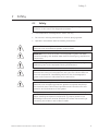
GE Healthcare
ÄKTAdesign
Reverse flow Kit
User Manual
ÄKTA™
Important user information
All users must read this entire manual to fully understand
the safe use of Reverse flow Kit.
WARNING!
The WARNING! sign highlights instructions that
must be followed to avoid personal injury. It is
important not to proceed until all stated conditions
are met and clearly understood.
CAUTION!
The Caution! sign highlights instructions that must
be followed to avoid damage to the product or
other equipment. It is important not to proceed
until all stated conditions are met and clearly
understood.
Note
The Note sign is used to indicate information
important for trouble-free and optimal use of the
product.
CE Certifying
This product meets the requirements of applicable CEdirectives. A copy of the corresponding Declaration of
Conformity is available on request.
The CE symbol and corresponding declaration of
conformity, is valid for the instrument when it is:
– used as a stand-alone unit, or
– connected to other CE-marked GE Healthcare
instruments, or
– connected to other products recommended or
described in this manual, and
– used in the same state as it was delivered from GE
Healthcare except for alterations described in this
manual.
Recycling
This symobl indicates that the waste of electrical
and electronic equipment must not be disposed
as unsorted municipal waste and must be
collected separately. Please contact an authorized
representative of the manufacturer for information
concerning the decommissioning of equipment.
WARNING!
This is a Class A product. In a domestic environment this
product may cause radio interference in which case the
user may be required to make adequate measures.
Contents
Contents
1 Introduction
1.1
1.2
General ................................................................................................... 7
Optional flow direction valve V7 ................................................ 7
2 Safety
2.1
Safety ...................................................................................................... 9
3 Unpacking
4 Pre-requisites
5 Mounting of brackets
5.1
5.2
Valve ID ................................................................................................ 16
UniNet Connection ......................................................................... 17
6 Installation
6.1
Preparation for use ....................................................................... 19
7 Operation
7
7.1
7.2
Preparing for operation ............................................................... 21
ÄKTAFPLC – UNICORN 3.2–3.21 .................................................. 22
7.2.1
Using the flow direction valve in a run .............................................. 22
7.3
ÄKTAFPLC – UNICORN 4.0–4.12 ............................................... 24
7.3.1
Using the flow direction valve in a run ............................................... 24
7.4
ÄKTApurifier/ÄKTAbasic – UNICORN 3.2–3.21 .................... 26
7.4.1
Using the flow direction function in a run ......................................... 26
7.5
ÄKTApurifier/ÄKTAbasic – UNICORN 4.0–4.11 ................... 28
7.5.1
Using the flow direction function in a method ............................... 28
7.6
ÄKTApurifier/ÄKTAbasic – UNICORN 4.12 ............................ 29
7.6.1
Using the flow direction function in a run ......................................... 29
7.7
ÄKTApurifier - UNICORN 5.10 .................................................... 30
7.7.1
Using the flow direction function in a run ......................................... 30
2
Reverse flow Kit User Manual 71-5029-22 Edition AC
5
Contents
6
Reverse flow Kit User Manual 71-5029-22 Edition AC
Introduction 1
1
Introduction
1.1
General
ÄKTAdesign standard system configurations can be changed to optional
configurations. This flexibility in ÄKTAdesign system strategies allows the
user to enhance already used purification methods and also to develop new,
more complex methods.
When optional equipment is connected to a standard chromatographic
system, new sets of instructions to control the optional equipment become
accessible for the user.
Optional configurations are selected, installed and put into operation by the
user. An optional configuration consists of both hardware components and
software instructions.
Optional configurations are monitored and controlled via methods run
by the UNICORN™ control system in the same way as ÄKTAdesign
standardsystem configurations.
1.2
Optional flow direction valve V7
Preferentially in affinity based protein purification, elution is carried out
in the reversed direction to sample application. This prevents strongly
bound substances, accumulated at the inlet side, from interacting with the
immobilized ligand throughout the column before elution, and a dilution
of the sample by eluting through the total column volume. Thus resulting
peaks are sharper, the substance elutes more concentrated, and reversed
elution speeds up the elution process.
Reverse flow Kit User Manual 71-5029-22 Edition AC
7
1 Introduction
17
2 6
34 5
Flow Direction
Valve (V7)
COND
UV
Flow restrictor
Column
On-line
filter
Mixer
Pump A
17
2 6
34 5
Pump B
Injection
Valve (V1)
8
7
1
2
6
345
W3
Sample loop
W2
Fraction
collector
(optional)
Outlet Valve (V4)
(ÄKTApurifier, ÄKTAbasic)
W1
F3
The optional flow direction valve V7 (code no. 18-1108-40) is available for:
8
•
ÄKTAFPLC™ with UNICORN Software 3.2 or higher
•
ÄKTApurifier™ with UNICORN Software 3.21 AA or higher
•
ÄKTAbasic™ with UNICORN Software 3.21 AA or higher
Reverse flow Kit User Manual 71-5029-22 Edition AC
Safety 2
2
Safety
2.1
Safety
IMPORTANT! ÄKTAdesign is intended for laboratory use only, not for
clinical or in vitro use, or for diagnostic purposes.
•
The components are designed for indoor use only.
•
Do not use in a dusty atmosphere or close to spraying water.
•
Operate in accordance with local safety instructions.
WARNING! When using hazardous chemicals, all suitable protective
measures, such as protective glasses, must be taken.
WARNING! Ensure that the entire chromatographic system has been
flushed thoroughly with distilled water before removing any capillaries or
components.
WARNING! Always disconnect the power supply before attempting to
replace any item on the equipment during maintenance.
WARNING! If there is a risk that large volumes of spilt liquid may
penetrate the casing of the equipment and come into contact with the
electrical components, immediately switch off the chromatographic
system and contact an authorized service technician.
WARNING! When using hazardous chemicals, take all suitable protective
measures, such as wearing protective glasses and gloves resistant to
the chemicals used. Follow local regulations and instructions for safe
operation and maintenance of the system.
CAUTION! Make sure that the ÄKTAdesign instrument is switched off
before installing the optional components. The mains power to the
ÄKTAdesign instrument must be switched OFF before disconnecting or
connecting the UniNet-1 and UniNet-2 cables.
Reverse flow Kit User Manual 71-5029-22 Edition AC
9
2 Safety
10
Reverse flow Kit User Manual 71-5029-22 Edition AC
Unpacking 3
3
Unpacking
Unpack the optional components and check against the supplied packing
list. Inspect the items for obvious damage that may have occurred during
transportation.
CAUTION! Read the following information carefully, as well as all the
additional instructions supplied with the components, to ensure that the
ÄKTAdesign optional equipment is installed correctly.
Reverse flow Kit User Manual 71-5029-22 Edition AC
11
3 Unpacking
12
Reverse flow Kit User Manual 71-5029-22 Edition AC
Pre-requisites 4
4
Pre-requisites
The general procedures for creating and editing methods are described in
the UNICORN User Manuals.
Note:
The system configuration delay volume must be recalculated and
reset when the standard configuration after the UV flow cell is
changed.
ÄKTAFPLC, ÄKTApurifier and ÄKTAbasic respectively must be installed and fully
tested before the optional components are installed. See the Installation
Guide for your ÄKTAdesign chromatography system.
WARNING! Ensure that the entire system has been flushed thoroughly
with distilled water before removing any capillaries or components.
CAUTION! Make sure that the ÄKTAdesign instrument is switched off
before installing the optional components. The mains power to the
ÄKTAdesign instrument must be switched OFF before disconnecting or
connecting the UniNet-1 and UniNet-2 cables.
Reverse flow Kit User Manual 71-5029-22 Edition AC
13
4 Pre-requisites
14
Reverse flow Kit User Manual 71-5029-22 Edition AC
Mounting of brackets 5
5
Mounting of brackets
CAUTION! Make sure that the ÄKTAdesign instrument is switched off
before installing the optional components. The mains power to the
ÄKTAdesign instrument must be switched OFF before disconnecting or
connecting the UniNet-1 and UniNet-2 cables.
Optional equipment can be mounted on the system. When selecting
mounting location for the optional equipment it is important to choose a
location which minimize the length of the capillaries used to connect the
optional components to the rest of the system.
Many components that are attached to the mounting rails uses a snap in
bracket. The bracket is supplied separately with the component and needs �
to be fitted as shown below before the component can be attached.
2. Fit the attached
mounting bracket with
the two screws
Inserting components
1. Loosen the
two screws
Removing components
Reverse flow Kit User Manual 71-5029-22 Edition AC
15
5 Mounting of brackets
5.1
Valve ID
3
INV-907
The flow direction valve has a unique ID code which identifies it to the
UNICORN control system at system start-up. This ID code should be checked
before installation.
The ID code for the flow direction valve and the corresponding instructions
used in UNICORN to control it are as follows:
ID code
Valve type
Instruction in UNICORN
7
INV-907
Valve7
Components are connected to the UNICORN control system using
eitherUniNet-1 or UniNet-2 cables*. Both the UniNet-1 and the UniNet-2
data communication chain in standard configuration is routed from the rear
of the system pump via their respective components to the last component
in the chain where it is terminated with a plug.
*Frac-920, Frac-950, A-900 and A-905 are connected via the UniNet-1 chain. All other optional
components are connected via the UniNet-2 chain.
Note:
16
When Pump P-960 is used, it is always installed as the last
component in the UniNet-2 chain. Since the pump has an internal
termination, no termination plug is needed.
Reverse flow Kit User Manual 71-5029-22 Edition AC
Mounting of brackets 5
5.2
UniNet Connection
Both the UniNet-1 and the UniNet-2 chain can be interrupted anywhere
between the system pump and the termination plug to interconnect the
optional components in the chain. The termination plug can be moved to
the last component (furthest away from the system pump), if motivated by
cable routing considerations.
WARNING! Only use mains cables delivered or approved by GE
Healthcare.
To PC
Controller board
UniNet-2
chain
Fraction
collector
PC running UNICORN
Termination
plug
UniNet-1
chain
Use the attached UniNet-2 cables to connect the valve to the UniNet-2
communication link. The valve can be connected anywhere between the
system pump and the termination plug.
WARNING! Do not block the rear panel of the system. The mains
power switch must always be easy to access.
Reverse flow Kit User Manual 71-5029-22 Edition AC
17
5 Mounting of brackets
18
Reverse flow Kit User Manual 71-5029-22 Edition AC
Installation 6
6
Installation
6.1
Preparation for use
To start your ÄKTAdesign optional configuration system:
1
Switch on the ÄKTAdesign instrument with the mains switch located at
the front left on the system base.
2
Check that the computer and printer are switched on.
3
Log in (see the instrument user manuals).
4
In UNICORN Main Menu/Manager, select Administration:System Setup.
5
Select System and then click Edit. Click Component....
6
From the Component list, select the optional flow direction valve you
have installed by checking the box or by clicking ADD.
7
Click OK twice and then Close.
8
Cut and mount the required PEEK capillaries. Use a capillary with the
correct i.d. as required by your system. The principle flow path through
the valve is shown below:
Reversed flow configuration
DOWNWARD FLOW, position 1
UPWARD FLOW, position 2
1
To UV
monitor
1
2
3
4
6
5
Stop plug
Reverse flow Kit User Manual 71-5029-22 Edition AC
Pump
7
Pump
7
2
To UV
monitor
3
4
6
5
Stop plug
19
6 Installation
20
Reverse flow Kit User Manual 71-5029-22 Edition AC
Operation 7
7
Operation
7.1
Preparing for operation
1
A connected valve is automatically recognised by UNICORN at system
start-up. Check that the added valve is indicated in the flow scheme in
UNICORN.
2
Verify that the valve is functioning properly by issuing manual
commands from UNICORN as follows:
•
In System Control, select Manual:FlowPath.
•
Select instruction Valve7 (ÄKTAFPLC), FlowDirection valve (ÄKTApurifier,
ÄKTAbasic).
•
Select and execute a new position for the valve. View the valve in the
flow scheme panel to confirm that the position change has occured.
Valve panel
Reverse flow Kit User Manual 71-5029-22 Edition AC
21
7 Operation
7.2
ÄKTAFPLC - UNICORN 3.2–3.21
7.2.1
Using the flow direction valve in a run
Flow direction valve instruction is designated Valve7 in the flow scheme and
Run Data panes. To use a valve in a method, proceed as follows:
22
1
In the Main Menu, select File:New:Method to create a new method.
Select System:, Technique:, Template: and For column:. Click OK.
2
Select View:Text instructions to display the text instruction editor.
Double-click on the instruction block where you want to add the general
Reverse flow Kit User Manual 71-5029-22 Edition AC
Operation 7
function valve instruction, e.g. Gradient_Elution. Highlight the elution
instruction below to insert the valve instruction.
Click here to define a
variable name for the
Click here to define a
instruction parameter
variable name for the
instruction parameter
3
Click the Flowpath radio button.
4
From the Instructions list, select valve Valve7. For this valve, only two
positions should be selected. Position 1 = Downflow, position 2 = Upflow.
5
Define a variable name for the instruction parameter, Valve7_pos. This
variable allows you to turn the position of the valve to the port you
want.
6
Click OK. The defined variable is inserted in the method.
7
Return to the Variables page by selecting View:Run setup to set the
variable Valve7_pos to the desired position.
Reverse flow Kit User Manual 71-5029-22 Edition AC
23
7 Operation
8
Save the method.
9
Repeat step x–y above to insert an instruction Valve7 position
1– Downflow. This instruction should be inserted in instruction block
Start_conditions. This will ensure the flow returns to the Downflow
position for the new purification run.
7.3
ÄKTAFPLC - UNICORN 4.0–4.12
7.3.1
Using the flow direction valve in a run
Flow direction valve instruction is designated Valve7 in the flow scheme and
Run Data panes.
To use a valve in a method, proceed as follows:
1
In the Main Menu, select File:Method Wizard and create a new method.
2
Select View:Text instructions to display the text instruction editor.
Double-click on the instruction block where you want to add the flow
direction valve instruction, e.g. Elution.
3
Highlight the elution instruction (Valve7) below to insert the valve
instruction.
4
Click the Flowpath radio button.
5
From the Instructions list, select valve Valve7. For this valve, only two
positions should be selected. Position 1 = Downflow, position 2 = Upflow.
Click here to define a
variable name for the
instruction parameter
24
Reverse flow Kit User Manual 71-5029-22 Edition AC
Operation 7
6
Define a variable name for the instruction parameter, e.g. Valve7_pos.
This variable allows you to turn the position of the valve to the port you
want.
7
Click OK. The defined variable is inserted in the method.
8
Return to the Variables page by selecting View:Run setup to set the
variable Valve7_pos to the desired position.
9
Save the method.
10 Repeat step x–y above to insert an instruction Valve7 position
1– Downflow. This instruction should be inserted in instruction block
Start_conditions. This will ensure the flow returns to the Downflow
position for the new purification run.
Reverse flow Kit User Manual 71-5029-22 Edition AC
25
7 Operation
7.4
ÄKTApurifier/ÄKTAbasic - UNICORN 3.2–3.21
7.4.1
Using the flow direction function in a run
The flow direction valve instruction is designated FlowDirection. To use the
valve in a method, do as follows:
1
In the Main Menu, select File:New:Method to create a new method.
Select System:, Technique:, Template: and For column:. Click OK.
2
Select View:Text instructions to display the text instruction editor.
Double-click on the instruction block where you want to add the flow
direction valve instruction, e.g. Elution. Highlight the elution instruction
to insert the valve instruction.
�����������������������
����������������������
���������������������
26
3
Click the Flowpath radio button.
4
From the Instructions list, select FlowDirection. The valve instruction
parameter Position allows you to change position for the flow direction
valve using parameters DownFlow and UpFlow.
Reverse flow Kit User Manual 71-5029-22 Edition AC
Operation 7
5
Define a variable name for the instruction parameter, e.g. FlowDirection.
This variable allows you to turn the position of the valve to the direction
you want.
6
Click OK. The defined variable is inserted in the method.
7
Return to the Variables page by selecting View:Run setup to set the
variable FlowDirection to the desired position.
8
Save the method.
9
Repeat step x–y above to insert an instruction FlowDirection – downflow.
This instruction should be inserted in instruction block Start_conditions.
This will ensure the flow returns to the Downflow position for the new
purification run.
Reverse flow Kit User Manual 71-5029-22 Edition AC
27
7 Operation
7.5
ÄKTApurifier/ÄKTAbasic - UNICORN 4.0–4.11
7.5.1
Using the flow direction function in a method
The flow direction valve instruction is designated FlowDirection in the flow
scheme. In the Run Data pane it is designated V7_FlowDir.
To use the flow direction valve in a method, do as follows:
1
In the Method Editor, select File:Method Wizard and create a new
method.
2
Select View:Text instructions to display the text instruction editor.
Double-click on the instruction block where you want to add the flow
direction valve instruction, e.g. Elution. Highlight the elution instruction
to insert the valve instruction.
�����������������������
����������������������
���������������������
28
3
Click the Flowpath radio button.
4
From the Instructions list, select FlowDirection. The valve instruction
parameter Position allows you to change position for the flow direction
valve using parameters DownFlow and UpFlow.
Reverse flow Kit User Manual 71-5029-22 Edition AC
Operation 7
5
Define a variable name for the instruction parameter, e.g. FlowDirection.
This variable allows you to turn the position of the valve to the direction
you want.
6
Click OK. The defined variable is inserted in the method.
7
Return to the Variables page by selecting View:Run setup to set the
variable FlowDirection to the desired position.
8
Save the method.
9
Repeat step x–y above to insert an instruction FlowDirection – downflow.
This instruction should be inserted in instruction block Start_conditions.
This will ensure the flow returns to the Downflow position for the new
purification run.
7.6
ÄKTApurifier/ÄKTAbasic - UNICORN 4.12
7.6.1
Using the flow direction function in a run
The flow direction valve instruction is designated FlowDirection in the flow
scheme. In the Run Data pane, it is designated V7_FlowDir.
To use the flow direction valve in a method:
1
In the Method Editor, select File:Method Wizard and start creating a
new method.
2
In the Elution dialog, select Segment Gradient Advanced under Elution
Technique.
3
Click OK twice.
4
Select DownFlow or UpFlow under Flow Direction.
5
Save the method when finished.
Reverse flow Kit User Manual 71-5029-22 Edition AC
29
7 Operation
7.7
ÄKTApurifier - UNICORN 5.10
7.7.1
Using the flow direction function in a run
The flow direction valve instruction is designated FlowDirection in the flow
scheme. In the Run Data pane, it is designated V7_FlowDir.
To use the flow direction valve in a method:
30
1
In the Method Editor, select File:Method Wizard and start creating a
new method.
2
In the Elution dialog, select Segment Gradient Advanced under Elution
Technique.
3
Select DownFlow or UpFlow under Flow Direction.
Reverse flow Kit User Manual 71-5029-22 Edition AC
Operation 7
4
Save the method when finished.
Reverse flow Kit User Manual 71-5029-22 Edition AC
31
www.gehealthcare.com/lifescience
GE Healthcare Bio-Sciences AB
Björkgatan 30
751 84 Uppsala
Sweden
Drop Design, ÄKTA, ÄKTAFPLC, ÄKTApurifier, ÄKTAbasic and UNICORN are
trademarks of GE Healthcare companies. GE, imagination at work and GE
monogram are trademarks of General Electric Company.
Microsoft and Windows are either trademarks or registered trademarks of
Microsoft Corporation in the United States and/or other countries.
All goods and services are sold subject to the terms and conditions of sale
of the company within GE Healthcare which supplies them. GE Healthcare
reserves the right, subject to any regulatory and contractual approval, if
required, to make changes in specifications and features shown herein, or
discontinue the product described at any time without notice or obligation.
Contact your local GE Healthcare representative for the most current
information.
© 2005 General Electric Company – All rights reserved.
GE Healthcare Bio-Sciences AB, a General Electric Company.
GE Healthcare Bio-Sciences AB
Björkgatan 30, SE-751 84 Uppsala, Sweden
GE Healthcare Europe GmbH
Munzinger Strasse 5, D-79111 Freiburg, Germany
GE Healthcare UK Ltd
Amersham Place, Little Chalfont, Buckinghamhire, HP7 9NA, UK
GE Healthcare Bio-Sciences Corp
800 Centennial Avenue, P.O. Box 1327, Piscataway, NJ 08855-1327, USA
GE Healthcare Bio-Sciences KK
Sanken Bldg. 3-25-1, Huakunincho, Shinjuku-ku, Tokyo 169-0073, Japan
Asia Pacific Tel: +852 2811 8693 Fax: +852 2811 5251 • Australasia Tel: + 61 2 9899 0999 Fax: +61 2 9899 7511 • Austria Tel: 01/57606-1619 Fax: 01/57606-1627 • Belgium Tel: 0800 73 888
Fax: 03 272 1637 • Canada Tel: 800 463 5800 Fax: 800 567 1008 • Central, East, & South East Europe Tel: +43 1 982 3826 Fax: +43 1 985 8327 • Denmark Tel: 45 16 2400 Fax: 45 16 2424 • Finland &
Baltics Tel: +358-(0)9-512 39 40 Fax: +358 (0)9 512 39 439 • France Tel: 01 69 35 67 00 Fax: 01 69 41 96 77 • Germany Tel: 0761/4903-490 Fax: 0761/4903-405 • Italy Tel: 02 27322 1 Fax: 02 27302
212 Japan Tel: +81 3 5331 9336 Fax: +81 3 5331 9370 • Latin America Tel: +55 11 3933 7300 Fax: +55 11 3933 7304 • Middle East & Africa Tel: +30 210 9600 687 Fax: +30 210 9600 693 • Netherlands
Tel: 0165 580 410 Fax: 0165 580 401 • Norway Tel: 815 65 555 Fax: 815 65 666 • Portugal Tel: 21 417 7035 Fax: 21 417 3184 • Russia & other C.I.S. & N.I.S Tel: +7 (095) 232 0250, 956 1137
Fax: +7 (095) 230 6377 • South East Asia Tel: 60 3 8024 2080 Fax: 60 3 8024 2090 • Spain Tel: 93 594 49 50 Fax: 93 594 49 55 • Sweden Tel: 018 612 1900 Fax: 018 612 1910 • Switzerland
Tel: 0848 8028 12 Fax: 0848 8028 13 • UK Tel: 0800 616928 Fax: 0800 616927 • USA Tel: 800 526 3593 Fax: 877 295 8102
imagination at work
User Manual 71-5029-22 AC 03/2006