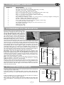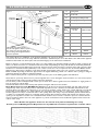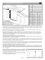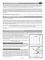
1
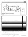
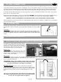
15.4 REMOVAL OF THE CONTROL BOX
GB IE
viously described in the relevant section. Remove the two securing screws and lift away the control box heatshield. Slide the
control box to the left off its mounting bracket, and remove the multiway connector from the rear.
Replacement is reverse of removal, taking care to ensure the box is mounted securely and each individual connector pin makes
good contact with the control box pin.
16.0 TROUBLESHOOTING GUIDE
Please note: Repair work to electrical appliances should only be carried out by a suitably qualified (qualified to City & Guilds 2392
[test and inspection] and City & Guilds 2382 [IEE 17th edition] for example) person in accordance with local and national safety
regulations.
WARNING : Repairs and other work by unqualified persons could be dangerous.
Technical description - modes of operation
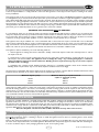
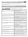
Fault/Problem
Cause/Remedy
There is no power to the control box
Check power at mains supply, check fuses
Check wall switch is turned ON
Fan fails to start and no neon indicator light on the control box
Check all plugs, connectors and continuity of wiring from mains supply
illuminates.
to control box (see figure 29 terminals 9 &10). If mains power is definitely present at the control box but neon indicator light does not light
AT ALL, even momentarily, then replace the control box.
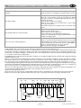
Check all plugs, connectors and continuity of wiring from terminals 6
& 8 on the control box (see figure 29) to terminals of the motor coil on
Fan fails to start and neon indicator light remains illuminated the fan. If this is all OK, check continuity across fan motor terminals, if
indefinitely without holding the ‘on’ button in (neon indicator OK, switch mains power on and press ‘on’ button, (indicator light
only extinguishes when you press the ‘off’ button).
remains illuminated). Check 240V is present at terminal 6 of the
control box (see figure 29) and at the live terminal of the fan motor.
If fan does not turn, replace fan.
Check all plugs, connectors and continuity of wiring from terminals 1,
Fan fails to start and neon indicator light is illuminated but only 2 & 3 on the control box (see figure 29) to the three terminals of the
when holding the ‘on’ button in.
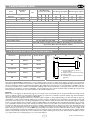
pressure switch. Check the pressure switch terminals are wired correctly (see figure 27). If all OK then replace pressure switch.
Check fan outlet for obstruction. Ensure silicone sensing pipes
and properly fitted to sensing tubes. Check pressure switch
feed pipes are free from obstruction.
Check all plugs, connector and continuity of wiring from terminal 7 on
Fan starts and neon indicator light is illuminated, but then cycles
the control box (see figure 29) to terminals of the motor coil on the fan.
on and off every 2-3 seconds. Neon indicator light also flashes
If not OK check resistance across large resistor in fan box. Should be 220
on and off every 2-3 seconds.
Ω ±10%for full depth models and 230 Ω ±10% for slimline models. If not, replace resistor.
If this is all OK, Check 240V is present (cycling every 2-3 seconds) at
Pin 7. If not replace control box.
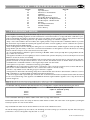
Under normal conditions the fan should only run for a few
moments at high speed before the pressure switch detects airFan starts and neon indicator extinguishes, fan continues to run flow, dropping the fan down to normal speed.
Check all plugs, connector and continuity of wiring from terminal 2 on
in high setting but solenoid does not open.
the control box (see figure 29) and the middle terminal of the pressure
switch.
Check fan outlet and flue pipe for obstruction. Ensure silicone
Fan starts and neon indicator light is illuminated, but then cycles sensing pipes and properly fitted to sensing tubes and pressure
from high to low every few seconds.
switch. Check pressure switch feed pipes are free from obstruction. Check all plugs, connector and continuity of wiring.
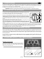
Fan cycles high to low on windy days.
Fan runs in correct sequence but will not pass spillage tests.
This is quite normal on windy days.
In exposed areas a small deflector plate may be fitted to the terminal guard cage to reduce the effects of prevailing winds.
Check
Check
Check
Check
15
test conforms to manufacturers instructions.
for blockages or leaks in flue or fan outlet.
gas type and pressure are correct for appliance.
for adequate ventilation or the effect of extractor fans.
© 2011 Focal Point Fires plc.