1
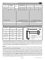
2.0 APPLIANCE DATA
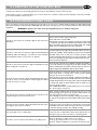
Model
Destination
Country
Natural gas
Full Depth
Slimline
GB - IE
GB - IE
Specifications
Main burner injector
Oxypilot (Natural Gas Models)
Gas Control (All Models)
Gas Inlet
Ignition
Spark Gap (± 1.0mm)
Electrical supply
Power consumption
Fuse rating
Approximate weight
Flue specification
Efficiency
Efficiency class
Cat
I2H
I2H
GB IE
Inlet/Operating
Pressure (±2.0 mbar)
Max Energy Input (kW)
Min Energy Input (kW)
G20
G25
G30
G31
Gross
Net
Gross
20
-
-
-
6.2
5.6
3.5
20
-
-
-
6.8
6.1
3.5
Net
3.15
3.15
Full Depth Models
Slimline Models
Stereo size 79
Stereo size 78
SIT 9081
SIT 9090
Copreci 21400 Series
Copreci 21400 Series
8mm Inlet restrictor elbow
8mm Inlet restrictor elbow
Piezo Spark
Piezo Spark
4.0mm
4.0mm
230 V AC, 50 Hz
230 V AC, 50 Hz
0.3A Running, 0.4A Start-up
0.3A Running, 0.4A Start-up
3A
3A
Fire unit 20KG, Fan unit 12KG
Fire unit 20KG, Fan unit 12KG
Twin wall circular provided as part of appliance. No additional or alternative flue
may be used. Outer flue tube diameter 120mm.
53% Gross, 58.8% Net
52.5% Gross, 58.3% Net
2
2
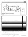
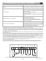
3.0 INSTALLATION REQUIREMENTS
Dimension
Full Depth Models
Slimline Models
‘A’
205mm
150mm
‘B’
170mm
125mm
‘C’ Minimum
100mm
100mm
‘C’ Maximum
600mm
600mm
‘D’
90mm
90mm
Figure 1
B
A
C
D
A = Firebox fitting depth (inc. 25mm for
Rockwool jacket
B = Depth from rear of firebox frame to spigot
C = Flue pipe length
D = Permitted recess depth of terminal box
(Optional).
Internal
This appliance MUST NOT be installed into a room containing a bath or shower, or where steam may be present. It is not recommended that the appliance be installed in areas where it is likely to be directly exposed to persistent strong draughts, that may be generated by outside doors, windows, air vents, air conditioning units, extractor fans, ceiling fans etc. See section 4.1 for more information on ventilation. The firebox must be installed onto a suitable non-combustible insulating surface at least 12mm thick, covering the entire base area of the box.
This appliance is suitable for use with a “lightweight” surround and back panel of 150ºC minimum rating. A suitable gas supply and an
electrical 3 Amp fixed fused spur are both required near the intended appliance site.
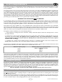
External
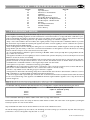
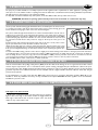
Please refer to the diagram on the following page for more details of the most suitable site for the fan terminal. The terminal must be
located so that the outlet is not obstructed in any way allowing poor disposal of combustion products. A safety cage should be fitted in
place over the terminal to ensure compliance with Byelaws.
Terminals located in passageways between two properties, public footpaths or which might discharge over the same may be subject to
local Byelaws on items such as minimum distances for projection. In these circumstances it is the installers responsibility to check that
the location of the terminal does not infringe any Byelaws. If in any doubt about flue terminal location, especially with regards to garages
and car ports then further advice should be sought from GAS SAFE or the manufacturer. Avoid locating the terminal in close proximity to combustible materials, such as plastic drainpipes and fences. If these are impossible to avoid, then a suitable metal deflector must
be used if the flue gasses begin to heat the object. For minimum standard dimensions of clearance see section 4.0. Covered areas such
as under car ports should be avoided but if no alternative is available the following notes should be adhered to; The covered area should
have at least two open sides (i.e. a roof and ONE supporting wall). If more than one side is filled, then advice must be sought on the
location’s suitability. Any openings into dwellings such as doors, windows and air vents under the covered area must be at least 1200mm
away from the terminal position. If the roof is constructed from plastic material, great care must be taken with the installation as there
is no simple method of protecting this type of roof from heat build up.
3
© 2011 Focal Point Fires plc.