1
6.0 FUEL BED LAYOUT - FULL DEPTH MODELS CONTINUED
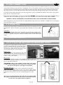
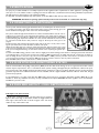
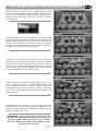
2. Position the front coal strip as shown in figure 4. The rear edge of
the front coal strip should fit in front of the burner rail. Again, do not
to place on top of the burner rails. When the front coal is in position
bend up the three metal tags at the front of the tray to retain as
shown in figure 5.
GB IE
Figure 4
Figure 5
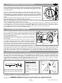
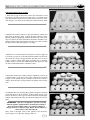
3. Coals. All of the coals are the same. Take five coals and place them
as shown in figure 6. Care should be taken to ensure that the coals
bridge the gap between the front coal and the four coal supports at
the front of the matrix. Care should also be taken not to push the
coals right down between the coal supports, as this can detract from
the flame picture when the appliance is running.
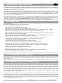
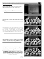
4. Take five more moulded coals and position as shown in figure 7 to
form the ‘second row’ of the fuel effect. The coals may be rotated as
desired to fit into the gaps between the coal supports in order to
create a random, realistic effect. Again, remember not to push the
coals down too far into the valleys between the coal supports as this
can have a detrimental effect to the flame picture.
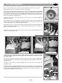
5. Take another four coals and place behind the second row of coals
as shown in figure 8, in order to complete the third row. The coals
may be orientated as desired to achieve a realistic effect. Keep the
spacing between the coals even and uniform. The two coals at the
ends of the row may be placed rearwards, towards the back corners
of the fuel matrix.
6. Finally, take the two remaining coals and place at the back of the
fuel matrix, in the centre as shown in figure 9. Adding these coals
should complete the appearance of the fuel bed giving an even distribution of equally spaced coals.
IMPORTANT : The fire is designed to operate correctly
with the coals supplied when assembled according to the
instructions. Never add to the sixteen coals, or change
them for a different type. Never throw rubbish or other
matter onto the coal bed.
3
Figure 6
Figure 7
Figure 8
Figure 9
© 2011 Focal Point Fires plc.