1
2
Laboratory Exercise #2
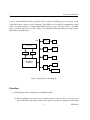
processor after the FPGA has been programmed. This is useful for initializing regions of memory outside
of the FPGA and for general software debugging. The UART is used for RS232 communication, which
will be our primary method of communicating with the microprocessor for the next few labs. The GPIO
blocks provide the microprocessor with a means of controlling the LEDs and reading user input from the
DIP switches and push buttons.
PLB
JTAG
Debug
Block RAM
BRAM Cntlr
iLBM
UART
RS232
GPIO
LEDs
BRAM Cntlr
dLBM
MicroBlaze
Processor
Switches
GPIO
Push Buttons
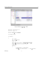
Figure 1: MicroBlaze System Diagram
Procedure
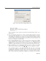
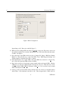
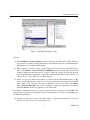
1. Launch Platform Studio and run Base System Builder (BSB).
(a) Before beginning, create a directory in your home folder for today’s lab. Try to avoid spaces and
special characters in the directory name as they have the potential for causing problems during
2
ECEN 449