1
Laboratory Exercise #2
7
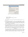
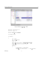
Figure 6: Software Setup
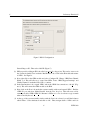
for the ‘SPLB Clk’ port. Set the net connection to ‘sys clk s’.
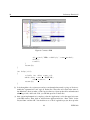
(g) We are almost done adding a GPIO IP to our microprocessor system! Now we must specify an
address range on the bus for our LEDs module. To do this, select the ‘Addresses’ tab under the
system assembly window. Set the ‘size’ field of ‘LEDs’ to 64K and hit the ‘Generate Addresses’
button. This will adjust the address ranges for other IP blocks in our system. Ensure there are
no overlapping address.
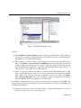
(h) While under the ‘Addresses’ tab, change the sizes of both the dlmb cntlr and ilmb cntrl to 128K
and regenerate the hardware addresses. It turns out that 64K is not enough memory for our
system when using printf in your application code.
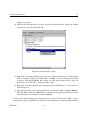
(i) The final step is to modify the ucf to specify the pin locations of LEDs ext. Click on the ‘Project’
tab in the upper left corner of the XPS window. Locate the ‘data/system.ucf’ file and double click
on it. In the editor window that appears, append the following code to the ucf:
NET
NET
NET
NET
"LEDs_ext<0>"
"LEDs_ext<1>"
"LEDs_ext<2>"
"LEDs_ext<3>"
LOC
LOC
LOC
LOC
=
=
=
=
"H18" ;
"L18" ;
"G15" ;
"AD26" ;
Does this code snippet look familiar? Be sure to save the ucf when you are done editing it.
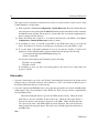
3. After modifying the ucf, we must build our hardware system and generate the appropriate software
ECEN 449
7