1
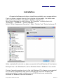
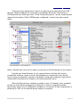
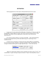
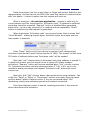
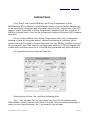
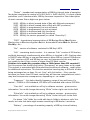
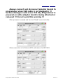
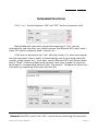
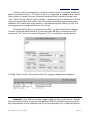
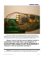
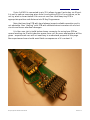
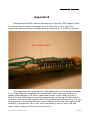
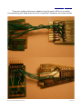
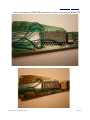
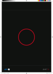
IR Key Programmer
Extended
User Manual
Information contained in this publication regarding device applications and the like is provided only for your convenience and may
be superseded by updates. It is your responsibility to ensure that your application meets with your specifications.
RADIOLINIJA MAKES NO REPRESENTATIONS OR WARRANTIES OF ANY KIND WHETHER EXPRESS OR IMPLIED,
WRITTEN OR ORAL, STATUTORY OR OTHERWISE, RELATED TO THE INFORMATION, INCLUDING BUT NOT LIMITED TO ITS
CONDITION, QUALITY, PERFORMANCE, MERCHANTABILITY OR FITNESS FOR PURPOSE.
Radiolinija disclaims all liability arising from this information and its use. Use of Radiolinija devices is entirely at the buyer’s risk,
and the buyer agrees to defend, indemnify and hold harmless Radiolinija from any and all damages, claims, suits, or expenses resulting from
such use. No licenses are conveyed, implicitly or otherwise, under any Radiolinija intellectual property rights.
® All trademarks mentioned herein are property of their respective companies.
IR Key Programmer Extended User Manual
Revision 1.0
Installation
All required software and drivers should be provided by our representatives.
If not so, please, request them by Your's device serial number. It is visible even
with no drivers installed, using built-in Windows applications.
Open Device Manager by right-clicking “My Computer” and after that click
“Properties” - “Hardware” - “Device Manager”.
Select “IR Key Programmer-Properties”. Select “Details” tab, “Device Instance id”.
Value, marked with red color on above screenshot is Serial Number of Your device.
Example here is for Windows XP, but on Windows Vista or Windows 7 it is similar.
Choice of operating system is up to You, but Windows XP is always recommended
for it's native compatibility with most of USB devices, used for hardware and
engineering tasks. Anyway, stable version of USB libraries are provided by
Microsoft for Windows Vista and Windows 7.
IR Key Programmer Extended User Manual
Revision 1.0
There are many applications, which are able to show information for USB
devices. Official software for such tasks provided by Microsoft Corporation is
UVCView.x86.exe. Running it with “Show Config Descriptors” option enabled gives
required information. Older USBView.exe configured in same way, gives same
result.
Value, marked with red color on above screenshot is Serial Number of Your device.
Provide that Serial Number to our representative and You will receive
compatible software. Have in mind, that software is compiled for Your device,
hence using incompatible, patched, modified or third-party software may lead to
undesirable consequences. Always use trusted providers only!
After installing drivers, software is ready to use. If it doesn't start, probably
You do not have device plugged into USB port or driver's installation failed.
Application starts only if compatible hardware is connected. IR Key Programmer is
powered by USB, so no external power supply is required.
IR Key Programmer Extended User Manual
Revision 1.0
Activation
Starting application shows quite self-explainable welcome screen:
Lower part of screen shows Serial Number of Interface, it's Version and Life.
Percentage of remaining Life, shows how many starts are allowed prior to new
activation. At delivery IR Key Programmer comes with only few percents
remaining Life.
For security reasons device is not fully activated – it has limited lifetime,
enough for testing at factory while manufacturing, but restricting it from
commercial use.
It will be You to activate it in full for first time and enable it's capabilities.
For this purpose button “Request” should be pressed. Field “Serial Number” will
change it's data and will give You eight request bytes – it will look like this:
Bytes are selected by default and You should copy them using “Ctrl+C” key
combination or right-clicking on bytes and select “Copy” from drop-down menu.
IR Key Programmer Extended User Manual
Revision 1.0
Paste those bytes into Your e-mail client or Skype and send to Radiolinia Ltd.
representative. Use text service via SMS if You have that option of communication
with Your dealer – it doesn't matter how this request will reach us.
What is important – do not close application - request is valid only for
current session and You should wait for “Activation code”. If software is restarted,
procedure should be repeated. “Request” button is disabled after generating
session Key - for Your own protection it is random and low repeatable. “Reset”
button is enabled only after request is generated.
When eight bytes “Activation code” are received, paste them in same field
“Serial Number”, replacing request bytes. Activation bytes are unique and onetime usable. In example:
Press “Reset” button and if Your device is genuine it will validate eight
activation bytes and will reset Lifetime counter to 100%. This means You will have
255 starts of software before new “Activation code” will be needed.
Note that “Life” counter doesn't decrement each time software is started. It
is refreshed at lower rate, but actual count is always 255 starts between
activations. “Request” button will become enabled when “Life” counter reaches
7%. Activation procedure could be performed even if “Life” is 0%, so it is not
needed to waste percentage and request “Activation code” before full use of
current one.
Note also, that “Life” counter doesn't decrement while using software – You
could click “Read” or “Write” or “Decrement” buttons how many times You want
and this doesn't affect Lifetime counter. If You are concerned about “Life”
decreasing, simply keep software opened and interface connected.
Each time Lifetime counter is zeroed, resetting procedure is the same as
above described initial activation.
IR Key Programmer Extended User Manual
Revision 1.0
Instructions
Click “Read” with inserted MB Key into IR Key Programmer or with
NEC/Motorola MCU soldered to small adapter board connected aside. Adapter will
be automatically recognized and will prevail over IR mode. Always note, that MCU
adapter board, connected to IR Key Programmer disables it's IR slot, and even if
MB Key is placed there, it will not be recognized, neither will obstruct MCU adapter
operation.
Do not remove MB Key from IR Key Programmer when task is completed –
keeping it there for long time doesn't causes overheating of inductors, which
powers the key. Of course if You are done with Your job, MB Key could be removed
at any moment, but if You intend to perform more tasks on it, IR Key Programmer
is safe and convenient place for it, since MB Key is powered only when operated.
On completion of task screen will look like:
Starting from left top, You could find following data:
“Key” - Key number. Car has total eight keys and this information helps
differentiate current one from the others in the set. Also personalized settings of
seats, mirrors, steering wheel, etc... are linked to this number.
IR Key Programmer Extended User Manual
Revision 1.0
“Status” - hexadecimal representation of MB Key internal state of operation.
Two bytes completes to number of 0x100 (0x14 + 0xEC=0x100). It is form of data
protection, and if checksum fails, MB Key becomes inoperative. Short description
of most common Status digits are given below:
0000 – MB Key is blank (erased state of Key with Motorola processor).
21DF – MB Key is blank (erased state of Key with NEC processor).
04FC – MB Key is programmed, but not activated.
05FB – MB Key is programmed, but not activated.
14EC – MB Key is activated and fully functional.
15EB – MB Key is activated and fully functional.
0CF4 – MB Key for service purposes (so called “Green Key”).
“SSID” - hexadecimal representation of MB System Serial Identificator.
Matches key to Electronic Ignition Switch, Instrument Cluster Module, Central
GateWay, etc...
“Ver” - version of software, contained in MB Key's MCU.
“Life” - remaining starts counter – it is same as “Life” counter of EIS hashes,
and both decrement simultaneously when MB key is inserted in EIS. Starting value
is 196607 when MB key is new and decrements when MB key is used. Differences
in “Life” counters of EIS and MB key are rare, but happens and this may lead to
car unable to start if key counter is bigger than EIS hash counter.
Solution is to make key counter same or little lesser then EIS counter!!!
For this purpose You should click button “Decrement” as many times as You need.
This process is automated with Extended functionalities of software – read further
for additional instructions. This function emulates inserting key to EIS with all data
being exchanged as car does. Do not “play” with this button – if key counter
becomes too lesser than EIS hash counter key will become nonoperational, which
may lead to expensive consequences, depending on car model.
“Frequency” - this helps identify frequency range of key and hence it's
market – 315Mhz is USA standard, 433 MHz is EU standard and custom 512 MHz.
“User Info” - not available on all key's software versions – gives service
information. You could change data using “Write” button right next to the field.
“Extra Info”- not available on all key's software versions – gives service
information. You could change data using “Write” button left prior to the field.
For above “Info” fields You could edit data in fields to whatever suits Your
needs, but note that data might means something to MB dealer / workshop.
“Battery” - percentage of remaining capacity of MB key internal battery.
IR Key Programmer Extended User Manual
Revision 1.0
Except reading capabilities, as name of the product implies, You could also
program keys. Motorola 68HC05E6 MCUs You are able to read / write / erase with
additionally available adapter boards. Both 2 MHz and 4 MHz version are
supported and they could be read / written / erased also on-board without
desoldering. See Appendix B at the end of this document for further instructions
how to connect Motorola to IR Key Programmer.
Same applies to NEC MCUs – You could read / write / erase with additionally
available adapter boards for both 2 MHz and 4 MHz versions if processor is
desoldered from key's PCB. Available on-board operation without desoldering MCU
is only erasing. Different erasing algorithm is implemented, which allows to use
fewer wires than competitive products, easing whole process and minimizing risk
of MCU's pins damage. See Appendix A at the end of this document for further
instructions how to connect NEC to IR Key Programmer.
When key is ready for erasure, just click button “Erase” and appropriate
message will appear, indicating operation in progress.
If processor is soldered on adapter board, software checks success of
erasure and upon completion of it, You will be able to read processor for
confirmation. It is always advisable to solder NEC on adapter for guaranteed
results. Not only because of golden plated adapter PCB, which guarantees proper
contact and long life of board, but also following processes of programming,
activating, Life decreasing operations are faster with adapter. Also if You program
wrong file into key it is very easy to erase it and reprogram with correct dump.
Just after all tasks are finished and MCU is prepared for use in car, You could
solder it back to key's PCB and make a final reading via IR before using with car.
For both Motorola and NEC “Read” / “Write” are available via IR also !!!
IR Key Programmer Extended User Manual
Revision 1.0
Always connect and disconnect adapter boards to
programmer when USB cable is not plugged in !!!
Serious damages could occur if IR Key Programmer is
powered on while adapter board is being attached or
removed !!! Do not avoid this warning !!!
When processor is erased and You click “Read” screen looks like:
Above screenshot is for Motorola MCU and below is for NEC MCU:
IR Key Programmer Extended User Manual
Revision 1.0
Note that fields “Key”, “SSID” and “Life” should be blank (showing dashes)
and “Status” field should show inoperative state of key.
Next step is writing new data. Appropriate button will be activated after
loading key dump. If You are working with Motorola MCU, please, select type of
key dump – drop-down menu is available corresponding to last three digits of MCU
marking. In example if marking is “MA 567 880 011” select 011 before loading.
For key's dump calculating solution, contact Radiolinija Ltd. sales
representatives. Or continue with solution currently in use by You. Software
recognizes most of key dumps formats. If You experience troubles loading data,
please, contact us for upgrade. If data is loaded correctly corresponding fields will
show values from dump and “Write” button will be activated.
Clicking it will produce screen like this:
Upon completion You could activate that key if it will be used as
replacement of existing / lost key. If You are programming new key for that EIS,
then skip this step. Key will be activated automatically when first inserted into EIS.
Remark: Two buttons in section “Power” are turning On and Off inductor of
IR Key Programmer. With their help You could check if inductive coil inside MB key
has malfunctioned or is operative. Just click “ON” button and measure voltage
across inductor. Or if key is not disassembled, press LOCK / UNLOCK button – if key
LED blinks this means coil has failed. Click “OFF” when completed.
Do not hold “ON” function for long time – overheating could appear !!!
IR Key Programmer Extended User Manual
Revision 1.0
Extended functions
Click “>>>” located between “ON” and “OFF” buttons (marked in red).
New window will open which allows decrementing of “Life” counter
automatically and few other very helpful options like Motorola MCU read / write /
erase, IR custom commands send / receive, etc...
If You wish to decrement key “Life” with big number (i.e. when exchanging
old style big plastic keys to newer chromed design and You are using same Key
number, same hashes, etc... from data, read by Mototola MCU with below shown
button “Read” in Motorola Boot mode section), then enter number of counts to
decrement in corresponding field and click “Decrement”. Software will inform You
how tasks is progressing and screen will look like:
Remark: Mind EIS current hash “Life” counter when performing this operation.
IR Key Programmer Extended User Manual
Revision 1.0
Another useful functionality is ability to send custom commands to MB key.
What should be written in “IR bytes to send” is command in hexadecimal format.
Also number of bytes You want to send should be filled in decimal format into
“Len” field. Clicking “Send” button results in transmitting of command via IR and
receiving response if such exists. Not all possible commands have appropriate
response. Be careful with that function – experimenting with MB key is fun, but
consequences and responsibility are only Yours.
Example will be given for that functionality – as discussed above lifetime
counter should be decremented. To simulate that MB Key is inserted into EIS,
command “26” have to be send. Response “27” is received as shown below:
Clicking “Save” button will produce text file, logging request and response.
Remark: Some MB key models support different IR commands set. Results
from Your experiments may vary with different MB key software versions and IR
Key Programmer and its software are not to be blamed for any undesired effects.
IR Key Programmer Extended User Manual
Revision 1.0
Appendix A
Erasing NEC MCU without desoldering it from key's PCB requires skills for
connecting thin wires to processor pins. Do this with a lot of care! Use appropriate
wires and tools. First desolder and lift a little bit pin 25 of MCU as shown:
After that solder thin wires from adapter board pads with corresponding
names to pin 19, pin 25 of MCU and GND of PCB. For different models of key's PCB
find correct spot to solder wires for GND and pin 19. On most of the models pin 19
has test pad routed to it and is not necessary to solder wire directly to this pin.
Just locate where is it's test pad and solder wire there. Do not overheat MCU pins!
Locating GND (ground) is easy, so choose bigger wire for it to guarantee
proper operation of device.
With all wires connected PCB has to look like (image is for reference only):
IR Key Programmer Extended User Manual
Revision 1.0
Now You are ready to connect adapter board to IR Key Programmer and
perform erasure. On most of key's PCB models when erasing is completed key's
LED blinks. You could observe it as with this erasing method software can't check
if it's completed or not. For safer procedure solder MCU on adapter board!
Always connect and disconnect adapter boards to
programmer when USB cable is not plugged in !!!
Serious damages could occur if IR Key Programmer is
powered on while adapter board is being attached or
removed !!! Do not avoid this warning !!!
Remark: There is additional wire on above image, soldered to pin 4 of MCU.
It's optional and for experienced users only! Read next page for more details!
IR Key Programmer Extended User Manual
Revision 1.0
If pin 4 of MCU is connected to pin 25 it allows to read / write key via IR port.
It is not so safe as removing wires from it and putting PCB in it's enclosure, so do
not try what is shown below if You are not sure You could keep key PCB in
appropriate position and distance into IR Key Programmer.
Note that touching PCB with hand always impacts reliable operation and is
not advisable. Also “playing” with PCB with soldered wires increases risk of short
circuits and hence eventual damages.
It is Your own risk to build below shown connector for using bare PCB as
normal working via IR with inductive power from coil. No more explanations will be
given – experienced user will not need any to understand purpose of this page.
Non-experienced user should avoid fatal consequences of it's content ☺
IR Key Programmer Extended User Manual
Revision 1.0
Appendix B
Erasing Motorola MCU without desoldering it from key's PCB requires skills
for connecting thin wires to processor pins. Do this with a lot of care! Use
appropriate wires and tools. Desolder and lift a little bit pin 1 of MCU as shown:
This operation carry eventual risk of damaging pin, so it is always advisable
to to solder Motorola on adapter for guaranteed results. Not only because of
golden plated adapter PCB, which guarantees proper contact and long life of
board, but also following processes of programming, activating, Life decreasing
operations are faster with adapter. Also if You program wrong file into key it is very
easy to erase it and reprogram with correct dump. Just after all tasks are finished
and MCU is prepared for use in car, You could solder it back to key's PCB and
make a final reading via IR before using with car.
IR Key Programmer Extended User Manual
Revision 1.0
Choose correct adapter board for 2 MHz or 4 MHz versions of MB Key.
Markings on quartz resonator is visible and helps You identify it very easy on PCB.
Images are for reference only and vary with different PCB hardware versions !
IR Key Programmer Extended User Manual
Revision 1.0
There are visible printings on adapter board to which MCU pin to solder
corresponding pad. Keep wires as short as possible! Examples are shown below:
IR Key Programmer Extended User Manual
Revision 1.0
Here is example of 2 MHz PCB connections, and at the bottom is 4MHz PCB:
IR Key Programmer Extended User Manual
Revision 1.0
Important Notice
Always connect and disconnect adapter boards to
IR Key Programmer with USB cable not plugged in !!!
The ONLY right way to connect adapter to IR Key
Programmer is shown below. It doesn't matter if MCU
is soldered directly on adapter or connected with
wires. Orientation of adapter should be like this:
IR Key Programmer Extended User Manual
Revision 1.0