1
!
"
#
User Manual
Version 1.0, English
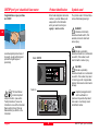
DISTOTMpro4 / pro4 a hand-held laser meter
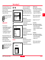
Product identification
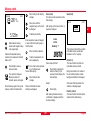
Symbols used
Congratulations on your purchase
of a DISTO!
Enter model designation and serial
number in your User Manual, and
always refer to this information
when you need to contact your
agency or service centre.
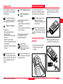
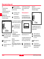
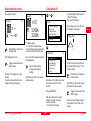
The symbols used in this User Manual have the following meanings:
Leica Geosystems products are of
top quality, are top performers and
provide the higest degree of
productivity.
This User Manual
contains important
safety instructions (see section
"Safety Instructions") as well as
instructions on use of the instrument.
Read carefully through the User
Manual before you switch on the
instrument.
English
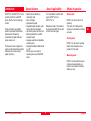
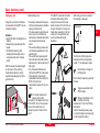
DANGER:
Indicates an imminently
hazardous situation which, if not
avoided, will result in death and
serious injury.
PD-Z01
en
Model: DISTO
WARNING:
Indicates a potentially
hazardous situation or an unintended
use which, if not avoided, could
result in death or serious injury.
CAUTION:
Indicates a potentially
hazardous situation or an unintended
use which, if not avoided, may result
in minor injury and/or in appreciable
material, financial and environmental
damage.
Serial no.:
Important paragraphs which
must be adhered to in
practice as they enable the product
to be used in a technically correct
and efficient manner.
4
DISTO pro4 / pro4 a-1.0.0en
Contents
Measuring from flat planes ..................................................................................... 17
Measuring from corners .......................................................................................... 18
Measuring from edge .............................................................................................. 18
Measuring with stand .............................................................................................. 18
Measuring with alignment aid ................................................................................. 18
Measuring with accessories ................................................................................... 19
Product identification ..................................................................................................... 4
Symbols used ................................................................................................................. 4
Introduction ...................................................................................................... 7
Special features ............................................................................................................. 7
Area of applicability ........................................................................................................ 7
Modes of operation ........................................................................................................ 7
Normal mode ............................................................................................................. 7
Pointing mode ........................................................................................................... 7
Measuring mode ........................................................................................................ 7
Simple Calculations ...................................................................................... 19
Length ........................................................................................................................... 19
Total height, total distance ...................................................................................... 19
Partial heights, partial distances ............................................................................ 19
Doubling a measured value .................................................................................... 19
Area .............................................................................................................................. 20
Volume .......................................................................................................................... 20
Instrument description ................................................................................... 8
Standard equipment ...................................................................................................... 8
Basic instrument ............................................................................................................ 9
Display .......................................................................................................................... 10
Special symbols ...................................................................................................... 10
Keypad ......................................................................................................................... 11
Overview .................................................................................................................. 11
Table of characters .................................................................................................. 11
Inserting / replacing the batteries ................................................................................ 13
Menu Functions ............................................................................................. 20
Measurement settings (1) ............................................................................................ 20
Measurement reference (1.1) ................................................................................. 20
Add / Subtract (1.2) ................................................................................................. 21
Time delay release (1.3) ......................................................................................... 22
Laser (1.4) ............................................................................................................... 23
Tracking (1.5) .......................................................................................................... 24
Data transfer (1.6) ................................................................................................... 24
End covers (2) .............................................................................................................. 24
Without end cover (2.1) .......................................................................................... 24
Adapter end cover (2.2) .......................................................................................... 25
Recognition (2.3) ..................................................................................................... 26
Swivel foot (2.4) ....................................................................................................... 26
Alignment aid (2.5) .................................................................................................. 27
Basic settings (3) ......................................................................................................... 27
Units (3.1) ................................................................................................................ 27
Language (3.2) ........................................................................................................ 28
Beep (3.3) ................................................................................................................ 28
Reset (3.4) ............................................................................................................... 28
Lighting (3.5) ........................................................................................................... 28
Switch off (3.6) ........................................................................................................ 29
How to use instrument ................................................................................. 13
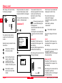
Switching on DISTO .................................................................................................... 14
Switching on DISTO for the first time .................................................................... 14
Switching on Pointing mode ................................................................................... 14
Switching off DISTO .................................................................................................... 15
Measuring ..................................................................................................................... 15
Using menus ................................................................................................................ 15
Selecting menus / menu functions ......................................................................... 15
Short cut .................................................................................................................. 16
Correct menu selection ........................................................................................... 16
Reset menu functions ............................................................................................. 16
Quit menu ................................................................................................................ 16
Using end covers ......................................................................................................... 16
Automatic end cover recognition ............................................................................ 16
Changing end covers .............................................................................................. 17
DISTO pro4 / pro4 a-1.0.0en
5
English
en
Contents, contd.
en
Basic functions (4) ....................................................................................................... 29
Maximum tracking (4.1) .......................................................................................... 29
Minimum tracking (4.2) ........................................................................................... 29
Required distance (4.3) .......................................................................................... 30
Pythagoras (4.4) ...................................................................................................... 33
Height (4.5) .............................................................................................................. 35
Accuracy (4.6) ......................................................................................................... 36
Average value (4.7) ................................................................................................. 36
Calculation (5) .............................................................................................................. 37
Triangle SSS (5.1) ................................................................................................... 37
Triangle SH (5.2) ..................................................................................................... 38
Trapezium HSH (5.3) .............................................................................................. 39
Trapezium HSD (5.4) .............................................................................................. 40
Gable area (5.5) ...................................................................................................... 41
Circle (5.6) ............................................................................................................... 42
Space (5.7) .............................................................................................................. 43
Memory (6) ................................................................................................................... 44
1 - 9 recall key (6.1) ................................................................................................ 44
1 - 9 recall key (6.2) ................................................................................................ 45
Stack (6.3) ............................................................................................................... 46
Data (6.4) ................................................................................................................. 47
Calculator (7) ................................................................................................................ 50
Division (7.1) ............................................................................................................ 50
x2 (7.2) ...................................................................................................................... 50
Square root (7.3) ..................................................................................................... 50
Accessories .................................................................................................................. 52
Accessories for measurements .............................................................................. 52
Accessories for data interface ................................................................................ 53
Transport accessories ............................................................................................. 53
Safety Instructions ........................................................................................ 53
Use of the Instrument .................................................................................................. 53
Permitted use .......................................................................................................... 53
Prohibited uses ........................................................................................................ 53
Limits to use ................................................................................................................. 54
Areas of Responsibility ................................................................................................ 54
Hazards in Use ............................................................................................................. 54
Important hazards in use ........................................................................................ 54
Laser Classification ...................................................................................................... 55
Labelling .................................................................................................................. 56
DISTO with Telescopic Viewfinder .............................................................................. 56
Electromagnetic Compatibility (EMC) ......................................................................... 56
FCC Statement (applic. in U.S.) .................................................................................. 57
Care and Storage ........................................................................................... 58
Care .............................................................................................................................. 58
Clean and dry .......................................................................................................... 58
Storage ......................................................................................................................... 58
Transport ...................................................................................................................... 58
Despatch ...................................................................................................................... 58
Technical Data ............................................................................................... 59
User Information ............................................................................................ 51
Remarks on Measuring Accuracy ............................................................................... 60
Possible method of calculating the standard deviation s: ..................................... 60
Accuracy Tests ............................................................................................................. 60
Range ........................................................................................................................... 51
Rough surfaces ............................................................................................................ 51
Transparent surfaces ................................................................................................... 51
Wet, smooth and high-gloss surfaces ......................................................................... 51
Inclined, round surfaces .............................................................................................. 51
Free- handed aiming ................................................................................................... 51
Measuring in the field .................................................................................................. 51
Setting viewfinder .................................................................................................... 51
English
Message Codes ............................................................................................. 61
Short cut index .............................................................................................. 62
6
DISTO pro4 / pro4 a-1.0.0en
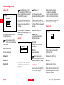
Introduction
Special features
Area of applicability
Modes of operation
DISTOTM pro4 and DISTOTM pro4 a, the
top of the line of the new DISTO
series, offer the most in measuring
comfort.
Robust; proven reliability on
construction sites
Clear, lit displays
Alphanumeric keypad
Integrated pocket calculator, extensive functions for calculations
User friendly menus with short cuts
Memory allocation for up to 800
measured values
Language selection and selectable
measuring units
Integrated interface for data transfer
to a PC
DISTOTM pro4 a: the utmost in
measuring accuracy of the DISTO
series
This User Manual is valid for both
types, DISTOTM pro4 and
DISTOTM pro4 a.
Normal mode
These instruments are perfectly
suited for quick width and distance
measurements, followed by
computations of partial distances,
areas, volumes, etc.
The three end covers supplied are
used to set the desired measurement
references (for corners, angles,
edges, tripod, etc.).
References made in this manual to
the product name DISTO, are valid
for both instrument types.
DISTO is on, but the laser is not
operating.
This mode is for making entries,
carrying out calculations and calling
up menus.
Pointing mode
DISTO is on, the laser is operating.
Objects to be measured can be
pointed at in this mode.
Measuring mode
DISTO is on and performs single or
continuous measurements (e.g.
minimum and maximum tracking,
staking out, etc.).
DISTO pro4 / pro4 a-1.0.0en
7
English
en
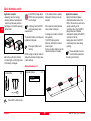
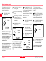
Instrument description
PD-Z03
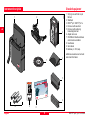
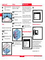
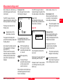
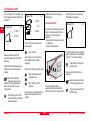
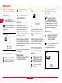
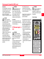
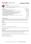
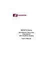
Standard equipment
2
1
en
3
7
4
1 Carrying case with belt loop at
the back
2 Waistband
3 DISTOTM pro4 / DISTOTM pro4 a
4 End cover with swivel foot
5 End cover with positioning
bracket/alignment aid
6 Adapter end cover
7 CD-ROM with interface software
and online documentation
8 User Manual
9 Quick Guide
10 Batteries (4 x 1.5V, AAA)
Additional accessories can be found
under User Information.
5
6
10
English
9
8
8
DISTO pro4 / pro4 a-1.0.0en
PD-Z02
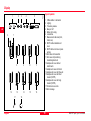
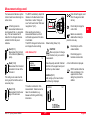
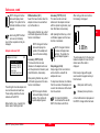
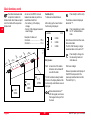
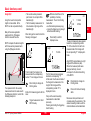
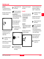
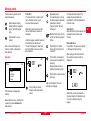
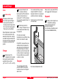
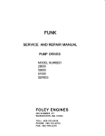
Basic instrument
1
2
10
3
1
2
3
4
5
6
7
8
Alphanumeric keypad
LED display
Measuring optics
Laser beam exit
Stand connection
End cover release button
Battery compartment cover
Sensors for automatic end cover
recognition
9 Magnetic plate for attaching
accessories
10 Interface slot cover
4
5
6
9
7
8
DISTO pro4 / pro4 a-1.0.0en
9
English
en
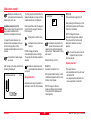
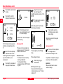
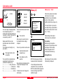
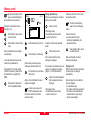
Display
2
3
4
Special symbols
PD-Z04
1
5
1
2
3
4
5
6
7
Offset addition / subtraction
Lighting
Time delay release
Beep on / off
Battery full / empty
Laser active
Measurement reference (front,
stand, rear)
8 DISTO without detected end
cover
9 DISTO without end cover (menu
setting)
10 End cover with swivel foot
11 End cover with positioning
bracket/alignment aid
12 Adapter end cover without
attachments
13 Adapter end cover with stand
14 Adapter end cover with free end
15 Adapter end cover with short
bracket (723775)
16 Adapter end cover with long
bracket (723776)
17 Contact service centre
18 Error message
en
6
7
12
17
English
8
9
10
11
13
14
15
16
18
10
DISTO pro4 / pro4 a-1.0.0en
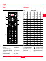
Keypad
Table of characters
Key
PD-Z05
Overview
6
1
1
.
+
-
,
?
!
&
1
2
A
B
C
2
Ä
À
Á
Â
Ã
Å
Æ
Ç
a
b
c
2
ä
à
á
â
ã
å
æ
ç
3
D
E
F
3
É
È
E
Ë
d
e
f
3
é
è
ê
ë
4
G
H
I
4
Ì
Í
Î
Ï
ì
í
î
ï
Ö
Ñ
Ò
Ó
Ô
Õ
Ø
ñ
ò
ó
ô
õ
ø
2
3
7
4
8
5
g
h
i
4
5
J
K
L
5
j
k
l
5
6
M
N
O
6
m
n
o
6
ö
7
P
Q
R
S
7
p
q
r
s
7
8
T
U
V
8
Ü
Ù
Ú
Û
t
u
v
8
ü
ù
ú
û
W
X
Y
Z
9
w
x
y
z
9
9
1
2
3
4
5
Menu key
Power on and measuring key
Multiplication / time delay release
Clear key
Alphanumeric keypad 0-9
DISTO pro4 / pro4 a-1.0.0en
assigned characters
This table contains all displayable
characters that can be entered
through the keypad.
6 Plus / navigation key,
up
7 Minus / navigation key,
down
8 Result / Enter key
11
The symbols on the keys are
limited to the most commonly
used characters, due to the lack of
space.
English
en
Keypad, contd.
Menu key
To call up the main menu.
After entering a numeric value
en through the keypad, (multiple)
presses on the menu key adds the
desired unit (e.g. m, m2, m3).
Power on and measuring
key
Pressing the power on and
measuring key in Normal mode
switches the laser to permanent
operation (1.4.2).
Pressing the power on and
measuring key in Pointing mode
starts continuous measurement
(Tracking, 1.5.1) or, if using certain
menu functions maximum (4.1) or
minimum tracking (4.2).
A tangible elevation in the
middle of the keys facilitates
correct key presses e.g. in darkness.
English
Multiplications / Time delay
release
Press clear key for a long
period to quit the menu
section and to return to the basic
settings in normal mode.
To multiply two or more measured or
numeric values (see section "Simple
calculations").
Alpha numeric keypad 0-9
The 0 key displays a blank space.
The 1-9 keys represent characters
(see Table of characters).
A brief press in Pointing mode starts
the time delay release; pressing and
holding increases time delay. Upon
release the timer starts.
The availablity of these characters
depends on the currently selected
function.
To switch between capital and small
letters during text input.
Input of numbers
Clear key
Assigned text characters of the keys
are blocked.
A brief press (Clear Entry) deletes
the last entry or the intermediate
result of a computation.
Key 1 pressed twice briefly enables:
During computations within a
menu function or in selecting
a menu setting the last display or
input is deleted as long as the result
/ enter key has not been pressed.
- a minus sign to be input as the first
character,
- a decimal point to be placed after
having entered at least one number.
Briefly press clear key one or more
times to move backward through the
menu.
A long press on the 0 key calls up
memory allocations for the input
values:
Press 0 until a beep sounds
(approx. 1 sec). After release, the
contents of keypad memory 1 is
displayed.
Press 0 until two beeps sound
(approx. 2 sec). After release, the
first memory contents of the stack is
displayed.
Detailed information can be
found in the section Menu
functions under "Memory".
Text or data input in the data
memory
Brief repeated presses on the keys
displays the different layers of
assigned characters.
Example: 1 x key 2 = A / a
2 x key 2 = B / b, etc.
Briefly press to switch
between capital / small
letters.
12
DISTO pro4 / pro4 a-1.0.0en
How to use instrument
Result ( = ) / Enter key
Press briefly to:
- finalize a computation and to
display the result.
- end a menu function and display
the result.
- confirm an input or setting.
- confirm a single measurement in the
menu function.
- jump from the menu to the selected
sub menu.
Press and hold to save a
value into the data memory.
With menu functions, all results are
saved in sequence to the data
memory.
DISTO pro4 / pro4 a-1.0.0en
Minus / navigation key
(down)
Press respective keys briefly in
normal mode to:
- enter an addition or subtraction in a
computation
- move up or down from one entry to
the next in menus.
Press respective keys briefly in
Pointing mode to change
measurement reference.
Press both keys
simultaneously to turn
DISTO off in Normal and
Pointing mode.
For a first time use, insert new
batteries into the DISTO (for battery
type read the technical data sheet).
This symbol appears in the
display as soon as the
battaries are empty and need
to be replaced.
2. Press both locking clips together
with fingertips and pull out battery
cover.
When changing batteries, the
settings and saved measured
values remain unchanged in the data
memory.
Inserting / replacing the
batteries
1. Press end cover release button,
and pull the end cover off the
instrument.
Or as an alternative, press
and hold one of the keys and
then press the other.
3. Remove empty batteries, if any. Fit
new batteries the right way round.
PD-Z08
If one of the 0-9 keys are
pressed for a long time, its
number appears on the screen.
Plus / navigation key (up )
PD-Z06
After a long pause or by pressing
another key the cursor changes to
the next display.
PD-Z07
Keypad, contd.
13
English
en
Insert / replace batteries, contd.
IMPORTANT:
Switching on DISTO
4. Replace battery cover.
1 Deutsch
2 English
3 Français
Select desired language with
these keys.
Press briefly.
DISTO is on and in nomal mode.
The display shows the basic settings
with the last mesured value.
A horizontal bar marks the selection.
A brief press confirms the
selection.
PD-Z09
5. Place end cover in slot and push
in until it locks.
English
PD-Z10
The proper way of inserting the
batteries is shown on the side of the
battery compartment.
en Always replace the entire set of
batteries. Never mix old and new
ones.
Never use batteries made by different manufacturers or batteries of
different type.
After a "Thank you" text, the basic
settings display appears.
Language selection can be changed
at any later time in menu "Language"
(3.2) .
3.504m
It is possible to load an additional
fourth language via the DISTO
interface.
Switching on DISTO for the first
time
Any further language loaded via the
interface after the fourth one,
automatically replaces that fourth
loaded language.
Read instructions for the DISTO
Online Software on the CD-ROM
supplied.
Switching on Pointing mode
Briefly press.
DISTO changes from Nomal mode
into Pointing mode and the laser
lights up.
This symbol appears in the
basic settings display while
the laser is on.
If within 30 seconds no measurement
is triggered the laser turns off
automatically to save batteries.
DISTO is then back in Normal mode.
Press again to start laser and
to switch into Pointing mode.
When following the described
procedure, the language selection
menu is displayed first.
English
14
DISTO pro4 / pro4 a-1.0.0en
Switching off DISTO
Measuring
Using menus
To save batteries, the DISTO
automatically switches off after 90
seconds if no key is pressed in that
time, or it is not in Permanent mode.
Switch on DISTO
From the main menu, various
submenus can be called up from
which functions can be selected
(refer to short cut index).
Manually, the DISTO can be
switched off in different ways .
1. In Normal mode
Press both keys
simultaneously or hold one of
both keys and then press
second key.
or select menu function
"Switch off" (3.6) :
Press briefly.
Enter short cut.
2. In Pointing mode, in a menu
function, etc.:
Press one or more times until
the basic settings in Nomal
mode are displayed.
Then press both keys
simultaneously or hold one of
both keys and then press
second key.
DISTO pro4 / pro4 a-1.0.0en
Press briefly.
DISTO is in Normal mode.
Distance measurement
Selecting menus / menu functions
Press briefly in Normal mode
to display the main menu.
Press again briefly to activate
Pointing mode.
menu
Aim at object to be measured.
1 measure settings
2 end cover
3 basic settings
4 basic functions
5 calculation
6 memory
Press again to trigger
distance measurement
The result is displayed in the
selected unit.
Repeated presses scrolls
down and highlights the
individual menu items.
menu
en
2 end cover
3 basic settings
4 basic functions
5 calculation
6 memory
7 calculator
If required, press repeatedly
to scroll up to get back to
individual menu items.
A brief press confirms
selection.
The upper line of the main menu
shows the selected menu item with
numeric short cut.
Now a submenu appears or a beep
sounds, while briefly displaying a
confirmation.
The horizontal black bar marks the
selected menu item. If all menus are
not displayable at once, a vertical roll
bar appears at the right side,
indicating the availability of further
items.
15
English
Using menus, contd.
en
done
Short cut
Each submenu function has a
numeric code, a so called short cut
number.
By entering the short cut number, a
submenu or a menu function can be
selected directly.
Short cut numbers are listed
in brackets when menus or
menu functions are being described
(e.g. 1.4.2). An overview of short cut
numbers can be found in the short
cut index and in the Quick Guide.
Using end covers
Press briefly .
Reset menu functions
Enter short cut number,e.g.
1-4-2 for permanent laser
operation.
The "Reset" command (3.4) enables
settings and menu functions to be
reset to a predefined basic setting.
The basic settings are listed in the
description of the menu functions.
Submenus appear step-by-step until
the desired menu function.
Quit menu
After the completion of the entry of
the short cut number the menu
function is carried out and a brief
confirmation is displayed.
Press and hold to quit menu
and to display basic settings
in Normal mode.
Use the short cut to save
time when calling up
frequently used menu functions.
Correct menu selection
DISTO is delivered with the swivel
foot end cover already attached.
Two additional end covers and
accessories, available as options,
enable the instruments to be adapted
to varying measuring situations.
Automatic end cover recognition
Magnetic sensors at the back of the
instrument make it possible to
recognize if an end cover with swivel
foot or positioning bracket/alignment
aid has been attached.
The instrument symbol in the basic
settings display includes the symbol
of the detected end cover and
measurement is referenced
accordingly.
Automatic end cover
recognition
- does not work with the adapter end
cover,
- does not change the preset
measurement reference.
Press briefly to display the
previous menu.
Automatic end cover recognition can
be switched off with menu function
"Recognition off" (2.3.2).
English
16
DISTO pro4 / pro4 a-1.0.0en
Changing end covers
The procedure for changing end
covers is the same for all types.
1. Press release button and pull off
end cover.
choose the
end cover
When using the end cover
with positioning bracket /
alignment aid the release button is
only accessible through the recess in
the end cover.
DISTO
2. Select and place an end cover in
the slot of the casing and push it
down until it locks.
PD-Z09
CAUTION:
Strong magnetic fields can
influence end cover recognition and
cause measuring errors.
Precautions:
Measurements near magnetic fields,
e.g. magnets, transformers... should
be done with the automatic end
cover recognition switched off and
measuring has to be monitored
carefully.
If the menu function "no end cover"
(2.1) is not selected, then as soon as
a measurement is tried without an
end cover, a message is displayed.
PD-Z23
In this case, the end cover has to be
manually selected in the submenu
"End covers" (2).
PD-Z06
Using end covers, contd.
3. A short confirmation is displayed
and then the basic mode. The
DISTO is ready for measurement.
CAUTION:
Wrong measurements after
changing end covers.
Precautions:
Please make a control measurement
every time after changing end
covers.
For measurements without end cover
please enter the menu function "no
end cover" (2.1) after removing the
end cover.
Avoid using DISTO without
end cover, as this will leave
the battery cover exposed and prone
to being damaged.
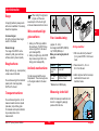
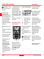
Measuring from flat planes
For stable measuring turn swivel foot
on the end cover by 90°.
DISTO pro4 / pro4 a-1.0.0en
17
English
en
en
The stand as measuring reference
must be entered, when using the
auxiliary stop.
Measuring from edge
Normally the end cover with the
positioning bracket / alignment aid is
used.
PD-Z38
PD-Z12
Using end covers, contd.
Measuring with alignment aid
PD-Z82
The DISTO is ideally suited for
"marking-off ops." - e.g. when staking
out distances.
PD-Z34
Or use the end cover with folded in
positioning bracket / alignment aid.
As an auxiliary stop, the opened
closing cap of the interface plug can
be used.
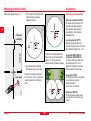
Measuring with stand
Using a stand eliminates shaking
when measuring over a long
distance.
PD-Z30
Exact measurements from corners
can only be made with the end cover
with swivel foot.
Just keep the swivel foot in its initial
position (aligned with the edge of the
end cover).
PD-Z83
Measuring from corners
The stand connection on the bottom
of the casing of the DISTO is
normally used.
The thread of the stand
should not be longer than 5.5
mm or it could damage the casing of
the DISTO.
English
18
DISTO pro4 / pro4 a-1.0.0en
Simple Calculations
Using end covers, contd.
To use the DISTO in high and
hard to reach places, attach
the extendable telescopic rod to the
stand's connection.
Measuring with accessories
46
(2x
A brief press deletes/repeats
the last entry, an intemediate
result or a faulty measured
value.
)
A1
/
mm 4
Optional measurement attachments:
Short bracket (723775)
Long bracket (723776)
PD-Z51
M4
Corrective measures
PD-Z31
The adapter end cover has two
threads for attachments (e.g.
customer specified end covers).
Sequential measurements can be
linked using mathematical functions
or input values.
Corrections are only possible
if the Result / Enter key has
not been pressed.
Length
Total height, total distance
Measurement + measurement = sum
Read user information under
"Accessories".
The DISTO has special menu
functions (2.2.2 and 2.2.3), to set
measuring references with these
optional devices.
Measurement
Addition
Measurement
= Sum
In the same way chain
measurements (any amount
of distance measurements) and
sums of areas / volumes can be
added up.
Partial heights, partial distances
Measurements - measurements =
difference
Measurement
Subtraction
Measurement
= Difference
Doubling a measured value
It is easy to double the measured
value to obtain, e.g. the
circumference of a room:
Measurement
Addition
Measurement
= Sum
(half circumference)
DISTO pro4 / pro4 a-1.0.0en
19
English
en
Length, contd.
Repeat, double measured
value
= Sum (circumference)
Volume
Menu Functions
Measurement x measurement x
measurement = volume
Menu functions are described in the
sequence of their appearance on the
DISTO display, i.e. in an ascending
order of their respective short cut
numbers.
Measurement (e.g. 3.500m)
Multiplication
en
The short cut numers are listed in
brackets behind the menu function.
Measurement (e.g. 8.375m)
PD-Z37
Multiplication
How to use the menus is explained
in section "How to use the
instruments" under "Using menus" .
Measurements (e.g. 2.285m)
Area
= Volume (e.g. 66.980m³)
The short cut numbers
facilitate searching for menu
functions.
Measurement (e.g. 3.500m)
PD-Z40
Measurement x measurement = area
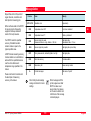
Measurement settings (1)
Multiplication
Measurement (e.g. 8.375m)
1
1 reference
2 offset
3 timer
4 laser
5 tracking
Measurement reference (1.1)
reference
1.1
1 front
2 stand
3 rear
menu
= Area (e.g. 29.313m²)
PD-Z39
measure settings
1 measure settings
2 end cover
3 basic settings
4 basic functions
5 calculation
6 memory
The volume can also be
computed following an area
calculation.
Set measurement reference for the
DISTO, showing where measurements will be made from.
The set measurement reference is
used for all following measurements
until the it is changed again.
Basic setting: Rear (1.1.3)
English
20
DISTO pro4 / pro4 a-1.0.0en
Measurement settings, contd.
In Pointing mode the
measurement reference can
be changed with the (+/-) navigation
keys. The next measurement is
made from the changed reference
and after that from the preset
reference.
Front (1.1.1)
Measurement from the front
of the instrument (Measuring
optics).
Stand (1.1.2)
Measurement from the stand
connected to the rear of the
instrument.
This setting is also used when the
closing cap of the interface acts as
an auxiliary stop.
Rear (1.1.3)
Measurements from the rear
edge of the end cover.
DISTO pro4 / pro4 a-1.0.0en
Enter Add with keypad, recall
it from the keypad or stack
memory.
The DISTO automatically adjusts the
reference to the attached end cover.
Read more in section "Using end
cover" and menu function "End cover
recognition on" (2.3.1).
After selecting and entering a
measurement reference, a short
confirmation appears and the menu
is terminated.
The DISTO changes to Normal mode
and displays the basic settings
Add / Subtract (1.2)
offset
1.2
1 addition
2 subtraction
3 none
Press briefly to display the
units of Add.
PD-Z78
The measurement reference symbol
in basic mode has a referencing line
and an arrow.
Default setting: None(1.2.3)
CAUTION:
After every input of or change
in Add / Subtract, carry out a control
measurement.
Save frequently used Add / Subtract
functions in the keypad memory and
call them up when needed.
Addition (1.2.1)
After calling up this menu function
the following is displayed.
This adds or subtracts to / from
measurements. Tolerances can be
taken into consideration, e.g.
between unfinishing and finishing
dimensions.
addition
+
21
Meters are automaticlly
added without having to
press the menu key.
Press briefly to confirm
entered addition.
Press briefly again to
terminate menu function.
A short confirmation is displayed.
DISTO switches to Normal
mode and displays in the
uppermost line of basic
setting the symbol of the
addition.
1.2.1
0.000m
English
en
Measurement settings, contd.
en
Add
- is valid for all following
measurements,
- is automatically suggested at the
next menu function call up.
Subtraction (1.2.2)
After calling up this menu function,
the following is displayed.
subtraction
1.2.2
-
0.000m
Enter subtraction with keypad
or call it up from the keypad
or stack memory.
Do not enter minus sign for
subtraction.
Press briefly to display unit of
subtraction.
English
Meters are automaticlly
subtracted without having to
press the menu key.
The DISTO changes into Normal
mode and displays the basic
settings.
Press briefly to confirm
entered subtraction.
Time delay release (1.3)
Once (1.3.1)
After calling up the menu function,
the following is displayed.
once
1.3.1
Sets time delay between 5 - 60
seconds after pressing the trigger
key to the start of the measurement.
Press briefly again to
terminate menu function.
A short confirmation is displayed and
the DISTO switches to Normal mode.
timer
1.3
1 once
2 permanent
3 none
The uppermost line of the
basic setting displays the
symbol of the subtraction.
Subtract
- is valid for all following
measurements,
- is automatically suggested at the
next menu function call up.
Default setting: None (1.3.3)
The time delay release permits using
the DISTO in measuring situations
where the keypad is hard to reach.
Off (1.2.3)
Deletes an existing addition or
subtraction.
After a brief press on the Enter key a
confirmation appears and the menu
is quit.
This symbol appears in the
uppermost line of the basic
settings when the time delay
release is in use.
22
10 sec
The suggested delay is only for the
next single measurement and can be
changed as follows:
With the navigation keys.
Each key press increses,
respectively deceases delay
by 1 second.
With a keypad entry.
As long as this key is
pressed the delay increases
until the maximum of 60
seconds is reached.
DISTO pro4 / pro4 a-1.0.0en
Measurement settings, contd.
After a brief press on the Enter key a
confirmation appears and the menu
is terminated.
The DISTO changes into Normal
mode and displays the symbol of the
time delay release in basic settings.
Permanent (1.3.2)
After calling up this menu function,
the following is displayed:
permanent
1.3.2
The delay can also be set in the
Pointing mode:
Keep pressed, until the
desired delay is reached.
The uppermost line displays the
symbol of the time delay release with
the delay below it.
Upon release the remainig seconds
to the measurement is displayed
(e.g. 59, 58, 57,...).
The last 5 seconds are counted
down with a beep sound. After the
last beep the measurement takes
place and the measured value is
displayed.
The DISTO changes into Normal
mode and displays the symbol of the
time delay release in basic settings.
None (1.3.3)
After pressing the Enter key the
permanent delay is deleted and the
menu function terminated.
Laser (1.4)
10 sec
laser
1.4
1 normal mode
2 permanent
The suggested delay is for all
following measurements and can be
changed as follows:
Default setting: normal (1.4.1)
Normal mode (1.4.1)
After pressing the Enter key the
menu funtion is terminated and
basic settings are displayed.
This symbol appears in basic
settings as long as the laser
is on.
Permanent (1.4.2)
After pressing the Enter key the
menu is terminated and basic
settings are displayed.and the Permanent mode is started.
Every press on the On and
measurement key immediately
triggers a measurement.
With the navigation keys.
Each key press increases,
respectively decreases delay
by 1 second.
Here the operational mode of the
laser is set.
With a keypad entry.
Normal mode: The laser switches off
automatically after 30 seconds.
As long as this key is
pressed the delay increases
until the maximum of 60
seconds is reached.
Permanent mode: The laser remains
on in Pointing mode as long as the
DISTO is on.
This symbol is permanently
displayed in basic settings.
Only activate permanent
mode of laser if required as it
uses up battery power very rapidly.
After a brief press on the Enter key a
confirmation appears and the menu
function is terminated.
DISTO pro4 / pro4 a-1.0.0en
23
English
en
Measurement settings, contd.
Tracking (1.5)
tracking
1.5
1 on
2 off
en
Tracking for the DISTO is selectable
in this submenu.
This function permits moving objects
to be measured and stake outs
placed to a fixed object.
Default setting: off (1.5.2)
On (1.5.1)
After pressing the Enter key, a short
confirmation appears and the menu
function is terminated.
DISTO changes to Normal mode and
displays the basic settings with
"Track" appearing in the uppermost
line.
English
End covers (2)
Tracking is started by pressing the
trigger key twice.
The lowest line displays the
continuously updated measured
value.
send
1 on
2 only results
3 off
A brief press on the trigger key ends
tracking. The most recent measured
value can now be saved or used in a
computation.
rapidly.
1.6
, 1x
menu
1 measure settings
2 end cover
3 basic settings
4 basic functions
5 calculation
6 memory
Default settig: off (1.6.3)
Frequent and long tracking
uses up battery power very
On (1.6.1)
All measurements and calculations
are transferred; the data interface
transfers data continuously.
Off (1.5.2)
After pressing the Enter key, a short
confirmation appears and the menu
function is terminated.
Only results (1.6.2)
Only measurement or calculation
results (e.g. at maximum or minimum
tracking) are transferred.
The DISTO changes to Normal mode
and displays the basic settings.
Off (1.6.3)
The data interface is off.
Data transfer (1.6)
These menu functions are
described in the Onlinedocumentation on the CD-ROM
supplied.
This submenu permits immediate
data tranfer from the DISTO via the
data interface to a PC or a laptop.
24
end cover
2
1 without end cover
2 adapter end cover
3 recognition
Without end cover (2.1)
This menu function permits the use
of the DISTO without end cover.
After pressing the Enter key a short
confirmation appears and the menu
function is terminated.
DISTO pro4 / pro4 a-1.0.0en
End covers, contd.
DISTO changes to Normal
mode and displays basic
settings. The symbol for the
instrument without end cover
appears.
Avoid using DISTO without
end cover as the battery
cover is then exposed and may be
damaged.
Adapter end cover (2.2)
adapter end cover
1
2
3
4
5
2.2
without add-on
accessory 723775
accessory 723776
pivot gap
individual extension
The settings for how the adapter end
cover will be used are made here.
These settings determine the rear
reference of the DISTO.
Default setting: none, meaning that
after a reset all settings remain.
DISTO pro4 / pro4 a-1.0.0en
Without add-on (2.2.1)
Select this menu function when the
adapter end cover is used without
any further add-ons.
After pressing the Enter key a short
confirmation appears and the menu
function is terminated.
DISTO changes to Normal
mode and displays the
symbol of the adapter end
cover in the basic settings.
Accessory 723775 (2.2.2)
This menu function sets rear
reference to the adapter end cover
with the optional short bracket (read
User Information, Accessories).
After pressing the Enter key a short
confirmation appears and the menu
function is terminated.
DISTO changes to Normal
mode and displays the basic
settings. The symbol of a
special adapter appears.
Accessory 723776 (2.2.3)
This menu function sets rear
reference to the adapter end cover
with the optional long bracket (read
User Information, Accessories).
After calling up the menu function,
the following is displayed:
pivot gap
2.2.4
en
After pressing the Enter key, a short
confirmation appears and the menu
function is terminated.
DISTO changes to Normal
mode and displays basic
settings. The symbol of a
special adapter appears.
Set pivot gap (2.2.4)
Set pivot gap in this menu function
when a stand is used with the
adapter end cover.
To adjust rear reference, the distance
from the rear side of the adapter end
cover to the rotation axis of the stand
has to be entered.
For stand SLIK U9000,
recommended for use with
DISTO, this distance is0.054 m.
25
0.000m
The last saved entry for the pivot gap
between adapter end cover and the
rotation axis of the stand is
displayed.
Enter new pivot gap with keypad,
recall value from keypad memory or
from the stack.
Brief press confirms entry.
Renewed press quits menu.
A short confirmation is displayed and
the DISTO changes to Normal mode.
English
End covers, contd.
Distances entered are only
considered, when measuring
reference is set to rear.
The most recently entered distance
between adapter end cover and the
individual extension is displayed.
Individual extension (2.2.5)
en Menu function mean for add-ons that
are customer specified or for
extensions to adapter end covers.
Enter new distance with the keypad,
recall it from the keypad memory or
from the stack
To adjust the rear reference, the
distance from the adapter end cover
to the locating surface of the
customer specified add-on has to be
entered.
It is possible to enter negative values.
After calling up the menu function the
following is displayed:
individual extension
2.2.5
recognition
1 on
2 off
Brief press to confirm entry.
Renewed press to quit menu
function.
Automatic recognition only
works with end covers with
swivel foot or positioning bracket /
alignment aid. Read section "Using
end covers".
DISTO changes to Normal
mode and displays basic settings.
The symbol for individual extension
appears.
Default setting: on (2.3.1)
On (2.3.1)
Automatic recognition is on.
Distances entered are only
considered when reference is
set to rear.
After pressing the Enter key a short
confirmation appears and the menu
function is terminated.
Recognition (2.3)
Automatic end cover recognition is
switched on and off in this submenu.
Off (2.3.2)
Turns automatic recognition off.
After pressing the Enter key, a short
confirmation appears and the menu
function is terminated.
DISTO changes to Normal
mode and displays basic settings.
The symbol of the most recently
detected or entered end cover
appears.
For each new end cover, the
respective menu function
must be entered.
Rotating foot (2.4)
This menu function
- sets rear reference to the end cover
with swivel foot,
- only appears when automatic end
cover recognition is turned off.
DISTO changes to Normal
mode and displays basic settings.
The symbol of the detected end
cover appears.
0.000m
English
2.3
26
DISTO pro4 / pro4 a-1.0.0en
Basic settings (3)
After pressing the Enter key, a short
confirmation appears and the menu
function is terminated.
DISTO changes to Normal mode and
displays basic settings.
The symbol in basic settings
is now the end cover with
swivel foot.
, 2x
menu
1 measure settings
2 end cover
3 basic settings
4 basic functions
5 calculation
6 memory
Aligning aid (2.5)
This menu function
- sets rear reference for the DISTO to
the end cover with positioning
bracket / alignment aid,
- only appears when automatic end
cover recognition is turned off.
After pressing the Enter key a short
confirmation appears and the menu
function is terminated.
DISTO changes to Normal
mode and displays basic settings.
The symbol in basic settings
is now the end cover with
positioning bracket /
alignment aid.
DISTO pro4 / pro4 a-1.0.0en
basic settings
3
Units (3.1)
3.1
0.000 m
1
2
3
4
0'/00"/32 (3.1.4)
After selecting this menu function
- the menu function is terminated and
the basic setting displayed.
- display is then in feet and inch.
Default setting: 0.000 m (3.1.1)
With inch values, decimals are
diplayed as fraction of 1/32.
0.000 m (3.1.1)
After selecting this menu function
- the menu is quit and the basic
setting displayed.
- display is then in meters accurate to
three decimals.
0.00 m (3.1.2)
After selecting this menu function
- the menu is quit and the basic
setting displayed.
- display is then in meters accurate to
two decimals.
1 units
2 language
3 beep
4 reset
5 lighting
6 switch off
units
Sets the unit in which DISTO
displays measurement and
computation results. Additionally,
when using the metric system the
amount of decimal digits can be set.
0.00 ft (3.1.3)
After selecting this menu function
- the menu is quit and the basic
setting displayed.
- display is then in feet as decimal.
Example: 8.5 inch = 8 in 16/32
0.0 in (3.1.5)
After selecting this menu function
- the menu function is terminated and
the basic setting displayed.
- display is in inches with one decimal
accuracy.
0"/32 (3.1.6)
After selecting this menu function
- the menu function is terminated and
the basic setting displayed.
- display is in inch.
With inch values, decimals are
diplayed as fraction of 1/32.
0.000 m
0.00 m
0.00 feet
0'00"/32
27
English
en
Basic settings, contd.
Language (3.2)
language
3.2
English
en
1 Deutsch
2 English
3 Français
Set language the DISTO uses for
messages, settings, etc.
The language selected for
first time use can be changed
in this submenu.
Default setting: none
Selectable languages:
A fourth language can be
loaded into the DISTO via the
interface (read Online documentation
on the CD-ROM supplied).
/
One of these symbols will be
displayed after switching the DISTO
on.
While the symbol for "Beep on"
disappears subsequently the symbol
for "Beep off" remains permanently
displayed.
After pressing the Enter key a short
confirmation appears in the selected
language and the menu function is
terminated.
DISTO changes to Normal mode and
displays the selected language in the
basic settings.
Default setting: key (3.3.2)
1 measure
2 key
3 off
English (3.2.2)
English
DISTO changes into Normal mode
and displays basic settings.
Lighting (3.5)
lighting
3.5
1 on
2 off
Key (3.3.2)
Every key press is confirmed
accustically.
3.3
German (3.2.1)
French (3.2.3)
After pressing the Enter key
- reset is done immediately,
- a short confirmation is displayed,
- the menu function is terminated.
Measure (3.3.1)
Every measurement made is
confirmed with a beep.
Beep (3.3)
beep
Beep on / off
Set a beep to sound for keypresses
and / or when measurements are
being made.
28
Off (3.3.3)
Beep is switched off.
This submenu is used to switch
lighting on or off.
Error messages and
switching off the DISTO are
always accompanied by a beep.
Default setting: off (3.5.2)
Reset (3.4)
Switches display lighting on.
Resets customer settings of the
DISTO to basic settings.
After pressing the Enter key a short
confirmation appears and the menu
function is terminated.
On (3.5.1)
DISTO pro4 / pro4 a-1.0.0en
Basic functions (4)
DISTO changes into Normal mode
and displays the lit basic settings.
, 3x
This symbol appears in the
upper most line of basic
settings.
menu
Only use lighting when
required as it shortens
battery life.
Application examples:
measuring room diagonals.
maximum measures on rough or
wavy grounds.
maximum measures in large halls.
roof- ridge heights from below the
façade.
in general, where access is difficult
or under poor lighting conditions
(drainages, shafts, etc.)
1 measure settings
2 end cover
3 basic settings
4 basic functions
5 calculation
6 memory
Off (3.5.2)
Switches off display lighting.
Switch off (3.6)
This menu function switches the
DISTO off.
Pressing the Enter key is
acknowledged by a beep. Then the
DISTO switches off.
Under "Switching off DISTO"
further possibilities to switch
off the DISTO are described.
DISTO pro4 / pro4 a-1.0.0en
basic settings
4
1 maximumtrac
2 minimumtrac
3 required distance
4 pythagoras
5 height
6 accuracy
maximumtrac
4.1
In tracking mode, the DISTO
continuously takes single
measurements.
The furthest distance is continuously
updated and displayed.
Press again to end tracking.
DISTO changes to Normal mode and
displays the maximum tracking value
in basic settings.
Minimum tracking (4.2)
--.---m
Maximum tracking (4.1)
Maximum distance measurement is
done by using maximum tracking.
Minimum distance measurement is
done by using minimum tracking.
Press briefly to start tracking.
PD-Z20
After pressing the Enter key
- the menu function is terminated,
- a confirmation is displayed,
- basic settings are displayed.
After selecting this menu function
- the laser lights up in the Pointing
mode,
- the following is displayed.
As with the room diagonal:
- aim DISTO first at a point near the
opposite corner,
- then move the beam slowly across
the corner.
29
English
en
Basic functions, contd.
PD-Z21
Application examples
measuring clear room ceilings.
minimum distance measurement in
case of rough and wavy surfaces.
rectangular or horizontal measuring
en without stand.
Point DISTO at target. Move
DISTO slowly and generously
over the target.
In this submenu fixed or variable
distances for staking out can be
selected.
In tracking mode the DISTO
continuously takes single
measurements.
After a reset the entered distance
values remain unchanged.
In staking out a distance is divided
into segments.
The DISTO displays preset
distances, starting from a known,
aimed at point.
One-by-one these distances can be
checked, staked out or marked.
The shortest distance is continuously
updated and displayed.
Press again briefly to end
tracking.
minimumtrac
4.2
Required distance (4.3)
required distance
These examples also show
how to facilitate procedures
of checking constructions.
PD-Z43
After calling up this menu function
- the laser lights up in Pointing mode,
- the following is displayed:
DISTO changes to Normal mode and
displays the minimum tracking value
in basic settings.
Application examples:
Saving the distances between
rafters and wooden beams in the
DISTO. As a result, the parts can be
exactly positioning on the
construction site using the DISTO.
Saving distances of complete
developments of walls to the DISTO
and check on the site.
Saving panel sizes in the DISTO
and recalling those values during
panelling.
4.3
1 constant
2 variable
--.---m
Press briefly to start tracking.
English
30
DISTO pro4 / pro4 a-1.0.0en
Basic functions, contd.
Constant (4.3.1)
To stake out contant distances.
After calling up this menu function,
the following is displayed:
constant
a
x
x
4.3.1
a
x
0.000m
0.000m
Enter new distance "a" with
the keypad, recall value from
keypad memory or stack.
Press briefly to confirm entry.
The entered distance is displayed
beside the "a".
Press navigation key to mark
the constant "x" black.
Enter constant "x" with the
keypad, recall value from
keypad memory or stack.
Entry boxes:
a Distance at which stake out
starts.
x Constant distance which can be
used for stake out one by one
several times.
The number of stake outs is
only limited by the maximum
measuring range.
The letter "a" is already displayed in
black. Beside it the most recently
used distance value ("x") is
displayed.
DISTO pro4 / pro4 a-1.0.0en
The entered distance is displayed
beside the "x".
Press briefly to change into
the measurement mode and
to start stake out.
Aim laser at target.
n: 01
n: 01
-0.125m
0.000m
The screen displays:
- the number of the next stake out
point (n),
- one or two arrows that help in the
settings,
- the current distance between the
reference of the DISTO and the
stake out point.
Now move DISTO slowly and in a
straight line towards the stake out
point.
The arrow in the display points in the
direction of the next stake out point.
The distance displayed starts to
reduce down as soon as DISTO is
moved in the right direction towards
the stake out point.
en
The exact stake out point is marked
by two arrows and the distance
displayed is zero.
As soon as the laser is pointed at
another target, the next stake out
point is displayed.
To terminate stake out press
one of the keys briefly.
DISTO changes into Normal mode
and displays basic settings.
Once near the stake out point a short
beeping sounds starts and turns into
a continuous sound when the stake
out point has been reached.
31
English
Basic functions, contd.
As soon as the DISTO is moved
between two stake out points to a
new distance field, then
- the number (n) in the display
changes,
- the sign of the displayed measured
value changes.
Variable (4.3.2)
To stake out variable distances.
After calling up the menu function
the following is displayed:
variable
Example of a stake out:
Constant a ............................. 1.75 m
Constant x ............................... 1.5 m
n
n
n
1.5 m
03
02
1.5 m
01
1
1
0.000m
2
3
2
0.000m
3
0.000m
1.75 m
Entry boxes:
1-20
n: 03
0.325m
English
1.5 m
4.3.2
PD-Z43
en
The distance between stake
out points is divided into
distance fields. Each stake out point
lies in the middle of the respective
distance field.
n: 02
0.000m
A maximum of 20 variable
distances can be staked off
one after the other.
The first variable is already marked
in black on the display. Beside it the
most recently used distance value is
displayed.
n: 01
-0.518m
Press briefly to confirm entry.
The distance entered is displayed
beside the "1".
Press navigation key to mark
the "2" variable distance
black.
Enter the second and all other variables as described.
The first of the following no longer
needed variables is to be set to "0".
Press briefly to change into
the measuring mode and
start stake out.
Point laser at target.
Stake out procedures and displays of
the DISTO correspond with the
previously described menu function
"Constants" (4.3.1).
Enter variable distance "1"
with the keypad, recall value
from keypad memory or from
the stack.
32
DISTO pro4 / pro4 a-1.0.0en
Basic functions, contd.
Default setting: none
Using this menu function distances
not accessible for the DISTO can be
computed indirectly.
The auxiliary measurements require:
That the preset measuring directions
(triangle) be adhered to.
The laser measuring points have to
be on one line in a horizontal or
vertical plane. Measurements made
over elevations provide wrong
results.
The second auxiliary measurement
must be made perpendicular to the
desired length.
The second laser measuring point
has to fall within the distance of the
desired length or be the end point of
that length.
Only if measured distances are
short and the DISTO can be placed
firmly against an object should
measurements be done holding the
DISTO by hand. Exact
measurements require the use of a
stand.
Examples:
Height and width of buildings from a
distance.
Measuring inaccessable parts of a
façade.
Comfortably measuring while
standing without bending down or
using accessories such as target
plates.
PD-Z27
DISTO computes the desired length
by using two or three auxiliary
measurements based on a rightangled triangle applying the Pythagoras function.
If the DISTO is used with the stand
connection at the bottom of the
casing then the axis of the laser
beam runs about 70 to 100 mm over
the point of rotation. This does not
matter when measuring in the horizontal, but in the vertical this can
lead to considerable height
deviations.
pythagoras
4.4
1
en
2
3
The first side of the triangle to be
measured and the corresponding
number "1" are displayed in black.
Press briefly to change into
Pointing mode.
Point at the first measuring point with
the laser.
Trigger measurement. Hold
DISTO steady.
PD-Z38
For vertical measurement
always use the stand
connection on the adapter end cover
of the DISTO. Only in this way does
the axis of the laser beam run
through the point of rotation of the
stand.
DISTO pro4 / pro4 a-1.0.0en
After calling up this menu function
the following is displayed:
PD-Z44
Pythagoras (4.4)
33
Without a stand there is the
possibility of a shaky
measurement. Thus in the Pointing
mode either:
- use the time delay release (x-key)
- or press the trigger key long enough
to start maximum tracking.
English
Basic functions, contd.
Press trigger key as soon as the
distance has been measured in
maximum tracking mode.
en
Press briefly to confirm
displayed value.
pythagoras
1
4.4
11.494m
2
3
11.494m
The first measured values appear
beside the corresponding "1".
At the same time the second side of
the triangle to be measured or the
height of the triangle with the
corresponding number "2" is
displayed in black.
Align DISTO approximately at a right
angle with the reference (wall).
Where the measured points were
arranged vertically, it would
correspond to the horizontal setting
of the DISTO.
English
If instead of taking the third
measurement, the result key
is pressed, then the desired length is
computed from the two
measurements taken and displayed.
Press briefly to change into
Pointing mode.
Press until minimum tracking
starts.
Otherwise take the third
measurement:
Press briefly to end minimum
tracking as soon as the
minimum distance has been
determined.
Press briefly to change into
Pointing mode.
Press briefly to confirm
displayed value.
pythagoras
Point laser at third measured point.
Press briefly to start
measurement or hold key
until minimum tracking starts.
4.4
1
11.494m
2
08.529m
The third measured value is
displayed beside the corresponding
number "3".
Each of the three measured
values can be selected again
with the navigation key and
corrected by a new measurement.
Press briefly to compute and
display desired length.
pythagoras
1
4.4
08.751m
Press briefly to confirm the
displayed value.
3
8.529m
pythagoras
The second measured value appears
beside the corresponding number
"2". At the same time the last to be
measured side of the triangle with
the corresponding "3" is displayed in
black.
4.4
1
11.494m
2
08.529m
3
08.593m
8.593m
34
Press briefly again to quit the
menu and to display the
result in basic settings..
If desired, save result to a keypad
memory or to the data memory.
DISTO pro4 / pro4 a-1.0.0en
Basic functions, contd.
Height (4.5)
Using this menu function partial
heights not accessible for the
DISTO can be computed indirectly.
Many of the same application
examples for the Pythagoras
functions are valid here too.
PD-Z32
DISTO computes the desired lengths
with three auxiliary measurements
using the Pythagoras function.
The second auxiliary measured
point is also the end point of the
desired length.
The third auxiliary measurement is
to be made at a right angle to the
desired length.
After calling up the menu function the
following is displayed:
height
Without a stand there is the
possibility of a shaky
measurement. Thus in the Pointing
mode either:
- use the time delay release (x-key)
- or press the trigger key long enough
to start maximum tracking.
Press briefly to confirm
displayed value.
4.5
height
1
4.5
2
1
3
2
11.454m
3
The first side if the triangle to be
measured and the corresponding
number "1" are displayed in black.
The requirements for the auxiliary
measurements are the same as with
the Pythagoras function, but with the
following exceptions:
Press briefly to change into
Pointing mode.
Point at first measuring point with the
laser.
Trigger measurement. Hold
DISTO steady.
DISTO pro4 / pro4 a-1.0.0en
11.454m
The first measured values appear
beside the corresponding "1".
At the same time the second side of
the triangle to be measured or the
height of the triangle with the
corresponding number "2" is
displayed in black.
Carry out the second auxiliary
measurement as described
previously.
Pressing and holding the trigger key
starts tracking.
35
height
4.5
1
11.454m
2
08.762m
3
en
08.762m
The second measured value appears
beside the corresponding number
"2". At the same time the last to be
measured side of the triangle with
the corresponding "3" is displayed in
black.
Align DISTO approximately at a right
angle with the reference (wall).
Where the measured points were
arranged vertically, it would
correspond to the horizontal setting
of the DISTO.
Press briefly to change into
Pointing mode.
Press until minimum tracking
starts.
Move laser dot up and down and
crosswise along the extension of the
desired measuring distance until the
minimum distance can be determined.
English
Basic functions, contd.
Press briefly to end minimum
tracking.
en
Press briefly to confirm
displayed measured value.
height
Using this menu function
does not improve the
specified measuring accuracy of the
DISTO!
4.5
1
05.595m
This menu function cannot be
set permanently.
4.5
1
11.454m
2
08.762m
3
08.515m
08.515m
The third measured value appears
beside the corresponding number
"3".
Each of the three displayed
measured values can be
selected again with the navigation
key and corrected by a new
measurement.
Press briefly to compute and
display the disired distance.
English
height
After calling up this menu function,
the following is displayed:
Press briefly again to quit
menu and display the result
in the basic settings.
accuracy
4.6
If desired save result to the keypad
or data memory.
accuracy
4.6
n: 10
08.515m
Press briefly to quit menu
and display average value in
basic settings.
If desired, save result to the keypad
or data memory.
Accuracy (4.6)
--.---m
This menu function calculates the
average value out of 10 sequential
distance measurements.
The laser lights up in the Pointing
mode.
Reasons for use:
To achieve more exact results by
reducing the deviation.
To compensate for shaky
measurements when DISTO is held
by hand.
Point at target with laser.
Press briefly to trigger
measurement.
DISTO performs 10 single
measurements and displays the
computed average value. The laser
switches off.
36
Average value (4.7)
This menu function computes
the average value of
measurements made by the user.
It is possible to compute the average
values of up to 30 measurements.
Application :
Measurements made to uneven
walls and ceilings.
DISTO pro4 / pro4 a-1.0.0en
Basic functions, contd.
Call up menu function.
average
Calculation (5)
average
4.7
n: ---.---m
Press briefly to start laser in
Pointing mode.
Point at target with laser.
Trigger measurement. Hold
DISTO steady.
Press and hold trigger key to start
tracking.
As soon as measurement is done
briefly press trigger key again.
n: 01
03.242m
03.242m
menu
triangle SSS
5.1
1
2
3
calculation
Carry out all other measurements as
described earlier.
5
1 triangle SSS
2 triangle SH
3 trapeze HHS
4 trapeze HSD
5 gable area
6 circle
Press briefly to display
average value in basic
settings.
Computation of circumference,area
and room volume in this menu
function.
Triangle SSS (5.1)
After measuring the three sides
(SSS) of a triangle, this menu
function computes
- the height of the triangle,
DISTO pro4 / pro4 a-1.0.0en
After calling up this menu function,
the following is displayed:
1 measure settings
2 end cover
3 basic settings
4 basic functions
5 calculation
6 memory
The display shows
- n: 01 for the first measurement,
- the calculated average value below,
- all the way down the current value.
If desired save result to the keypad
or data memory.
- the angle opposite of the longest
side of the triangle,
- the area of the triangle.
, 4x
4.7
37
The first side to be measured and
the corresponding number "1" are
marked in black.
Press briefly to change into
Pointing mode.
Align DISTO and point with laser at
the first point to be measured.
Trigger measurement. Hold
DISTO steady.
Press and hold the trigger key and
start tracking for each side of the
triangle.
English
en
Calculation, contd.
As soon as the measurement is done
in tracking mode, press trigger key
again briefly.
en
Press briefly to confirm
displayed value.
After confirming the last
measurement press briefly to
start computation.
triangle SSS
1
triangle SSS
1
5.1
3.118m
2
5.1
Triangle SH (5.2)
02.379m
2
3
Menu function is terminated and the
marked result displayed in basic
settings.
If desired save result to keypad or
data memory.
After measureing the basic side and
height (SH) of a triangle the menu
function computes the area of the
triangle.
69.8°
04.003m2
3
03.118m
The first measured value appears
beside the corresponding number
"1". At the same time the second
side of the triangle to be measured is
marked in black with the
corresponding number "2".
Measure the second and third side of
the triangle as described.
Each of the three displayed
measured values can be
selected again with the navigation
key and corrected by a new
measurement.
English
After calling up this menu function,
the following is displayed:
Should all results be saved to the
data memory?
triangle SH
Press and hold.
After saving the menu function is
terminated and the basic settings are
displayed.
5.2
Press briefly the change into
Pointing mode.
Align DISTO and point with laser at
the first point to be measured.
Trigger measurement. Hold
DISTO steady.
Press and hold trigger key to start
minimum tracking.
As soon as measurement is done
briefly press trigger key again.
Press briefly to confirm
displayed value.
1
triangle SH
2
1
5.2
03.147m
2
Should only a certain result be used?
For the first measurement the base
side and the corresponding number
"1" are marked in black.
Select desired result with
navigation key.
03.147m
Base length is displayed beside the
corresponding "1".
Press briefly to confirm
selection.
38
DISTO pro4 / pro4 a-1.0.0en
Calculation, contd.
Measure height of triangle as
described and confirm with Enter
key.
Press and hold to start maximum
tracking. Press again briefly when
measurement is done.
Each of the displayed
measured values can be
selected with the navigation key
again and corrected by a new
measurement.
After confirming the last
measurement press briefly
again to start computation.
triangle SH
1
Press again to quit menu and
return to basic settings.
After calling up this menu function,
the following is displayed:
If desired save result to keypad or
data memory.
trapeze HSH
Trapezium HSH (5.3)
After measuring both heights and the
base side (HSH) of a trapezium, this
menu function computes
- the length and slope of the
trapezium sides,
- the area of the trapezium.
Applications:
determine roof slope.
determine gable area of a façade
with a shed roof.
DISTO pro4 / pro4 a-1.0.0en
Press briefly to confirm
displayed value.
trapeze HSH
1
1
2
2
3
3
5.3
en
03.739m
03.739m
The first height to be measured
(gutter height) and the corresponding
number "1" are marked in black.
Point laser at the first point to be
measured.
5.2
03.439m2
5.3
Press briefly to change into
Pointing mode.
PD-Z66
At the same time the next height to
be measured is marked in black with
the corresponding number "2".
Trigger measurement. Hold
DISTO steady.
If there is the possibility of a
shaky measurement in the
Pointing mode either:
- use the time delay release (x-key)
- or press the trigger key long enough
to start tracking.
39
The first measured value appears
beside the corresponding number
"1".
At the same time the base side of the
trapezium to be measured is marked
in black with the corresponding
number "2".
Measure the base side of the
trapezium as described earlier and
confirm with the Enter key.
Pressing and holding trigger key in
Pointing mode starts tracking.
The second measured value appears
beside the corresponding number
"2".
English
Calculation, contd.
en
trapeze HSH
5.3
1
03.739m
2
02.665m
3
Measure roof beam height as
described earlier and confirm with
Enter key.
Press and hold measurement key in
Pointing mode to start maximum
tracking.
Each of the displayed
measured values can be
selected with the navigation key
again and corrected by a new
measurement.
Press briefly again to start
computation after confirming
last measurement .
English
trapeze HSH
1
03.108m
2
3
If desired save result to keypad or
data memory.
5.3
After calling up the menu function,
the following is displayed:
Trapezium HSD (5.4)
31.0°
trapeze HSD
After measuring the height ,the base
length and the diagonal (HSD) of a
trapezium, this menu function
computes
- the length and the slope of a side of
the trapezium.
- the area of the trapezium.
12.096m2
Should all results be saved to the
data memory?
Press and hold.
PD-Z67
The next height to be measured (roof
beam height) is marked in black with
number "3" .
After saving, the menu function is
terminated and basic settings
displayed.
5.4
1
2
3
The first height to be measured (rain
gutter height) and the corresponding
number "1" are marked in black.
Press briefly to change into
Pointing mode.
Should only a certain result be used?
Aim laser at the first point to be
measured.
Select desired result with
navigation keys.
Press briefly to confirm
selection.
This menu function has the
advantage that all measurements
can be made from the same location.
Menu function is terminated and the
marked result displayed in basic
settings.
40
Always measure the shorter
of the two trapezium sides.
Trigger measurement. Hold
DISTO steady.
DISTO pro4 / pro4 a-1.0.0en
Calculation, contd.
trapeze HSD
1
trapeze HSD
1
2
Press briefly to confirm
displayed value.
Press briefly again to start
computation after confirming
last measurement .
Pressing and holding trigger key in
Pointing mode starts tracking.
5.4
trapeze HSD
03.516m
1
05.373m
3
5.4
03.516m
2
3
03.516m
The first measured value appears
beside the corresponding number
"1". At the same time the base side
of the trapezium to be measured is
marked in black with the
corresponding number "2".
Measure base length of trapezium as
described earlier and confirm with
Enter key.
DISTO pro4 / pro4 a-1.0.0en
05.373m
The second measured value appears
beside the corresponding number "2"
At the same time the digonal to be
measured next is marked in black
with the corresponding number "3".
5.4
06.996m
2
39.8°
3
30.932m2
Should all results be saved to the
data memory?
Menu function is terminated and the
marked result displayed in basic
settings.
If desired save result to keypad or
data memory.
en
Gable area (5.5)
This menu function computes the
gable area of a façade with
symetrical pitch roof.
Application:
With the gable area the modified
room can be determined.
Press and hold.
Measure diagonal of the trapezium
as described earlier and confirm with
Enter key.
After saving, the menu function is
terminated and basic settings
displayed.
Pressing and holding trigger key in
Pointing mode starts maximum
tracking.
Should only a certain result be used?
PD-Z68
If there is the possibility of a
shaky measurement in the
Pointing mode either:
- use the time delay release (x-key)
- or press the trigger key long enough
to start tracking.
Select desired result with
navigation keys.
Each of the displayed
measured values can be
selected with the navigation key
again and corrected by a new
measurement.
Press briefly to confirm
selection.
41
After calling up the menu function,
the following is displayed:
English
Calculation, contd.
gable area
en
5.5
gable area
1
1
2
2
3
3
The second measured value appears
beside the corresponding number
"2".
At the same time the next height to
be measured (roof ridge) is marked
in black with the corresponding
number "3".
5.5
03.547m
03.547m
The first height to be measured (rain
gutter height) and the corresponding
number "1" are marked in black
Press briefly to change into
Pointing mode.
Aim laser at the first point to be
measured.
Trigger measurement. Hold
DISTO steady.
If there is the possibility of a
shaky measurement in the
Pointing mode either:
- use the time delay release (x-key)
- or press the trigger key long enough
to start tracking.
Press briefly to confirm
displayed value.
English
Trigger measurement. Hold
DISTO steady.
Pressing and holding trigger key in
Pointing mode starts maximum
tracking.
Briefly press trigger key again when
measurement is done.
Pressing and holding trigger key in
Pointing mode starts tracking.
Press briefly to confirm
displayed value.
5.5
03.547m
2
09.812m
1
5.5
53.789m2
Aim the laser at the first bottom side.
Measure gable or house width as
described earlier and confirm with
Enter key.
1
gable area
Press briefly to change into
Pointing mode.
The first measured value appears
beside the corresponding number
"1". At the same time the next gable
width to be measured is marked in
black with the corresponding number
"2".
gable area
After confirmimg the last
measurement, press briefly to
start computation.
Each of the three displayed
measured values can be
selected with the navigation key
again and corrected by a new
measurement.
3
Briefly press again to quit
menu and to display the
marked result in basic
settings.
If desired, save result to keypad or
data memory.
Circle (5.6)
This menu function computes the
area of a circle using the diameter.
09.812m
42
DISTO pro4 / pro4 a-1.0.0en
Calculation, contd.
Application:
For volumes of trees, silos, etc.
admeasurements in pipe systems.
After calling up this menu function
the following is displayed:
circle
5.6
1
Trigger measurement. Hold
DISTO steady.
If there is the possibility of a
shaky measurement in the
Pointing mode either:
- use the time delay release (x-key)
- or press the trigger key long enough
to start maximum tracking.
Briefly press trigger key again as
soon as the measurement in
maximum tracking is done.
Press twice to confirm
measurement value and to
start computation.
The diameter of the circle and the
corresponding number "1" are
marked in black.
Press briefly to change into
Pointing mode.
circle
5.6
If desired, save result to keypad or
data memory.
Space (5.7)
This menu function computes from
lenght, width and height of a room
- floor and ceiling area,
- sum of the wall areas,
- circumference,
- room volume.
Application:
Room dimensions are required by
craftsmen for painting, plastering,
carpeting, etc.
After calling up this menu function
the following is displayed:
space
1
00.250m2
1
2
3
Position DISTO on the circumference
of the circle as reference.
Aim laser dot at a spot at the other
side of the circle (e.g. ground).
DISTO pro4 / pro4 a-1.0.0en
5.7
For the first measurement the room
length and the corresponding
number "1" are marked in black.
Press briefly to change into
Pointing mode,
Align DISTO and aim with laser at
the first point to be measured.
Trigger measurement. Hold
DISTO steady.
If there is the possibility of a
shaky measurement in the
Pointing mode either:
- use the time delay release (x-key)
- or press the trigger key long enough
to start minimum tracking.
Briefly press trigger key again as
soon as the measurement in
minimum tracking is done.
Press briefly to confirm
displayed value.
Briefly press again to quit
menu and to display result in
basic settings.
43
English
en
Calculation, contd.
space
5.7
1
en
026.369m2
2
2
082.632m
3
3
020.684m
4
105.344m3
The room length is displayed beside
the corresponding number "1".
At the same time the next width to be
measured is marked in black with the
corresponding number "2".
Measure width of the room as
described earlier and confirm with
Enter key.
Then measure room heigth (no. 3)
and confirm.
Press again briefly to start
computation.
The results of the computations are
explained with graphics and are
numbered in sequence (1-4):
1 ........................... ceiling / floor area
2 .................................... surface area
3 ................................. circumference
4 ............................................ volume
Memory (6)
5.7
1
04.563m
04.563m
English
space
Memory key 1 - 9 (6.1)
Nine memory places are allocated
with various in and output
possibilities to save intermediate
results or often used data
(addition,subtraction,pivot gap, etc.).
, 5x
2
menu
1 measure settings
2 end cover
3 basic settings
4 basic functions
5 calculation
6 memory
Should all results be saved to data
memory?
The menu function only serves to
save data. Calling up saved data is
done with the menu function "recall
key 1 - 9" (6.2).
Press and hold.
Default setting: After reset all
memory keys (3.4) are deleted.
After saving, the menu function is
terminated and basic settings
displayed.
memory
1
2
3
4
Should only a certain result be used?
6
memory key 1-9
recall key 1-9
stack
data
Select desired result with
navigation keys.
Precondition:
Before saving the respective
measured or computed value must
be displayed in basic setting.
Entries via keypad must be
confirmed with the Enter key.
Saving with menu
Press briefly to confirm
selection.
DISTO has many ways of saving
measurements and computations.
Menu function is terminated and the
marked result displayed in basic
settings.
After calling up this menu function
the following is displayed:
The last displayed measurement,
computation or entry is saved when
DISTO is switched off and appears in
the basic settings when DISTO is
switched on again.
If desired save result to keypad or
data memory.
44
DISTO pro4 / pro4 a-1.0.0en
Memory, contd.
memory key 1-9
6.1
Saving with short cut
Press briefly to call up main
menu.
1
0.000
5.125
The arrow in the symbol means
saving; the number beside it the
allocated memory key (1-9).
Below in small fonts the current
memory contents is displayed or
"0.000" if the memory key has not
been allocated. The current memory
content is overwritten when new data
is saved in that memory key.
Select a (free) memory key
with the navigation keys or by
directly entering the memory
key number.
Press briefly to save.
After a short confirmation, basic
setting are displayed.
,
+
...
+
Enter short cut for "memory key"
(6.1) and add the number of the
desired memory allocation (1 - 9) .
After confirmation of saving the basic
settings are displayed.
Saving with memory key
Data is allocated to each memory
key from 1 to 9.
Press and hold desired key,
e.g. key 3 for memory key 3 .
memory key 1-9
6.1
The corresponding memory key is
displayed.
Press briefly to save.
After a short confirmation the basic
settings are displayed.
The arrow in the symbol means
recalling; the number beside it the
allocated memory key (1 - 9).
Below the current memory contents
is displayed or "0.000", if the
memory key is not being used.
Select memory key with
navigation keys or select
directly via keypad entry.
Recall key 1-9 (6.2)
This menu function only serves to
recall one of the nine memory keys.
Saving data in a memory key is done
in the menu function "Memory key 19" (6.1).
When called up, the value in the
basic settings is replaced by the
contents of a memory key.
Press briefly to recall
contents.
After a short confirmation the
contents appear in basic settings.
Recall with short cut
Press briefly to call up main
menu.
Recall with menu
After calling up the menu function,
the following is displayed:
3
recall key 1-9
0.000
6.2
1
9.723
,
+
...
+
Enter short cut for menu function
"recall key 1-9" (6.2) and add the
number of the desired memory
location (1 - 9).
0.000
DISTO pro4 / pro4 a-1.0.0en
45
English
en
Memory, contd.
After saving a short confirmation
appears, then the basic settings.
Recall with 0 key
en
Press until there is an
audible beep (approx. 1 sec).
If the key if pressed for too
long the stack contents is
displayed (6.3).
recall key 1-9
6.2
1
5.125
The first memory key is displayed.
Select memory key with
navigation keys or select
directly via keypad entry
Press briefly to display
contents.
stack
6.3
1
After a short confirmation, basic
settings are displayed.
Stack (6.3)
7.891
The stack saves the last 15
measurements, computations or
entries automatically to a shift
register. This means the saved
values have no fixed allocation but
"shift" through the stack.
The arrow stands for recalling the
stack; the number beside it shows
the memory location in the stack
(1-15).
Below the current memory contents
is shown or "0.000" if the memory
location in the stack is empty.
When all 15 memory locations in the
stack are occupied, each new entry
will delete /overwrite the most recent
memory location used.
The most recent (current) entry is
always in memory location 1, the
second to last entry in memory
location 2, etc.
Default setting: after reset the stack
is deleted (3.4)
Recall with menu
After calling up the menu function,
the following is displayed:
Select memory key with
navigation keys or select
directly via keypad entry.
Press briefly to recall
contents.
English
46
After a short confirmation the
memory contents is displayed in
basic settings.
The results of individual
measurements for basic
functions (Pythagoras, heights) or
computations (triangles, trapeziums,
etc.) can be recalled from the stack
and used for further calculations.
Recall with 0 key
Press and hold key for about
2 seconds until two beep
sounds are audiable.
If the key is pressed for too
short a period then the
memory key is displayed (6.2).
stack
6.3
1
7.891
DISTO pro4 / pro4 a-1.0.0en
The first memory location of the
stack is displayed.
Select desired memory
location with the navigation
keys or by direct keypad
entry.
Press briefly to call up
content.
After calling up this menu function
the next free memory location is
displayed.
Data (6.4)
text
6.4
001
Press briefly for "space".
Press and hold to enter the
number "0".
Press briefly, to move back
one space and overwrite the
last entry.
Repeat above process to
delete entries step by step.
6.4.1
abc
1 text
2 store
3 change
4 erase
5 send
This submenu manages data
memory.
Press briefly to end and save
text input.
Press briefly to change
between small and capital
letters.
After a confirmation, the basic
settings are displayed.
The menu function Send (6.4.5),
enables the saved data to be
transmitted to a PC and displayed in
an Excel sheet.
Store (6.4.2)
en
Menu function to store measured and
computed values into the data
memory.
Store with menu
Precondition: The value to be stored
is displayed in basic settings.
After calling up the menu function,
the next free memory location is
displayed.
store
_>
002
6.4.2
abc
2.493
Additionally, a three line text with a
maximum length of 8 characters per
line, can be entered using the
keypad.
Default settings: none, meaning that
a reset (3.4) does not delete the
data memory.
DISTO pro4 / pro4 a-1.0.0en
Repeatedly press
corresponding key to call up
the desired special character.
(described in section
"Keypad" under "Text and
data input").
Wait with next input until the
cursor has moved a position
further.
Using the keypad, a text of maximum
30 characters can be entered.
The text is displayed in three lines,
but transmitted as one line via the
data interface.
After a short confirmation, the
memory content is displayed in
basic settings.
data
Text (6.4.1)
This menu function is used to enter
text in the data memory, e.g. to
document measurements.
...
Memory, contd.
47
English
Memory, contd.
By clearly describing stored
values, misunderstandings
and questions can be avoided.
Enter text as described in menu
en function (6.4.1).
Press briefly to move cursor
to next text line.
Press briefly to end and store
input.
After a confirmation basic settings
are displayed.
As an alternative text input can be
made from a predefined list.
Precondition: The list was loaded
into DISTO previously (read Online
documentation on supplied CDROM).
Press briefly to display the
list of the predefined texts.
English
store
_>
002
Storing with Enter key
When a value displayed in the basic
setting is to be stored:
6.4.2
abc
Press and hold.
Hallway
Shower
WC
Bath
The display shows
the next free memory location,
a cursor to enter text.
Select desired entry from list.
If desired, enter text as described
earlier.
Press breifly to store.
Press briefly to confirm entry.
Follow same procedure to input
subsequent entries from the list.
Press briefly to end and store
text entries.
In storing a new value, the
DISTO automatically uses
the first two text lines of the last
memory location.
The two other lines
are reserved for text input,
contain text predefined by the
calculation function.
Press briefly to store results
one after the other.
After a confirmation the basic
settings are displayed.
If all results of a calculation are to be
stored (e.g. pythagoras, triangles,
heights, ...) in the data memory:
Change (6.4.3)
With this menu function, data stored
to memory can be changed
subsequently.
The display shows
the next free memory location,
a cursor to enter text.
48
results.
This text is automatically
used for the next following
After a confirmation the basic
settings are displayed.
Press and hold immediatedly
after computed results are
displayed.
After a short confirmation the basic
setting are displayed.
If desired, enter text in the first line
as described earlier.
After calling up the menu function,
the menu displays
the last stored value,
the number of the memory location,
the amount of occupied memory
locations and the occupancy of
memory in percentage.
DISTO pro4 / pro4 a-1.0.0en
Memory, contd.
change
200
:200
: 25%
6.4.3
5.125m
Select desired memory
location with navigation keys
or by keypad input.
If desired the selected memory
location can be reserved to transmit
data to a PC.
Press briefly to reserve
memory location.
This symbol is displayed.
Memory location and
contents remain unchanged.
Press Clear key again to free up the
memory location for data transfer .
Press briefly to start making
changes.
Place cursor with the
navigation keys on the line to
be changed.
Erase (6.4.4)
This menu function erases the entire
data memory.
After calling up this menu function, a
request is displayed.
send
6.4.5
1 all
2 position
en
To delete press briefly.
erase
entire
memory ?
Enter new text or value with keypad
or recall it from the memory keys or
from the stack.
DISTO
Press and hold as desired.
To add a measurement unit
press (repeatedly).
A line of text can be replaced
by a list. Read menu
function Store (6.4.2).
Press briefly to store
changes.
After a confirmation the basic
settings are displayed.
Cancel menu function?
Press briefly to display the
submenu "data" (6.4) or
press and hold to display the
basic settings.
Erase ?
Press briefly.
After erasing the data memory a
confirmation is displayed and then
the basic settings.
DISTO pro4 / pro4 a-1.0.0en
Send (6.4.5)
49
This submenu transmits the contents
of the data memory via the data
interface to a PC or a laptop.
All (6.4.5.1)
This menu function transmits the
entire data memory contents.
During transmission, the number of
the current data memory location
being transmitted from is displayed.
At the end of the transmission the
submenu is displayed again.
Position (6.4.5.2)
This menu function transmits certain
locations of the data memory.
English
Memory, contd.
After calling up this menu function,
the following is displayed:
position
6.4.5.2
en
001->
200->
During transmission, the number of
the current data memory location
being transmitted from is displayed.
The calculation functions in this
submenu supplement the four fundamental rules of arithmetics as
described in section "Simple
calculations".
At the end of the transmission the
submenu is displayed again.
If the wrong measuring units
are used the following error
message appears:
Area and volume dimensions cannot
be squared.
From lengths or volume dimensions
no square roots can be calculated,
etc.
Calculator (7)
, 6x
The vertical bar shows memory
location from the first to the last
location.
Selecting memory locations for data
transmission :
menu
2 end cover
3 basic settings
4 basic functions
5 calculation
6 memory
7 calculator
Division (7.1)
Precondition: The first value to be
calculated with has to appear in the
basic settings.
Each entry with the keypad has to be
confirmed with the Enter key.
...
Place arrow on the first or
last memory location.
Enter the first and the last
memory location and then
one after the other the
selected memory location
numbers of the memory area.
calculator
After calling up the menu function the
following is displayed:
7
The second number may be
entered with the keypad,
recalled from memory key or from
the stack,
determined by a distance
measurement.
Press briefly to compute.
The result is displayed in the basic
settings.
x2 (7.2)
Precondition: The first value to be
computed with has to appear in the
basic settings.
After calling up the menu function the
computation is performed
immediately and the result displayed
in the basic settings.
Square root (7.3)
Precondition: The first value to be
computed with has to appear in the
basic settings.
1 division
2 x2
3 square root
/
Press briefly to confirm
selection and to start data
transfer.
English
The first value to be calculated with
is displayed in small font size.
13.510m
--.---m
50
After calling up the menu function the
computation is performed
immediately and the result displayed
in the basic settings.
DISTO pro4 / pro4 a-1.0.0en
User Information
Reduced range:
The range of the DISTO can be
reduced by matt, green and blue
surfaces (also by trees or plants).
Rough surfaces
Rough surfaces (e.g. coarse plaster)
a mean value is indicated.
To avoid measuring to the bottom of
plaster joints: Use target plate,
3M "Post-it" or board.
Wet, smooth and highgloss surfaces
en
Free- handed aiming
1. Aiming at a "flat" angle deflects
the laser beam. The DISTO may
recive a signal that is too weak
(error message 255).
2. Aiming at a right angle, the DISTO
may receive a signal that is too
strong (error message 256).
(approx. 20 - 40 m):
Use target plate 563875 (DIN C6)
rsp. 723385 (DIN A4) or:
Make your own target plates of
any size:
Inclined, round surfaces
Can be measured with the laser.
Requirement: There is enough area
on the target surface for the laser
spot.
Distance
Order
up to 30 m
(white)
Scotch Cal*
30 - 100 m
(brown)
Engineering-Grade 3279
(7502 99 61 036)*
Setting viewfinder
1. With menu function "permanent"
(1.4.2) place DISTO in Continuous
mode.
2. Place indoors 5 m, 10 m or
30 m from the wall.
3. Attach alignment aid for telescopic
viewfinders to the wall as in
illustration below.
* Manufacturer: 3MCompany
Transparent surfaces
Measuring in the field
To avoid measuring errors, do not
measure towards colorless liquids
(like water) or (dust free) glass.
For materials and liquids unfamiliar
to you always take a trial
measurement.
Attach the telescopic viewfinder, and
check it is engaged by applying
pressure from the side.
DISTO pro4 / pro4 a-1.0.0en
PD-Z55
Increased ranges:
At night, at dusk and when target
area is in the shade.
51
PD-Z56
In daylight (outdoors) always work
with a laser viewfinder. If necessary,
shade the target area.
When aiming through panes
of glass, or if there are
several ojects in the line of sight,
erroneous measurements can occur.
PD-Z52
Range
English
Measuring in the field, contd.
Accessories
Please copy diagram below (1:1).
Accessories for measurements
PD-Z57
PD-Z59
4. Focus cross hairs and laser dot by
slowly turning the eyepiece
adjustment screws.
en
Telescopic
viewfinder
Laser dot glasses (723777)
Red filter glasses for improved
visibility in bright rooms or in the field
up to distances of approx.10 - 12 m.
34 mm
In the field, check adjustment from
time to time (in semi shaded area
approx. 10 - 15 m). Aim with or
without red filter (increases visibility).
5. Align the telescopic viewfinder
with the laser point (side, height)
Example: Positioned exactly 5m in
front of a wall ( ± 0.5 m), center the
laser dot beside the 5 m distance
mark.
PD-Z60
English
Target plate 563875 (DIN C6)
Target plate 723385 (DIN A4)
For poorly reflecting surfaces use;
white side for up to 40 - 50 m.
Beyond this distance, brown side
with the special reflection layer.
Target plate (723774)
For handy work indoors. Target plate
can be pinned or glued on.
Target plate sizes:
73 x 98 mm / 147 x 98 mm
PD-Z61
Laser point
Telescopic viewfinder (667478)
For easier aiming in the field. For
highly accurate aiming while far
away from the object (four-fold
magnification). Carry in holster
attachable to belt.
52
Bubble level (667158)
For horizontal and vertical aiming,
e.g. when floor and walls are very
uneven.
DISTO pro4 / pro4 a-1.0.0en
Safety Instructions
Accessories, contd.
Aiming accuracy is approx.1°
corresponding to a measuring error
of only about 5 mm at a distance of
30 m.
DISTO with this level is not a
laser level!
Short brackets (723775)
50 mm long; for U-shaped rails for
shutters.
Long brackets (723776)
150 mm long; for measuring from
open windows.
Stand adapter (725286)
For correct measurements (Pythagoras, height) using any camera stand.
DISTO rotates around a defined
geometrical point.
Data cable (708175)
To connect to a palmtop with a
standard cable (30 cm long cable
with cable with Lemo-plug, size 0
and 9 pole D-plug with pin contact).
To connect PC's, laptops,
etc., a commercially available
zero modem cable is required.
Transport accessories
Carrying pouch (667169)
Large black carrying pouch for
transportation and protection.
Compartments for user manual,
telescopic viewfinder and palmtop
computer.
Holster (667489)
For max. protection. Fitted to belt.
As stand, we recommend the
SLIK U9000:
wide swivelling range.
no stand adapter required.
Wrist strap (667491)
With fastening thread to prevent
instrument from dropping to the
ground while in use.
Accessories for data interface
Shoulder strap (563879)
Adjustable with fastening thread.
Data cable GEV102-1 (725078)
To connect to a PC or laptop. (2 m
cable with Lemo-plug, size 0 and 9
pole D-plug with socket contact).
DISTO-Clip (714871)
To carry the instrument on your body
with special screw.
DISTO pro4 / pro4 a-1.0.0en
The following directions should
enable the person responsible for the
DISTO, and the person who actually
uses the instrument, to anticipate
and avoid operational hazards.
The person responsible for the
instrument must ensure that all users
understand these directions and
adhere to them.
Use of the Instrument
Permitted use
The permitted uses of the DISTO are
the following:
Measuring distances
Computing using menu functions
Storing measurements
Prohibited uses
Using the instrument without
instruction
Using outside the stated limits
Deactivation of safety systems and
removal of explanatory and hazard
labels
Opening of the equipment by using
tools (screwdrivers etc.), as far as
not specifically permitted for certain
cases.
53
Carrying out modification or
conversion of the product
Use after misappropriation
Use of accessories from other
manufacturers without the express
en
approval of Leica Geosystems
Deliberate or irresponsible
behaviour on scaffolding, when
using ladders, when measuring
near machines which are running,
or near parts of machines or
installations which are unprotected
Aiming directly into the sun
Deliberate dazzling of third parties;
also in the dark
Insufficient safety measures taken
at the site of work (e.g.: taking
measurements on streets, etc.)
WARNING:
Prohibited use can lead to
injury, malfunction, and material
damage.
It is the task of the person
responsible for the instrument to
inform the user about hazards and
how to counteract them.
The DISTO is not to be operated
until the user has been instructed.
English
Limits to use
See "Technical Data"
Environment:
Suitable for use in an atmosphere
appropriate for permanent human
en habitation. Cannot be used in an
aggresive or explosive environment.
Use in rain is permissible for limited
periods.
Areas of Responsibility
Responsibilities of the
manufacturer of the original
equipment Leica Geosystems AG,
CH-9435 Heerbrugg (Leica
Geosystems):
Leica Geosystems is responsible for
supplying the product, including the
user manual and original accessories,
in a completely safe condition.
Responsibilities of the manufacturer of non-Leica accessories:
The manufacturers of nonLeica Geosystems accessories
for the DISTO are responsible for
developing, implementing and
communicating safety concepts for
their products. They are also
responsible for the effectiveness of
these safety concepts in combination
with the Leica Geosystems equipment.
English
Responsibilities of the person in
charge of the instrument:
accidents with far-reaching human,
material, financial and environmental
consequences.
Precautions:
All users must follow the safety
instructions given by the
manufacturer and the directions of
the person responsible for the
instrument.
WARNING:
The person responsible for
the instrument must ensure that the
equipment is used in accordance
with the instructions. This person is
also accountable for the deployment
of personnel and for their training
and for the safety of the equipment
when in use.
The person in charge of the
instrument has the following duties:
To understand the safety
instructions on the product and the
instructions in the User Manual.
To be familiar with local safety
regulations relating to accident
prevention.
To inform Leica Geosystems
immediately if the equipment
becomes unsafe.
CAUTION:
Watch out for erroneous
distance measurements if the
instrument is defective or if it has
been dropped or has been misused
or modified (e.g.changing the end
cover).
Precautions:
Carry out periodic test measurements.
Particularly after the instrument has
been subject to abnormal use, before,
during and after important
measurements and after changing end
covers. Keep optical lenses clean and
check for mechanical damage to the
DISTO.
Hazards in Use
Important hazards in use
CAUTION:
Take care when aiming the
DISTO directly into the sun. The
receiver lens acts as a magnifying
glass and can thus cause damage to
the instrument internals.
WARNING:
The absence of instruction, or
the inadequate imparting of
instruction, can lead to incorrect or
prohibited use, and can give rise to
54
Precautions:
Do not aim the DISTO directly at the
sun
WARNING:
Insufficient securing or
marking of your measurement site
could cause a dangerous situation
on the public highway, building site,
or in the factory etc.
Precautions:
Always ensure your measurement
site is appropriately secured. Obey
the local accident prevention
regulations, and road safety rules, at
all times.
CAUTION:
In using the instrument to
measure distances or moving objects
(e.g. cranes, buiding machines,
platforms, ...) unforeseen events can
lead to errors in measuring.
Precautions:
Only use this instrument as a
measuring sensor and not as a
control unit.
DISTO pro4 / pro4 a-1.0.0en
Hazards in Use, contd.
Your system has to be designed and
operated in such a way, that it is
secured (e.g. terminal safety switch)
against damage due to error in
measurements, defects on the
instrument or power interruptions.
CAUTION:
Strong magnetic fields in the
measuring environment can
influence automatic end cover
recognition and lead to errors while
measuring.
Precautions:
When measuring near magnetic
fields (e.g. magnets, transformer
stations,...) DISTO automatic end
cover recognition should be
monitored or switched off.
WARNING:
If the product is used together
with computers which have not been
approved by the manufacturer for
use in the field, there is a danger of
electric shock.
Precautions:
Follow the directions given by the
manufacturer for using computer
equipment in the field with our
systems.
DISTO pro4 / pro4 a-1.0.0en
CAUTION:
On sending the instrument, or
on the disposal of batteries that are
not fully discharged, a fire could be
caused by improper treatment.
Precautions:
Remove the batteries from their
compartment before sending the
instrument. Dispose of batteries only
if they are completely discharged
(operate the instrument in tracking
mode, until batteries are completely
discharged).
CAUTION:
If you do not intend using the
instrument for a long time, the
batteries may leak and damage the
equipment!
Precautions:
Remove batteries if you are not
going to use the instrument for an
extended period.
CAUTION:
Safety measures could be
voided, persons hurt if the instrument
is not used as intended e.g. it could
be damaged mechanically (e.g.
being dropped, tossed against other
objects...) or damaged by inproperly
installing add-ons and attachments.
Precautions:
Make sure accesories (e.g. telescopic
viewfinders, hand loops, shoulder
straps ...) are properly attached and
locked in place. Protect your
instrument from mechanical damage.
Precautions:
Dispose of the equipment
appropriately in accordance with the
regulations in force in your country.
Always prevent access to the
equipment by unauthorized personnel.
CAUTION:
If the equipment is improperly
disposed of, the following can happen:
Laser Classification
If plastic parts are burnt,
poisonous gases are produced
which may impair health.
If batteries are damaged or
overheated, they can explode and
cause poisoning, burning,
corrosion or environmental
contamination.
By disposing of the equipment
irresponsibly you may enable
unauthorized persons to use it in
contravention of the regulations,
exposing themselves and third
parties to the risk of severe injury
and contaminating the environment.
55
The DISTO produces a visible laser
beam which emerges from the front
of the instrument.
It is a Class 2 laser product in
accordance with:
IEC60825-1: 1993 "Radiation safety
of laser products"
EN60825-1: 1994 "Radiation safety
of laser products"
It is a Class II laser product in
accordance with:
FDA 21CFR Ch.I §1040: 1988 (US
Department of Health and Human
Service, Code of Federal
Regulations)
English
en
Laser Classification, contd.
Laser Class 2/II products:
Do not stare into the laser beam or
direct it towards other people
unnecessarily. Eye protection is
normally afforded by aversion
en responses including the blink reflex.
WARNING:
Looking directly into the beam
with optical aids (e.g. binoculars,
telescopes) can be hazardous.
Precautions:
Do not look directly into the beam
with optical aids.
CAUTION:
Looking directly into the laser
can be hazardous to the eye.
Precautions:
Do not look into the laser beam.
Make sure the laser beam is aimed
below or above eye level (especially
with fixed installations,machines,
etc.).
English
Labelling
Maximum radiant power :
Emitted wavelength :
Standard applied :
Beam divergence
0.16 x 0.6 mrad
Pulse duration
15 x 10-9 s
Maximum radiant power 0.95 mW
0.95mW
Maximum radiant
power per pulse
620-690nm
EN60825-1:1994
IEC60825-1 : 1993
Measurement
uncertainty
8 mW
±5%
CAUTION:
Allow only authorized Leica
Geosystems service workshops to
service the instruments.
Laser beam
outlet
DISTO with Telescopic
Viewfinder
WARNING:
Looking right at the reflected
laser beam in a DISTO operated with
telescopic viewfinder could be
dangerous when you aim at areas
that reflect like a mirror, or emit
reflections unexpectedly (e.g. a
mirror, metallic surfaces, windows,
prisms, liquids).
Precautions:
If you using a telescopic viewfinder,
do not aim at areas that are reflective
like a mirror, or which could produce
unintended reflections (e.g. mirrors,
metallic surfaces, windows, prisms).
PD-Z47
56
Electromagnetic
Compatibility (EMC)
The term "electromagnetic
compatibility" is taken to mean the
capability of the DISTO to function
smoothly in an environment where
electromagnetic radiation and
electrostatic discharges are present,
and without causing electromagnetic
interference to other equipment.
WARNING:
Electromagnetic radiation can
cause interference in other
equipment.
Although the DISTO meets the strict
regulations and standards which are
in force in this respect, Leica
Geosystems cannot completely
exclude the possibility that
interference may be caused to other
equipment.
CAUTION:
Interference can be caused in
other equipment if DISTO is used in
combination with third party devises
(e.g. field computer, PC, various
cables...).
DISTO pro4 / pro4 a-1.0.0en
Electromagnetic Compatibility (EMC), contd.
Precautions:
Only use equipment or accessories
recommended by Leica. They fulfill
the stringent requirements and
norms in combination with DISTO.
Keep in mind the computer
manufacturer specifications on EMC.
CAUTION:
Interference caused by
electromagnetic radiation can result
in the tolerance limits for
measurements being exceeded.
Although the DISTO meets the strict
regulations and standards which are
in force in this respect, Leica
Geosystems cannot completely
exclude the possibility that
interference may be caused to the
DISTO by very intensive
electromagnetic radiation, for
instance near radio transmitters,
walkie-talkies, diesel generators etc.
Under such conditions, check
measurement results for their
plausibility.
DISTO pro4 / pro4 a-1.0.0en
WARNING:
Operating DISTO with one
end of a cable connected (e.g.
external feeder cable, interface
cable,...) can lead to exceeding the
electro-magnetic emmission of
radiation and thereby causing
interference in other instruments.
If not installed and used in
accordance with the instructions,
they may cause harmful interference
to radio communications.
Precautions:
While operating the DISTO, cables
must be connected at both ends (e.g.
instrument/computer,...).
If this equipment does cause harmful
interference to radio or television
reception, which can be determined
by turning the equipment off and on,
the user is encouraged to try to
correct the interference by one or
more of the following measures:
Reorient or relocate the receiving
antenna.
Increase the separation between
the equipment and receiver.
Connect the equipment into an
outlet on a circuit different from that
to which the receiver is connected.
Consult the dealer or an
experienced radio/TV technician for
help.
FCC Statement (applic. in
U.S.)
WARNING:
his equipment has been
tested and found to comply with the
limits for a Class B digital device,
pursuant to part 15 of the FCC
Rules..
These limits are designed to provide
reasonable protection against
harmful interference in a residential
installation. Instruments of this kind
generate high frequency and may
radiate them, too.
However, there is no guarantee that
interference will not occur in a
particular installation.
57
WARNING:
Changes or modifications not
expressly approved by Leica
Geosystems for compliance could
void the users authority to operate
the equipment.
Product labelling:
PD-Z65
This device complies with part
15 of the FCC Rules. Operation
is subject to the following two
conditions: (1) This device may
not cause harmful interference,
and (2) this device must accept
any interference received,
including interference that may
cause undesired operation.
English
en
Care and Storage
Clean and dry
Blow away dust from lenses.
en Do not touch glass with fingers.
Only clean with a soft cloth; if
necessary, damp with pure alcohol.
Do not use other cleaning agents.
Plastic parts could be affected.
Wipe off splashes of cement, plaster
etc. as quickly as possible, using
water and a damp cloth or sponge.
Look after the optical surfaces with
the same care that you would apply
to spectacles, cameras and field
glasses.
Storage
Please respect the
temperature limits, specially
during summer when storing the
equipment inside a vehicle
(-40°C to +70°C / -40°F to +158°F).
Unpack instruments and
accessories that have
become wet. Dry off the instrument,
container and accessories (at
maximum 40 ºC / 108 ºF) and clean.
Only repack the equipment when it is
completely dry.
Please ask if you may take DISTO as
hand luggage when travelling by air.
Pack the end cover into the holster
as shown below.
Always use the original Leica
Geosystems packaging
(holster and shipment box) for
sending the instrument.
You must remove the batteries (send
the instrument without batteries).
After longer periods of
storage or transport carry out
a check measurement before using
the equipment.
Despatch
If the indoor and outdoor
temperatures are very different, allow
time for the instrument to adapt
If the DISTO is removed from an airconditioned room and exposed to
warm damp air, the instrument and
the optics will fog over. To reduce
this effect, cover the instrument with
a cloth and allow it to adapt slowly to
the new conditions as you would for
a camera or a video.
Transport
The Leica Geosystems holster
protects the DISTO well against
mechanical shock, but not against
water or dust.
English
It is recommended that you always
transport the DISTO in the Leica
Geosystems holster or an equivalent
protective container or packaging.
PD-Z77
Care
Do not exceed temperature limits.
58
DISTO pro4 / pro4 a-1.0.0en
Technical Data
Measuring accuracy
Smallest displayed unit
Range
Time for a measurement ,distance
Time for a measurement, tracking
Battery capacity (4 x1,5V, AAA type)
Laser
Ø Laser dot (at distance)
Meausring in the field (adaptor for telescopic viewfinder)
Distance measurement
Timer
Tracking (continuous measurement)
Minimum/maximum distance-tracking
Caculation function (Pythagoras,areas,angles, ...)
Pocket calculator
Data memory
Memory key for constant values
Stack (buffer)
Graphic display, four lines, with LED
Alpha numeric keypad
Data interface
End cover with swivel foot
End cover with positioning bracket and alignment aid
Adapter end cover
Dust and splash proof
Dimensions, weight
Temperature range
storage
operations
DISTO pro4 / pro4 a-1.0.0en
DISTO pro4
DISTO pro4 a
typical.: ± 3 mm / max.: ± 5 mm *
1 mm
0.3 m to over 100 m **
0.5 ... approx.4 s
0.16 ...approx.1 s
over 3000 measurements
visibility; 635 nm
6 / 30 / 60 mm (10 / 50 / 100 m)
typical.: ± 1.5 mm / max.: ± 2 mm *
1 mm
0.3 m to over 100 m **
0.5 ...approx.4 s
0.16 ... approx.1 s
over 3000 measurements
visibility; 635 nm
6 / 30 / 60 mm (10 / 50 / 100 m)
ü
ü
ü
ü
ü
14
ü
ü
ü
ü
ü
14
ü
800 measured values
9 constants
15 last values
ü
800 measured values
9 constants
15 last values
ü
ü
ü
ü
ü
ü
IP54 acc. IEC60529: rain poof,dust protected
188 x 70 x 47 mm, 440 g
-40°C to +70°C (-40°F to +158°F)
-10°C to +50°C (-14°F to +122°F)
ü
ü
ü
ü
ü
ü
IP54 acc. IEC60529:rain proof,dust protected
188 x 70 x 47 mm, 440 g
-40°C to +70°C (-40°F to +158°F)
-10°C to +50°C (-14°F to +122°F)
59
en
English
Remarks on Measuring Accuracy
Both references (*, **) relate
to the technical data on the
previous page.
*The measuring accuracy
en corresponds to the ISOrecommendation ISO/R 1938-1971
with a statistical confidence level of
95% (i.e. ± twice the standard
deviation).The typical measuring
accuracy relates to average
conditions for measuring within the
specified range.
Accuracy Tests
Formula for the standard deviation
s:
** At long range ± 30 ppm (± 3 mm/
100 m) plus short range error.
Range increases, the better the
laserlight is reflected from the target
area (diffuse, not reflective), and the
brighter the laserpoint is compared to
the surrounding luminosity (indoors,
dawn).
From approx. 40 - 50 m use target
plate, brown side.
You can perform your own accuracy
tests on the DISTO to meet the
requirements of ISO 900... for
measuring equipment.
n ...
xi ...
...
Possible method of calculating
the standard deviation s:
Measurement accuracy is not valid
for
basic functions (except stake outs),
calculation,
continuous measurement (tracking).
The maximum measuring error relates to
unfavourable conditions such as:
highly-reflecting surfaces (e.g.
reflector tapes),
operating at the limits of the
permitted temperature range,
adaption to ambient temperature
interrupted (page 54)
very bright ambient conditions,
strong heat shimmer and can be up
to ± 5 mm (twice the standard
deviation).
English
Accuracy tests on the DISTO for
users certified to ISO 900...
When using a computer with a
statistical function or if you use the
program Excel, you can calculate the
and the standard
mean value
deviation s directly from the 10
measured values.
number of measurements
individual value of a series
of measurements
mean value of a series of
measurements
Take a fixed, invariable, and
conveniently accessible distance of
about 1m to 10m, such as the width
of a window opening or of a room.
Measure it ten times.
Calculation using the program Excel:
On the Insert menu, choose
Functions
Select category: Statistics and
Function:STABW within the Function
Assistant.
Determine the magnitude of this
distance with a means of measurement
that is monitored by a national,
accredited calibration institute
(traceability back to national
standards).
Depending on the version of
Excel and the language
used, the names of the menu may
vary.
Determine the amount that the
measurements vary from the nominal
distance, and compute the standard
deviation.
Record the standard deviation and
set a date for the next test.
60
DISTO pro4 / pro4 a-1.0.0en
Message Codes
Repeat these tests at frequent and
regular intervals, also before and
after important measuring jobs.
Cause
Remedy
Calculation error
Repeat entry
E252
Temperature above 50°C
Cool down instrument
E253
Temperature below 0°C
Warm up instrument
Your DISTO meets the specified
accuracy if standard deviation
remains smaller or equal to the
typical specified value.
E255
Receiver signal too weak,
Measurement time too long, distance < 250 mm
Use target plate
Measurement time > 10 sec.
E256
Receiver signal too powerful
Use target plate (correct side)
A DISTO whose measuring accuracy
has been tested over a test distance
works within the specified tolerance
over the entire distance and
temperature range specified in the
manual.
E257
Wrong measurement, ambient brightness too high
Use target plate
E504
Not in data memory
No data available
E505
Data memory full
Erase memory location
E...
All other messages
Call service "system"
Affix an adhesive label on the DISTO
for accuracy tests of measuring
equipment and keep a detailed
record of the test procedure.
Please note the technical data and
the description of measuring
accuracy in the manual
DISTO pro4 / pro4 a-1.0.0en
Error no.
E702 - E706
en
When messages with this
symbol, appear even after
DISTO has been used
several times, then please
call the service station and
inform them of the message
number displayed.
Press briefly to acknowledge
messge and to return to basic
settings.
61
English
TQM
Short cut index
1 measure settings
1.1 reference
1.1.1 front
1.1.2 stand
1.1.3 rear
en
1.2 offset
1.2.1 addition
1.2.2 subtraction
1.2.3 none
1.3 timer
1.3.1 once
1.3.2 permanent
1.3.3 none
1.4 laser
1.4.1 normal mode
1.4.2 permanent
1.5 tracking
1.5.1 on
1.5.2 off
1.6 send
1.6.1 on
1.6.2 only results
1.6.3 off
2 end cover
2.1 without end cover
2.2 adapter end cover
2.2.1 without add-on
2.2.2 accessory723775
2.2.3 accessory 723776
2.2.4 pivot gap
2.2.5 individual extension
English
4.4 pythagoras
4.5 height
4.6 accuracy
4.7 average
5 calculation
5.1 triangle SSS
5.2 triangle SH
5.3 trapeze HSH
5.4 trapeze HSD
5.5 gable area
5.6 circle
5.7 space
6 memory
6.1 memory key 1-9
6.2 recall key 1-9
6.3 stack
6.4 data
6.4.1 text
6.4.2 store
6.4.3 change
6.4.4 erase
6.4.5 send
6.4.5.1 all
6.4.5.2 position
7 calculator
7.1 division
7.2 x2
7.3 square root
2.3 recognition
2.3.1 on
2.3.2 off
(2.4 rotating foot)
(2.5 aligning end)
3 basic settings
3.1 units
3.1.1 0.000 m
3.1.2 0.00 m
3.1.3 0.00 feet
3.1.4 0'00"/32
3.1.5 0.0 in
3.1.6 0"/32
3.2 language
3.2.1 German
3.2.2 English
3.2.3 French
3.3 beep
3.3.1 measure
3.3.2 key
3.3.3 off
3.4 reset
3.5 lighting
3.5.1 on
3.5.2 off
3.6 switch off
4 basic functions
4.1 maximumtrac
4.2 minimumtrac
4.3 required distance
4.3.1 constant
4.3.2 variable
62
Leica Geosystems AG, Heerbrugg,
Switzerland has been certified as
being equipped with a quality
system which meets the International Standards of Quality Management and Quality Systems (ISO
standard 9001) and Environmental
Management Systems (ISO
standard 14001).
Total Quality Management Our commitment to total customer
satisfaction
Ask your local Leica Geosystems
agent for more information about our
TQM program.
DISTO pro4 / pro4 a-1.0.0en