1
Anderson-Bolds ~ 216-360-9800
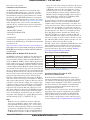
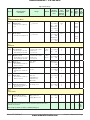
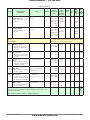
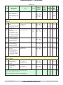
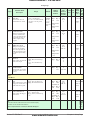
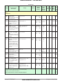
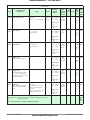
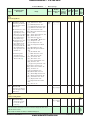
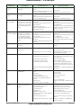
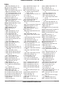
[`S;ti] Step Time Remaining 37, 38
[`StP] Active Step 37
[S;tyP] Active Step Type 37
[S;tyP] Step Type 55
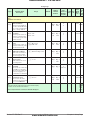
[t;Agr] User Tune Aggressiveness
45, 65
[t;bnd] TRU-TUNE+™ Band 45, 66
[``td] Time Derivative 34, 65, 70
[`t;gn] TRU-TUNE+™ Gain 45, 66
[``ti] Time 57
[``ti] Time Integral 34, 65, 70
[t;tUn] TRU-TUNE+™ Enable 45,
66
[`UFA] User Failure Action 45
[UloC] Unlock 74
[ULoC] Unlock 59
[UloC] Unlock Menu 74
[USr;r] User Restore Set 52, 65
[USr;S] User Save Set 52, 65
[UStP] Unused Step 58
[`W;E] Wait For Event 57
[WE;1] Wait Event 1 56
[W;Pr] Wait For Process 57
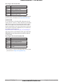
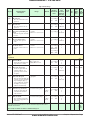
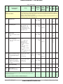
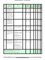
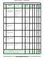
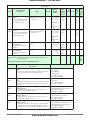
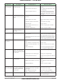
[AL`1] Alarm Error 79
[AL`2] Alarm Error 79
[`C;Er] Current Error 81
[Er;i2] Error Input 2 79
[Er;i1] Error Input 1 79
[`h;Er] Heater Error 81
[LiM] Limit Error 79
[``rP] Ramping 80
[tUNE] Autotuning 80
[uALU] 81
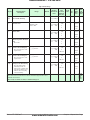
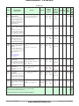
A
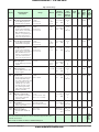
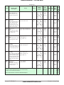
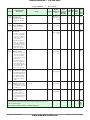
AC Line Frequency 52, 71
Active Event Output (1 or 2) 38
Active Step 37
Active Step Type 37
adaptive tuning 66
address
Modbus 26
Address Modbus 53
Address Standard Bus 53
Administrator Password 62, 74
agency approvals 3, 85
alarm blocking 73
Alarm Menu 35, 48
alarms 72
Blocking 49, 73
deviation 72
Display 50
Hysteresis 49, 72
Latching 49, 72
Logic 49
process 72
set points 72
Sides 49
Wat low EZ-ZONE ® ST
Silencing 49, 73
Source 48
Type 48
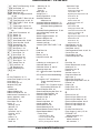
Alarm Type 72
analog input 4
Analog Input Menu 31, 40
Assembly Definition
Addresses 82
Assembly Definition Addresses 75
Assembly Definition Addresses and
Assembly Working Addresses
82
Assembly Working Addresses 75, 82
auto (closed loop) control 68
Autotune 65
Autotune Aggressiveness 45
Autotune Request 33
Autotune Set Point 33, 65
autotuning 65–66
autotuning with TRU-TUNE+™ 66
Baud Rate 53
Baud 26
Blocking 49, 73
bumpless transfer 68
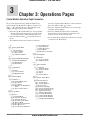
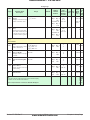
Operations Page
Alarm Menu 35
Analog Input Menu 31
Current Menu 36
Digital Input/Output Menu 32
Limit Menu 32
Loop Menu 33
Monitor Menu 32
Profile Status Menu 37
Setup Page
Alarm Menu 48
Analog Input Menu 40
Communications Menu 53
Control Loop Menu 44
Current Menu 50
Digital Input/Output Menu 42
Global Menu 52
Limit Menu 44
Output Menu 47
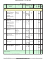
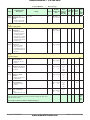
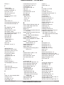
Cool Algorithm 44, 69
Cool Hysteresis 34, 69
Cool Power 33, 65
Cool Proportional Band 34, 65, 70
Current Error 36
Current Menu 36, 50
Custom Setup Menu 60
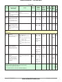
C
D
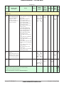
calibrating an analog input 67
Calibration Menu 63
Calibration Offset 31, 66–67
chattering output 69
CIP - Communications Capabilities
75
CIP Communications Methodology
29
CIP Implicit O to T (Originator to
Target) Assembly Structure
75, 84
CIP Implicit T to O (Target to Originator) Assembly Structure 84
Closed Loop Set Point 33
Closed Loop Working Set Point 33
Communication Protocols 28
Communications Menu 53
conceptual view 4
Control 42, 47
Control Loop Menu 44
control methods 68
Control Mode 33, 69
Control Mode Active 32
Control Module Factory Page 59
Control Module Menus
Factory Page
Calibration Menu 63
Custom Setup Menu 60
Diagnostics Menu 62
Security Setting Menu 60, 62
Data Map 53
Date of Manufacture 62, 63
dead band 70
Dead Band 34, 70
Decimal 42
deviation alarms 72
Diagnostics Menu 62
digital input 4
Digital Input Function 51
Digital Input/Output Menu 32, 42
Direction 42
Display 50
Display Pairs 52
Display Units 52, 53
B
• 90 •
www.anderson-bolds.com
E
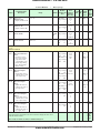
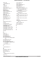
Electrical Gain 67
Electrical Input Offset 63, 67
Electrical Input Slope 63, 67
Electrical Measurement 63, 67
Electrical Output Offset 63
Electrical Output Slope 63
End 58
End Set Point Value 56
Event Output (1 and 2) 57, 58
EZ-ZONE™ ST
without contactor 6, 8
EZ-ZONE™ ST
without contactor 7
with contactor 7
Appendix