1
5.3 Calibration
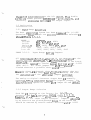
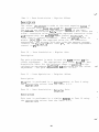
Input System Calibration
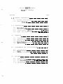
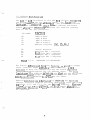
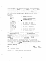
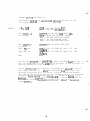
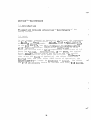
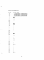
System Calibration is typically performed on a single channel
while running the following program. The program assumes
that the Polling Mode initialization has been
performed äs described in the Programming section.
AD:
AE:
AC:
AA:
AB:
AF:
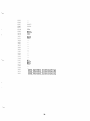
LD BC, OH
LD D, 64H
LD A, 0
OUT 88H, A
IN A, 89H
AND 01H
JP NZ, AC
IN A, 80H
LD L, A
IN A, 81H
LD A, L
SUB REF
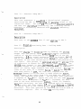
;LOAD ADDP. REG WITH CH. #
;IS CONVERSION COMPLETE?
;NO.
;YES. READ DATA
;IS DATA = LOW REF.?
;REF = OH FOR OFFSET ADJ.
REF = FFH FOR GIAN ADJ.
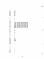
JP Z, AA
INC C
JP AB
INC B
DEC D
;NO. INCREMENT COUNT
;YES. INCREMENT COUNT
;HAVE 100 CONVERSIONS BEEN
;PERFORMED?
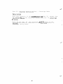
JP NZ, AE
JP AD
END
;YES. REPEAT
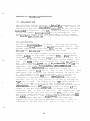
The program has been written to accommodate factory
preset addresses. If the board responds to other
addresses, the program references to I/O locations
must be made to conform with these new locations.
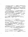
After assembling and loading, insert a breakpoint
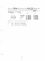
at location AF. The offset and gain adjustments
on the System are made while applying the voltages
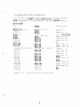
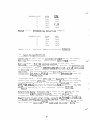
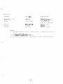
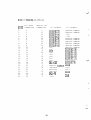
shown in Table 5.3.1. The offset voltage
adjustment is made at the most negative value of
the ränge, less 1/2 least significant bit
(LSB). An LSB is egual to the span (füll scale
ränge) divided by 4096 for 12-bit resolution. The
gain adjustment is made at the most positive ränge,
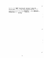
less 3/2 LSB. Thus, for a ränge of (+/-) 10V
18