1
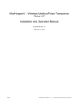
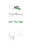
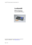
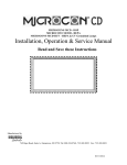
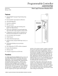
Timer Speed Control & Maintenance Monitor
Installation & User Manual
TSCMM
Read and Save these Instructions
Manufactured by
749 Hope Road, Suite A- Eatontown, NJ 07724 Tel: 800-224-9768, 732-389-8922 Fax: 732-389-8821
08/22/2013
08/22/2013
SAFETY INSTRUCTIONS
Read and Save these Instructions
Understanding the signal words: DANGER, WARNING and CAUTION.
These words are universally used for overall safety:
•
Signifies the most serious hazards, which will result in severe
personal injury or death.
•
Signifies hazards, which could result in personal injury or
death.
•
Signifies unsafe practices, which would result in minor
personal injury or product and property damage.
BEFORE INSTALLATION OR PERFORMING MAINTENANCE OR
SERVICE, TURN OFF THE MAIN HIGH VOLTAGE POWER BREAKER TO THE
UNIT. ELECTRICAL SHOCK CAN CAUSE INJURY OR DEATH. THERE MAY BE
MORE THAN ONE DISCONNECT.
READ INSTRUCTION MANUAL THOROUGHLY AND FOLLOW ALL
DANGER, WARNING OR CAUTION NOTES AND LABELS ATTACHED TO THE
UNIT BEFORE STARTING INSTALLATION OR MAINTENANCE ACTIVITIES.
IMPROPER INSTALLATION, ADJUSTMENT, ALTERATION, SERVICE,
MAINTENANCE, OR USE CAN CAUSE FIRE, ELECTRICAL SHOCK, OR OTHER
CONDITIONS THAT MAY CAUSE PERSONAL INJURY OR PROPERTY DAMAGE.
WEAR SAFETY GLASSES AND WORK GLOVES AND FOLLOW ALL SAFETY
LOCAL BUILDING AND ELECTRICAL CODES. CONSULT A QUALIFIED
INSTALLER, SERVICE AGENCY OR YOUR SUPPLIER FOR INFORMATION OR
ASSISTANCE.
08/22/2013
Table of Contents
Section:
Page
1.
TIMER SPEED CONTROL and MAINTENANCE MONITOR (TSCMM)......................... 4
2.
GENERAL MAINTENANCE INFORMATION .................................................................... 4
3.
TSCMM ELECTRICAL and MECHANICAL INSTALLATION......................................... 2
3.1.
3.2.
3.3.
3.4.
3.5.
3.6.
3.7.
3.8.
General Electrical Installation Instructions .......................................................................................... 2
Wiring Types and Gauges ...................................................................................................................... 2
Control Box Mounting............................................................................................................................ 2
Ground-Bond .......................................................................................................................................... 4
Retrofitting TCMM Controllers ............................................................................................................ 4
TSCMM 24VAC Power.......................................................................................................................... 6
TSCMM Control Wiring - AM Connectors........................................................................................... 6
TSCMM 24VAC Circuit Breaker and Circuit Overload Protection .................................................... 6
4.
TSCMM I/O, CONTROLS, INDICATORS and TROUBLESHOOTING ........................... 6
4.1.
4.2.
4.3.
4.3.1.
4.3.2.
4.3.3.
4.3.4.
4.3.5.
4.4.
4.5.
4.5.1.
4.6.
4.7.
4.8.
4.9.
4.10.
4.11.
4.12.
4.13.
4.14.
PWR “ON” LED .................................................................................................................................... 6
Manual Cycle Pushbutton ...................................................................................................................... 7
Blower Speed Control Options............................................................................................................... 7
Cycle Time Dial ...................................................................................................................................... 7
Set % Cycle @ High and %Med Speed Dials ....................................................................................... 8
System Speed LEDs ................................................................................................................................ 8
Individual Unit On LED......................................................................................................................... 8
Remote Run Inputs ................................................................................................................................. 8
Auxiliary Control Relay Contacts ......................................................................................................... 9
Reset Pushbutton and System “Stuck-Off”........................................................................................... 9
Remote Reset Input ................................................................................................................................ 9
Cycle-Mode Switch................................................................................................................................. 9
Zones 1-4 Inputs and LEDs Remote Activate (Initiate)......................................................................... 9
System “Stuck-On or Off” Situations .................................................................................................. 10
Timer Override Switches (Manual Run Continuously) ....................................................................... 11
Emergency Shut-Down Input ............................................................................................................... 12
“Emergency Stop” Alarm Output........................................................................................................ 12
Manual Shut-Down Slide Switch and LED.......................................................................................... 12
Check Filter LED and Filter Alarms.................................................................................................. 12
JP2 AUX ............................................................................................................................................... 13
5.
TSCMM SYSTEM SCHEMATIC EXAMPLE ........................................................................... 14
6.
SPECIFICATIONS................................................................................................................. 15
7.
OPTIONAL ACTIVATION EQUIPMENT .......................................................................... 15
7.1.
7.2.
7.3.
7.4.
7.5.
7.6.
7.7.
7.8.
7.9.
ACTIVATION EQUIPMENT LIST.................................................................................................... 16
Tone-Alarm Circuits............................................................................................................................. 16
Tone Alarm Wiring .............................................................................................................................. 16
Magnetic Door Relays .......................................................................................................................... 16
Gas Detector Circuits. .......................................................................................................................... 16
Custom Configurations ......................................................................................................................... 18
Electric Eye Circuits ............................................................................................................................ 18
Auto-Eject Power Disconnect or Vehicle Run Detector Systems ........................................................ 22
800 MHz Alert Systems ........................................................................................................................ 22
08/22/2013
1.
TIMER SPEED CONTROL and MAINTENANCE MONITOR
(TSCMM)
The standard TSCMM controller is offered in an 8.5” X 10.5” X 4” deep, hinged-door, NEMA4
rated, UL508 electrical enclosure. All of the TSCMM circuits operate at low voltage and low
energy levels. The TSCMM automatically controls the system activation run-time, and blower
motor speed of Biological Control air-filtration products. These include, but are not limited to,
AirMATION®, Airephase®, Airephase LE®, and MICROCON CD® units. The timer may be
activated manually or automatically. Some typical activation sources for the TSCMM are listed in
the Optional Activation Equipment section of this manual.
The TSCMM contains all of the wiring terminations necessary to interface up to eight (8)
individual filtration units.
The overall System Cycle-Time is set manually via a digital control dial mounted on the TSCMM
printed wiring board. Two (2) other dials are used to program three (3) motor speeds; each speed
set to run for a percentage of the total Cycle-time.
TSCMM CONTROLLER _DOOR OPEN
2.
GENERAL MAINTENANCE INFORMATION
Always remove power during any maintenance routine. Keep water away
from all electrical connections.
08/22/2013
The TSCMM requires no maintenance.
3.
TSCMM ELECTRICAL and MECHANICAL INSTALLATION
3.1.
General Electrical Installation Instructions
All electrical installation and maintenance must be performed by qualified
individuals and in accordance with the National Electrical Code, ANSI/NFPA 70-1999 and
local codes.
3.2.
Wiring Types and Gauges
Low Voltage control cables to and from the TSCMM use thermostat or alarm-control cabling.
Typical installations use unshielded 18-24gauge solid or stranded copper wire. Shielded twistedpair wire is used between master gas detector circuits and any optional remote-gas sensors (consult
the gas monitor manual).
The box shall contain only low voltage circuits.
Since the types of conduit, hardware and wiring practices vary widely, the wire access cutouts in
the box are not predrilled. The installing electrician will provide the proper cutouts to mount the
associated electrical hardware for wiring used for a particular installation.
3.3.
Control Box Mounting
The TSCMM is mounted on a wall by using the four mounting holes provided in the flange of the
NEMA box.
To prevent damage to components, the printed wiring boards must not be mounted inside the
enclosure during drilling procedures.
3.3.1.
Printed Wiring Board Installation/Removal
Employ Electro-Static Discharge (ESD) safety practices when handling the printed wiring boards
outside of the grounded enclosure.
3.3.1.1.
Voltage Regulator Cable Assembly
(See Schematic for Reference)
9 A Voltage Regulator Assembly is screwed to the inside wall of the enclosure to
effectively dissipate the device heat. A 3-wire cable connects it to the Parent PWB.
The regulator assembly cable must be detached from the box-wall before the
circuit-boards can be withdrawn from the enclosure.
9 Detach the 3-wire cable by removing the 6-32 nut holding the regulator to the box.
9 DO NOT REMOVE THE THERMAL GREASE from the box or component.
9 Remove four (4) 10-32 screws #1-4 shown in the diagram below.
9 Unfasten the Reset Pushbutton. Remove the large ¾”nut that holds the ResetPushbutton to the enclosure. Re-thread the nut onto the switch for safekeeping
until reinstallation takes place. The switch will remain connected to the circuit
board via two connecting wires.
9 Both boards (lower Parent and upper Child PWB) can now be removed from the
enclosure as a set. Put them aside in a safe place until all drilling or wire
maintenance operations are completed.
9 Reassemble the circuit boards into the enclosure in the reverse order. Reconnect
the regulator 3-wire cable to the side-wall using the 6-32 nut. Make sure the nut is
Copyright 2013 Biological Controls
Page 2
08/22/2013
tightened well and that some thermal grease is spread between the regulator
device and the box-wall (necessary for a good thermal connection).
Copyright 2013 Biological Controls
Page 3
08/22/2013
3.3.1.2.
PWB Separation
There is usually no need to separate the two PWBs for typical installations. If necessary for field
repair, follow the instructions on the diagram below.
Remove four (4) 6-32 nuts at positions #5 - #8. The connector force holding the two units
together is quite large. Wear gloves and use gentle but firm finger-pressure to separate the two
connectors (P1 and P2). Pull the boards apart gradually; alternating concentrated-pressure first at
one connector-end and then at the other. Pull the connectors only a few mm apart at any one time.
Alternate the pressure until the connectors separate. Do not use tools to separate the PWBs to
avoid damaging the PWB components. Follow the directions in the Diagram below for reassembly.
3.3.2.
Input/Output Connections
The TSCMM is equipped with euro-style terminal-strips to easily connect wiring to all of the
interfacing circuits. Mark the wires with tags to identify them for future reference and to help in
troubleshooting the connecting circuits.
Route all wires interfacing the TSCMM through the NEMA box wall by drilling appropriate size
holes that will mount cable bushings and or restraints per electrical codes. Leave sufficient slack in
the wires and make all of the necessary connections to the printed wiring boards. Use the schematic
inside the enclosure door or the manual to make the necessary wire connections. Neatly dress all
wires and cables to the inside walls of the box using cable-ties.
Use Silicone-Calk to fill the conduit openings (fill the conduit Aprox. 1”
deep) to prevent water condensation from entering the control box. If possible enter the box
from the side or bottom to avoid Condensation problems (water dripping across the PWBs).
3.4.
Ground-Bond
Check that the green-wire ground-bond connection of the NEMA enclosure
is properly connected to the facility-ground per code.
3.5.
Retrofitting TCMM Controllers
In most cases, upgrading an older TCMM system to a TSCMM is possible without having to
change the utility box, conduit or remove the box from the wall. The circuit-board mounting holes
are the same. Additional low voltage control-wires, when required, may be added by pulling them
through the original conduit or adding another entrance to the utility box. In most cases, an
additional two (2) wire cable to each motor (Filtration Unit) would be needed, but only when than
two (2) or more automatically programmed motor-speeds are required.
Install a #6-32 screw thru the box side-wall (lower left corner adjacent to the manual shut-down
switch) and attach the voltage regulator securely to the box using a 6-32 star-nut and thermal
grease .Make sure the nut is tightened well to provide good thermal contact with the box.
Copyright 2013 Biological Controls
Page 4
08/22/2013
Parent and Child PWB Shown Joined
Copyright 2013 Biological Controls
Page 5
08/22/2013
3.6.
TSCMM 24VAC Power
The 24VAC Power Module mounts on a standard wall-plug outlet. A retaining screw is used to
prevent it from becoming accidentally dislodged. The unit is equipped with a “power-on” LED.
The 24VAC output terminal screws on the power-module connect to the 24VAC input terminals
on the TSCMM. The power-module is provided in two sizes (40VA or 50VA) depending on the
total current requirements of the ordered system. Use 18-22 gauge bell or alarm-type wire for
connections to the Control Box.
3.7.
TSCMM Control Wiring - AM Connectors
The control cable run between individual filtration units and the TSCMM circuit-board are
terminated via 18-26 gauge wires. Keep these circuits separated from all high voltage circuits
within the facility. Refer to the schematic provided inside each TSCMM enclosure for specific
terminal or color-code information.
The AM1-8 “L” shaped connectors located across the top of the control board terminate the
control cables connected to the filtration blower modules. Each connector can be disconnected
(pulled-away) from the control box to access the connection-screws use to terminate each control
wire. The connectors snap-in and out with a firm but controlled-push or pull. A slight rocking
action usually helps dislodge the connection. Each is keyed so the connector can only be inserted in
one direction. Numbering the connector with tape or marker is encouraged to track the cable
to filtration unit association.
3.8.
TSCMM 24VAC Circuit Breaker and Circuit Overload Protection
A 2.5-Amp circuit-breaker (CB1) is used to protect the 24VAC input and 24VAC outputs of the
TSCMM. Check the “Power-on” LED to confirm that the pwb is operational. The Red LED
adjacent to the circuit-breaker “C/B TRIPPED” will light if the breaker trips.
The TSCMM internal 24VDC power circuits are protected with automatic-reset thermal-overload
devices. These will automatically reset after a brief wait if tripped by a fault condition. All 24VDC
output circuits are protected in a similar fashion.
4.
TSCMM I/O, CONTROLS, INDICATORS and TROUBLESHOOTING
All wiring going to and from the TSCMM enclosure and all circuits
within must be low voltage! Do not add auxiliary equipment or circuits on or within
the enclosure!
4.1.
PWR “ON” LED
This LED, located in the lower left corner of the Parent PWB near the manual shut-down
switch, is on whenever the unit is powered and operating normally or when in the manual
shut-down mode. If the green PWR “ON” LED is not lit use a volt meter to check for 24
volts AC at the 24VAC “in” terminals on the lower Parent-board. Make sure that
24VAC is also available at the 24VAC “out” terminals. Check the 2.5 Amp circuitbreaker to make sure it has not been tripped. If power is not detected, check the output of
the 24VAC transformer or power module and associated wiring. The 24VAC source is
always remote and not mounted on or within the TSCMM enclosure. Check the circuit
breaker assigned to the 24VAC power at the facility power panel.
Copyright 2013 Biological Controls
Page 6
08/22/2013
4.2.
Manual Cycle Pushbutton
Press the “CYCLE START” pushbutton mounted inside the TSCMM. The adjacent
green “Cycle” LED will light and remain on for the automatic cycle-time set on the timer
control dial. The Individual Unit IS LEDs will come for the duration of the cycle. If other
activation signals arrive after the push-button is pressed or is pressed multiple times, these
actions are ignored until the end of the cycle or a reset occurs.
Routine manual cycling should be done with optional buttons located outside of the
control box. Additional (remote) cycle push-buttons (simple push-buttons) wired back to
one of the Zone inputs of the controller may be used to manually start the system from
anywhere within the facility.
4.3.
Blower Speed Control Options
Blower motor-speed may be controlled only for Filtration Units that are equipped with
the optional “Green ECM Motors”
The”Green-motor” blower-modules may be wired for up to 6 speeds that can be
manually-selected at the blower module front panel. If equipped, the Speed-Rotary
switch can select one of three speeds, III, II, and I (CF Quiet Circulation). In addition, the
blower front panel may also be equipped with an optional ECO/Boost toggle-switch. This
toggle-switch determines one of two blower CFM ranges. Boost is the standard position
and ECO will run the motor proportionally slower in each of the Speed positions (see
Appendix in the Blower Motor section of the Filtration Manual for the speed vs. CFM
chart).
When a TSCMM controller is part of the system the Filtration Units equipped with a
rotary-speed control switch it must be placed in the “I “(CF) position. This will allow the
Controller to override the manual switch. The ECO/HI is selected based on the
customer’s specifications. The TCSMM can only override the ECO setting of the switch.
The TSCMM will automatically start, stop and set the blower-motor speeds for the
period of the programmed cycle-time or the duration of a manual override mode.
Note: The Green Motors start, stop and change speeds “softly” and do not require
power sequencing to avoid current surges. Some speed transition or ramp-times
may be 45 seconds or more.
4.3.1.
Cycle Time Dial
The Cycle-Time programs the overall system automatic cycling-period. The cycle time
dial is a 10 position rotary-switch (position number multiplied by 10 =minutes).
The Zero (0) position provides a programmed 5-minute test-cycle that disables all
automatic cycling. Press the Cycle Start pushbutton to initiate the test-cycle.
Do not leave the switch in the 0 position after testing because the system will not
respond to other Inputs.
Positions 1-9 are used for system automatic programming.
Position 1 sets a 10 minute cycle; Position 2 - for 20 minutes and so on; with position 9
being 90 minutes. A multiplier Jumper (JP4), when equipped, will multiply each positions
Copyright 2013 Biological Controls
Page 7
08/22/2013
1-9 by six (X6) times. Thus changing the standard cycle-time from an overall range of 10
minutes thru 90 minutes to 60 thru 540 minutes (1- 9 hours).
Optional-programming is available for customers with timing requirements that are
outside these ranges
4.3.2.
Set % Cycle @ High and %Med Speed Dials
The two (2) 10-position rotary-switches below the CYCLE-TIME dial determine the
percentage of time that the AM1-8 outputs will run at each of three (3) speeds (High,
Med, and Low (CF).
Divide the Cycle Time into percentages of time that the blowers will run at each speed.
For example, if the overall Cycle Time dial is set to 30 minutes, the HIGH Speed and
MED Speed dials are selected to run for 30% each (set the dial-position on each to 3 (dial
number x 10= 30 % of time). The system will default to the very low quiet circulate mode
(CF) for the remaining time of the cycle. In this example the blowers would run for
approximately 30% of the time at Hi; then 30% at Med; and the remainder of time at the
CF speed).
A second example shows how the blowers run at High for 30% and then very low (CF)
for the remainder of the cycle time (70%). The Set % @ high dial would be turned to #3
and the Set % @ MED dial would be turned to 0.
The typical factory cycle-time adjustments prior to shipping:
Cycle time is set to 40 minutes.
The % High and % MED speed dials are set to 3. This results in a 8 minute run in both
the HI and MED speeds and 24 minutes running at the LOW (CF) speed each time the
system is activated by one of the four (4) Zone inputs or a manual press of the cycle
pushbutton. The system will then return to any of the manual speed settings or shut-off.
4.3.3.
System Speed LEDs
The High, MED, and CF LEDs located to the left of the rotary-dial switches will come on
to indicate the blower speed changes as they occur. NOTE THAT THE LEDS WILL
FLASH IF THE PERCENTAGE OF TIME SELECTED IS GREATER THAN
100%. The controller will not respond to inputs until the proper % is set.
4.3.4.
Individual Unit On LED
A green LEDs associated with each of the AM outputs are located above the AM1-8
Output terminals running across the top of the board. These LEDs will come on anytime
an associated filter unit is powered either by the timer, an override switch or a remote run
signal.
4.3.5.
Remote Run Inputs
Filtration units connected to AM 1, AM3, AM5 and AM7 outputs may be remotely
controlled via inputs located on the far left bottom-corner of the printed wiring board.
A closure (short) across the terminal-strip screw-pairs will activate and associated output.
Typical applications have terminal-sets equipped with wires that go an Auxiliary daytimer or manual spring-return timer, thus enabling a single unit to run independently from
the others. The JP5 Jumper determines the motor-speed for the Remote Run mode. One
of two speeds may be selected by moving the jumper to cover two (2) terminals. The
Right -Position for low; and the Left-position for High (see schematic diagram). Note:
Copyright 2013 Biological Controls
Page 8
08/22/2013
Any automatic programming inputs will override these inputs. (After an automatic
cycle the units will return to the speed settings on the remote activate inputs.
4.4.
Auxiliary Control Relay Contacts
A Normally Open (NO), Normally Closed (NC) and a Common (C) relay contact are
available at a connector located to the far right edge of the Parent board (circuit-board on
the bottom). The Aux. relay contacts energize only when the TSCMM cycle timer is
activated.
These “dry contacts” must never be connected to control-circuits
containing voltages above 24 volts or currents above ½ amperes.
The relay may be used to operate low voltage control circuits needed to coordinate
other systems within a facility; i.e., turn-off facility air conditioner/heater/circulation fans.
The contacts may also be wired to a Remote By-Pass input of another TSCMM within a
facility to operate a filtration unit that may be designated as “common” to each controller.
It is not permitted to tie AM outputs of different TSCMM
controllers together to operate a “common” filtration unit.
4.5.
Reset Pushbutton and System “Stuck-Off”
The RED reset-button mounted on the outside of the utility box is used for routine
resets of automatic programmed cycles. Use the pushbutton to cancel any automatic
run-cycle. Additional buttons (bell push-buttons) may be added throughout the facility by
connecting a set of wires to the TSCMM Remote Reset terminals. Note that a any
malfunctioning reset button (i.e., broken return spring) can cause a stuck-off condition
such that the filtration system will not start until the fault is fixed. This button will not
reset manual-run switches or remote run switches.
4.5.1.
Remote Reset Input
May be used by auxiliary control circuits to prevent Zone 1-4 inputs or the manual Cycle
Start button from activating a TSCMM programmed cycle when terminals 1&2 are
shorted (external relay or switch closure) is connected to the inputs. Remote Run or the
various Manual Run switches will continue to work during a Remote Reset activation
period.
4.6.
Cycle-Mode Switch
This is a three-position switch.
4.6.1.
Top-Position: Run all units 24/7 at High Speed
4.6.2.
Middle-Position: Run all units 24/7 at Low Speed
4.6.3.
Bottom position: OFF (Automatic-Mode)
The 24/7 manual positions will be overridden by all automatic programming inputs, but the
Remote Run inputs or Manual Run switches will not be overridden. If Zone activation
signals (Zone 1-4) are received while the system is operating in the 24/7 mode, the system
will shift into the automatic program cycle and then return to the Manual 24/7mode after
the automatic cycle is completed.
4.7.
Zones 1-4 Inputs and LEDs Remote Activate (Initiate)
The four LEDs associated with the Zone Inputs come on only when an activation circuit
is sending a “closure” signal. If one or more of the Zone LEDs is “on” constantly (for
10sec or more) the Zone LED will begin to blink (See Zone 4 special condition below).
Copyright 2013 Biological Controls
Page 9
08/22/2013
The controller will run the filtration units for one (1) normal cycle but then lock-out the
“stuck” Zone input until it turns “Off “and then back “On”. This is not a normal situation
unless, for example, an auxiliary Day / Week Timer is tied into one of the Zone inputs, a
zone input source is intermittent or interrupting continuously, or a gas detector is sensing
unusually high concentrations of gas or is out of calibration.
If a “Zone” input LED is blinking, check the activation system tied to the associated
input. If all appears well, disconnect the wires to that Zone to make sure the LED goes
out. To check a “Zone” input, start with Zone 1, and short the two contacts with a wire.
The associated LED should light and bring on the timing cycle LED. Reset the
Programmed Cycle using the red reset push button mounted on the outside of the control
box and proceed to test the other “Zone” inputs in a similar fashion.
If all of the “Zone” inputs react properly when disconnected from the activation circuits,
the next step will be to disconnect all of the low voltage “Remote Activate” input wires
coming into the TSCMM “Zone” inputs at the terminal block. Mark the wires so that they
can be returned to the proper terminal locations. Note that several activation sources
may be wired in parallel and be brought to a single “Zone” input. These wire-sets when
disconnected (two from each source) should measure an “open-circuit” with an ohm
meter. (Never use an ohm meter across the TSCMM Zone terminal strip.) If a
“closed circuit” or “short” is detected, troubleshoot the reason for the continuous closure
at the offending activation source. Some common problems that cause continuous
closures are addressed below. The normal voltage measured across each pair of “Zone”
inputs (with no wires attached) at the terminal-strip is approximately 24VDC.
4.7.1.
Zone 4 (Gas Detector) Setup
When a gas detector circuit is connected to the TSCMM, jumper JP3 is equipped to make
the Zone 4 input fail-safe (cannot be locked-out). When equipped with JP3, Zone 4 will
not lock-out a continuous “closure” signal input and will run all filtration units until the
Zone 4 input signal goes away. This fail-safe mode is necessary since the normal condition
for a gas detector is to send a closure as long as gas or un-calibrated condition is detected.
Zone 4 can be used for other inputs that require a fail-safe mode (see section below and
Gas Detector wiring section) or Day timers that may provide a long-term closure and
locking out the input would not be a good thing.
4.8.
System “Stuck-On or Off” Situations
When the system continues to run after a normal timer cycle there is usually a “stuck”
activation source or one or more of the By-Pass switches or Remote Bypass ckts are
“turned-on”.
If the “remote-activate” inputs (Zones 1-4) are permanently “stuck-on” by an activation
source, all of the filtration units connected to the TSCMM will run for only one cycletime. The stuck activation source will then block the timer from starting another
automatic cycle from the offending source. Once cleared and the activation signal goes
away, the timer is free to begin a new automatic cycle. Any activation signals that may
arrive at one of the “Zone” inputs will restart the cycle at the beginning.
Note that once an activation source sends a “closure” to the controller, all of the filtration
units will run for the full time set on the timer control dial. During troubleshooting use
the Timer reset push-button to” Zero” the cycle time(restart) as often as is necessary.
A “Zone” input LED will remain on for as long as an activation source is sending a
“closure” signal. It is not normal for a Zone LED to remain on for long periods. If
Copyright 2013 Biological Controls
Page 10
08/22/2013
more than one activation-source is tied to a “Zone” input, remove the wires from each
activation source one set at a time until the offending system is identified.
Another possible problem might be an activation circuit that is sending sporadic closures
due to an electrical or mechanical problem (such as a chain waving in the breeze that
intermittently breaks a electric eye or a badly aligned electric-eye, etc.). The input signal
may not be constant but triggers often enough to prevent the timer from reaching the end
of the programmed cycle-time.
4.9.
Timer Override Switches (Manual Run Continuously)
The TSCMM provides one, 3-position manual control slide-switch for each filtration unit
output AM1-AM8.
In the “OFF”(Auto) position (normal condition) the TSCMM is under the automatic
programmed control of the internal timer and speed-control circuits normally triggered by
any of the optional sources connected to Zone 1-4 inputs.
In the 24/7 HI position the associated filtration unit will run continuously at the HI
blower speed.
In the 24/7 LOW (CF) position the associated blower unit will run continuously at Lowspeed).
The 24/7 speed select is overridden and returns to automatic programming when any of
the Zone 1-4 inputs are triggered. When the automatic programmed cycle is completed
the system will return to the Manual Mode inputs. The Override switches must be
returned to the “AUTO” position for the associated blowers to stop.
4.9.1.
Remote Run Inputs
A filtration unit within the system may be controlled via a remote manual switch, respond
to an auxiliary day-timer, or another TSCMM located away from the primary TSCMM.
The “REMOTE RUN” inputs may be used to remote-control up to 4 AM by providing a
“dry-contact” closure (short) across the associated Remote Run input terminals. A two
(2) terminal input-connector supports this function for four (4) of the AM odd-numbered
units (AM1, 3, 5, 7) and are located on the far left bottom-corner of the child-board.
The remote-run input for a particular unit will be overridden if any of the four (4) Zone
inputs or a manual “cycle” pushbutton initiates an automatic cycle.
Jumper, JP5, associated with the Remote-Run function allows the user to select one of
two speeds for the corresponding AM outputs. See the schematic diagram for speedpositions.
Copyright 2013 Biological Controls
Page 11
08/22/2013
4.10.
Emergency Shut-Down Input
The Emergency Shut-Down (fail-safe) input terminal is used by fire alarm or emergency
shut-down circuits to “turn-off” the TSCMM functions in the event of a fire or other
emergency. This input requires that JP1 is equipped when no fire alarm or emergency
shut-down circuits have been specified for a particular installation. If the jumper is
missing the TSCMM “Power-on” LED will be lit but neither the” Cycle On” nor the
individual “Unit ON” LEDs (above the by-pass switches) will come on. In addition, the
red emergency stop LED will light and no “Zone” input or manual-mode will enable the
filtration unit outputs (AM1-8).
Remove JP1 only when a fire or emergency shut-down circuit is connected to the
TSCMM Emergency Shut-Down input...
4.11.
“Emergency Stop” Alarm Output
This “dry-contact” relay output provides a continuity path for other emergency stop
circuits. It is employed when more than one controller is used within a facility. It is
necessary to cascade the alarm such that a shut-down in any one controller will stop the
filtration blowers in all.
The output may also be used for Facility Management Monitoring functions.
4.12.
Manual Shut-Down Slide Switch and LED
This switch does not remove high voltage circuits connected directly
to individual filtration units.
The switch is provided to temporally suspend the functions of the TSCMM controller. The
associated red LED will flash when the switch is in the “Shut-Down” position and the
controller functions will be suspended until the switch is returned to the “Normal” position.
Note that when Manual Shut-Down is active the system cannot react to any input
signals (including gas detectors).
4.13.
Check Filter LED and Filter Alarms
A yellow LED just below each AM output terminal lights when the “check filter” alarm of a
filtration unit is connected to the TSCMM. The LED indicates that filter maintenance is
required.
If any one of the eight (8) Check Filter LEDs is activated a large yellow Filter Alarm LED
will flash and the Optional Remote Filter Alarm output will be energized if equipped.
Note that if two filtration units are wired to share the same AM terminals (tandemconnection) the filter circuit cannot resolve the alarm to one unit. The filter alarm in the
control box will light if either one is in alarm. In addition, each of the filtration unit “check
filter” LEDs mounted on the respective chassis will light if either unit is in alarm.
An optional Remote Filter Alarm terminal strip is provided (located just below the
Remote Run Terminal strips) to connect the Filter Alarm Status to a remote display
or facility monitoring circuit.
It must be connected in a fashion that will isolate the TSCMM from all
currents sources other than the originating TSCMM.
The Remote Filter Alarm circuit provides a 24VDC - 100mA.maximum output.
Copyright 2013 Biological Controls
Page 12
08/22/2013
4.14.
JP2 AUX
Jumper JP2 located adjacent to the Zone 3 input terminals is reserved for future Custom
Programming functions. When this jumper is required it will be noted on the enclosure door
schematic. And this section of the manual will be updated.
Copyright 2013 Biological Controls
Page 13
08/22/2013
5.
TSCMM SYSTEM SCHEMATIC EXAMPLE
The schematic on the door of the TSCMM enclosure represents the wiring for that particular unit. Some of the
features and options depicted here may not have been ordered or wired.
Copyright 2013 Biological Controls
Page 14
08/22/2013
6.
SPECIFICATIONS
Power
Dimensions
Approvals
Timer Control (TSCMM)
Input Voltage- 24VAC @ 50/60Hz, 1Phase 330mA. Output Voltage- 24VAC +/- 5VAC 40VA
DC Control Signal outputs (AM1-AM8) 24VDC @~100mA each max.
Remote Filter Alarm output current: 24VDC - 100mA.maximum.
TSCMM Power Transformer:
Input -120VAC @ 50/60Hz, 1Phase Output - 24VAC +/- 5VAC @ 50/60Hz, 1Phase 40/50VA or
optional wall plug transformer with a 120VAC input @50/60Hz Output - 24VAC +/- 5VAC @
50/60Hz, 1Phase 40/50VA
8.5” X 10.5” X 4”, hinged-door
ETL US and Canada UL507, CSA C22.2 Enclosure: NEMA UL 508 Type 3R, 4, 12 and 13
Manufacturer: BIOLOGICAL CONTROLS 749 Hope Road, Suite A, Eatontown, NJ 07724
TEL: 800-224-9768 FAX:
732-389-8821
WEB SITE: www.biologicalcontrols.com
7.
OPTIONAL ACTIVATION EQUIPMENT
All electrical installation, troubleshooting and maintenance must
be performed by qualified individuals.
Although a filtration system may be activated manually by way of a simple wall switch or
permanently hard-wired to run 24/7, most installations incorporate an optional Timer Speed
Control and Maintenance Monitor (TSCMM) along with one or more optional activation sources
to automatically control the run-time of the filtration units. These application notes are provided to
help describe, install, and troubleshoot this optional hardware.
Every installation is, in a sense, “custom” because of the many variations in customer requirements
and working environments.
Rather than trying to cover every possible variation and
situation, a typical Fire/EMS Station environment is used to present examples and
fundamentals common to all installations. A thorough understanding of the interactions between
the Timer Controller and the various activation components is helpful to facilitate the installation
and necessary to effectively troubleshoot the optional equipment.
Fire Station installations require that the Diesel contaminates (particulates and gases) be cleared
from the air; both when the fire apparatus starts up before departing the station, and again when
returning to the building. Typically the run-time and blower-motor speeds of the filtration system is
programmed to address both the immediate gas and particulate contamination due to vehicle
exhaust and also the residual contaminates that remain after the vehicles are inactive. To
accomplish this, the units are electrically connected to a TSCMM. The controller will
automatically activate the filtration system for the cycle-time programmed by the customer. This
assures that any residual airborne contaminates or out-gassing sources, such as a cooling-down
engine or equipment and clothing contaminates brought into the facility can be cleaned to maintain
a healthful working environment. Depending on the building and/or the customer requirements, one
or more of the optional activation sources listed in the table below are used to start the controller
timer. A controller may be connected to gas monitoring hardware to check for precise levels of
certain gases, such as carbon monoxide (CO), nitrogen dioxide (NO2), hydrogen (H) and others,
that may be generated by sources not directly associated with the emergency vehicle engines. Some
examples might be normal or abnormal battery charging activity, auxiliary uses of the facility for
Copyright 2013 Biological Controls
Page 15
08/22/2013
community events or first response Homeland Security functions where people, equipment, or
vehicles not usually associated with the facility may affect the air quality.
7.1.
ACTIVATION EQUIPMENT LIST
TYPICAL TSCMM ACTIVATION SOURCES
AUDIBLE (TONE) ALARM CIRCUITS
MAGNETIC DOOR SWITCHES or Door Control Relays
INDUSTRIAL GAS DETECTORS
ELECTRIC EYE SYSTEMS
REMOTE INITIATE PUSH BUTTONS
AUTO-EJECT (Automatic Power Disconnect Systems)
800 MHz ALERT SYSTEMS
Local and Remote By-Pass Timers or Switches
Any System that provides “dry-contact” closure for activation
“dry contacts” – no external voltages present.
7.2.
Tone-Alarm Circuits
Tone-Alarm or Tone-Alert systems used in Fire Stations are designed to provide a variety of
audible and or electronic signals that help prepare the personnel and equipment to leave the
station for an emergency call. The tone alarm circuit in a Fire Station can provide a set of
“dry” relay contacts that close momentarily when the station Tone-Alarm sounds. This relay
should reset (go to the “open” position) in less time than the TSCMM timer controller run-time.
This activation source is desirable in some Fire Stations because it turns-on the filtration system
before any of the vehicles are started. Note that this installation will need one other activation
source connected to the controller to “turn-on” the filtration units when the vehicles return to
the station. Usually an electric eye system is employed.
7.3.
Tone Alarm Wiring
Wire the relay contacts from the tone alarm system that will provide a “closure on alarm” to
one of the Zone (“Initialize”) input terminals in the TSCMM. This relay should be dedicated to
the filtration system and not shared with other functions. See schematics in section 9 of the
Installation Manual. Use 18-24 gauge “thermostat wire” or equivalent control cable for this
low voltage connection.
7.4.
Magnetic Door Relays
Relay placement is designed to activate a TSCMM as soon as a door starts to move; either
when opening or closing. To cover both conditions two (2) magnets and one switch may be
used on conventional roll-up or curtain door systems. Where the doors are hinged along the
edges and open “out” in sets or slide from side-to-side and meet in the middle, the same
principles apply and sometimes an actuator (relay) is added to the door electrical controller to
activate the TSCMM. Contact Biological Controls for application notes detailing the circuits
and the positioning of the magnetic relays or associated hardware.
7.5.
Gas Detector Circuits.
The optional Gas Detection hardware available thru Biological Controls is used in conjunction
with the TSCMM to provide a safe working environment. Some installation specifications
require that the filtration units turn on at a certain concentration level of Carbon Monoxide or
Nitrogen Dioxide. The primary sources of CO and NO2 are motor vehicles, electric utilities,
and other industrial, sources that burn fuels.
Copyright 2013 Biological Controls
Page 16
08/22/2013
The Industrial-grade gas detectors provided by Biological Controls can sense very precise
concentration levels of many gases (see table below) and provide two programmable levels of
alarm. The first alarm level will start the filtering system when a very low, but abnormal level of
a particular gas is detected. The second level activates an audible alarm to alert personnel to a
more dangerous situation. Usually the filter units remedy the situation such that the second
level is never reached. A programmed detector-delay of at least 60 seconds is suggested for
most applications to bridge brief incidents that might trigger the system prematurely. These
would include sporadic power surges, radio interference or momentary surges in gas levels.
Each detector also provides a visual display to indicate the concentration levels of the particular
gas in the vicinity of the unit. The gas detected along with the factory-set alarm points are
labeled on each detector. Dual-gas monitor units are available so that two gases can be
monitored with a single unit. The TSCMM will continue blower activation for one
additional timer-cycle after the gas levels have moved several ppm under the alarm setpoints.
Typical Gas Detection List:
Ammonia
Acetylene
Butane
Carbon Dioxide
Carbon Monoxide
Chlorine
Diesel
Ethylene
Hydrocarbons (light & heavy)
Hydrogen
Hydrogen Chloride
Hydrogen Cyanide
Hydrogen Sulfide
Methane
Methanol
Methyl Ethyl Ketone
Nitrogen Dioxide
Nitrogen Oxide
Oxygen
Propane
Refrigerants
Sulfur Dioxide
7.5.1.
Gas Detector Wiring to the TSCMM
The “normally-open” (NO) and “common” (C) relay contacts on the first level alarm output
(Relay A) are wired to Zone 4 input. Jumper JP3 is equipped to make sure that a
continuous closure will run the Activation system in a “Fail-Safe” mode (run
continuously until the gas detector signal turns off).
In addition most gas detectors can be programmed for “fail-safe” operation. The “fail-safe
mode” will sense when power is lost to the detector and the alarm relay will close. When
operating in the “fail-safe mode” the “normally- closed” (NC) and the “common” (C) relay
contacts must be connected to the TSCMM Zone 4 with jumper JP3 equipped. In all cases, the
Gas Detector relay contacts chosen should always present an open-circuit when the gas levels
are near Zero (less-than the programmed set points… typically <24ppm of CO and < .6ppm of
NO2.) The Zone LED in the TSCMM box associated with the gas detector wiring should
normally be off. If not the filtration system will run continuously. See the Gas Detector User
Manual shipped with each unit for terminal and relay connector information.
The gas detector hardware may be powered by one of the TSCMM 24VAC power supply
outputs or another 24VAC/DC source. See section 9.3 in the Installation Manual.
Connect 18-22 gauge wires from the 24VAC output terminals in the TSCMM to the 24VAC
input terminals of the gas detector unit. Several detectors may be wired in parallel to power an
array when several units are needed to monitor areas larger than the normal 50 foot coverage
radius. Optional 24VAC wall plug-in power supplies are also available when it is more
convenient to provide individual unit power. These optional power supplies plug into a normal
115VAC outlet. 18-22 gauge wires are then run from the transformer to the 24VAC inputs of
the gas detector. A dual–gas detector unit will have one sensor in the base unit and one
Copyright 2013 Biological Controls
Page 17
08/22/2013
mounted remotely and connected together with a twisted, shielded, 24 gauge cable (e.g.,
Olympic Wire & Cable #9600).
7.5.2.
Gas Detector Positioning
The optimum installation location for the gas detector hardware is different for each of the
gases listed in the tables below (e.g., height off the floor). This information is included in the
gas detector package.
Gas
Carbon Monoxide (CO)
Nitrogen Dioxide (NO2)
Sulfur Dioxide (SO2)
First Level
Alarm Set-point
25ppm
. 7ppm
2pp
Second Level
Alarm Set-point
200ppm
2ppm
5pp
Sensor Location
Detection
Radius
3-6’ above the floor
50’
1 foot below ceiling
50’
1 foot above floor
20’
ppm (parts per million)
7.5.3.
Gas Detector Calibration:
Calibration of the units should be performed according to the gas detector manual. The
replaceable gas sensors used in this product will last for approximately 3 years before they need
to be changed. Maintenance contracts or calibration kits may be purchased through the gas
detector manufacturer or distributor.
7.6.
Custom Configurations
Custom configurations exist to meet special requirements. Always check the schematic on the
enclosure door of the TSCMM before installation or troubleshooting.
7.7.
Electric Eye Circuits
Blocked or Misaligned photo-eyes will cause the activation system to “lock-out” those inputs
until the problem is cleared. The system will not react to the signal until proper alignment is
achieved. (Note: Older TCMM controllers will run the filtration units continuously until
alignment is corrected.
Electric Eye Circuits are utilized in many facilities where a momentary interruption of the light
beam will start the filtration system. The electric eye equipment resolves the situation where
vehicles are returning to a Fire/EMS station; the doors are already open, and the filtration units
are off. Each time the chassis of a vehicle breaks the light beam the TSCMM will restart the
cycle-time of the filtration system. In this case the Fire Station doors need not move to turn on
the system. To make the electric eye system better, mechanical “flags” (L-brackets included
with the option) are attached to the bay doors and positioned to interrupt the light beam
whenever the doors are operated. This entire system assures that the filtration units will come
on anytime the doors open, close and when a vehicle passes through the bay. The light beam is
positioned high enough to prevent activation by people passing in and out of the bay doors. See
figure 13J and 13K.
In all electric eye installations the light beam should not be blocked for long periods of time
since the electric eye relay will “lock-up” the controller timing circuits and the filtration system
will not run until the signal is reset (turns off and then back on again). If the activity at a
particular facility is such that blocking the eye- beam for long periods is normal, a separate
Zone should be dedicated to this bay.
Copyright 2013 Biological Controls
Page 18
08/22/2013
The most popular electric eye hardware used currently is set up with a transmitter and receiver.
The transmitter(Q453E) has one (1) status LED and two (2) wire connections (brown and
blue) and the receiver (Q45VR3R) has three status LEDS (3) and five (5) wires (brown, blue,
yellow, white and black) to connect to the TSCMM. The brown and blue wires for both are
used to power the respective units using the TSCMM 24VAC output terminals as shown in the
schematic below. The normally closed (NC) relay contact and the common (C) relay contact in
the receiver are white and yellow. The black wire (NO) is not used. It should be noted that the
color code could be changed over time or is not the same for other vendors so always refer to
the schematic drawn on the hardware to double check the wiring.
The single green LED on the transmitter (Light source) indicates that the unit is powered
properly.
The receiver also has a green LED to indicate proper power. The red LED will pulsate when it
“sees” the transmitter light source. As the alignment between the transmitter and receiver
improves so does the pulse rate of the red LED. When the alignment is very good the pulse
rate will be so fast as to make the red LED look like it is fully on. When the red LED is off and
the green LED is on, the receiver is not aligned properly or the transmitter is not providing
light. Align the transmitter and receiver such that the red LED is pulsing very rapidly or appears
to be solidly on.
The yellow status LED will be on to indicate that the relay contacts are activated when proper
alignment is achieved. In this case the yellow and white wires will provide an “open contact”
when the system is in alignment. By blocking the light path with a vehicle, a mechanical door
flag, your hand (for testing purposes) will cause both the red and yellow LEDS to go out. This
action closes the relay contacts attached to the yellow and white wires, which in turn, activate
the TSCMM remote-activate input and turns on the filtration system.
In facilities where two or more similar electric eye systems are in use for different functions,
make sure that the light source for the other systems does not interfere with the filtration
system. Since the polarized-light beam is wide it may not be possible to have two light system
receivers in close proximity to each other. When interference has occurred between two
systems in the past, simply reversing the location of the transmitter and receiver solved the
problem. In other words, make sure that the transmitters (light sources) for the two systems are
positioned on opposite sides of the door. With this configuration the receivers in each system
will only “see” the proper light source.
Copyright 2013 Biological Controls
Page 19
08/22/2013
7.7.1.
Single Electric Eye System
A single electric eye system may be employed to cover multiple bay configurations where no
walls or obstructions will interfere with the single light beam. The wiring for a single eye
system is shown in the figure below.
Single Electric Eye Diagram
Copyright 2013 Biological Controls
Page 20
08/22/2013
7.7.2.
Multiple Electric Eye System
Where walls or obstructions exist multiple electric eyes are used to control the TSCMM.
Multiple Electric Eye Schematic
Multiple Electric Eye Diagram
Copyright 2013 Biological Controls
Page 21
08/22/2013
7.7.3.
Flag (Beam Interrupter) Mounting and Positioning
(Side-view)
7.8.
Auto-Eject Power Disconnect or Vehicle Run Detector Systems
Some facilities incorporate an electrical charging system to maintain batteries on the vehicles
while they are parked. The power cords attached to the vehicles are automatically ejected
when the ignition switch in the vehicle is turned on. Many of these systems have an optional
transmitter that is also attached to the ignition system of the vehicle.
The receiver mounted in the facility contains several dry-contact relays that are used to activate
anything from over-head doors, traffic light systems, tone alarms, and or blower systems. The
Kussmaul system is an example of equipment used to detect a running engine.
One of the relays provided in the optional system receiver should be dedicated (not shared with
any other circuit) to activate one of the Zone inputs of the TSCMM. The relay contact must
provide a “closure-on-signal” to the controller.
7.9.
800 MHz Alert Systems
Fire Stations may use a special 800 MHz radio signal sent by the 911 emergency services or
other sources to alert the facility. The radio receiver for this system incorporates relays that are
used to activate systems in the Fire/EMS Station in preparation for an emergency. One of the
relays in the 800 MHz receiver should be used to connect to one of the Zone inputs of the
TSCMM.
Copyright 2013 Biological Controls
Page 22
08/22/2013