1
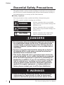
Flex Network Analog Unit User Manual Digital Electronics Corporation Preface Preface Thank you for purchasing Digital Electronics Corporation's Flex Network analog (AD Conversion / DA Conversion) units, hereafter referred to as the "Unit". The unit is designed to be used with Pro-face’s Graphical Logic Controller (GLC) Series, LT Series, and GP3000 Series FLEX NETWORK board type (hereafter referred to as “GLC”) as a remote I/O system. This manual explains the overall features and specifications of the Unit, as well as its installation procedures. Please be sure to read this manual thoroughly to understand the correct and safe usage of this product and its features. Flex Network analog (AD Conversion / DA Conversion) units (FN-AD04AH11/ FN-DA04AH11) are not CE marked, UL/c-UL (CSA) listed products. <Note> 1) It is forbidden to copy the contents of this manual, in whole or in part, except for the user's personal use, without the express permission of the Digital Electronics Corporation of Japan. 2) The information provided in this manual is subject to change without notice. 3) This manual has been written with care and attention to detail; however, should you find any errors or omissions, please contact the Digital Electronics Corporation and inform us of your findings. 4) Please be aware that Digital Electronics Corporation shall not be held liable by the user for any damages, losses, or third party claims arising from the uses of this product. All Company/Manufacturer names used in this manual are the registered trademarks of those companies. © Copyright 2000 Digital Electronics Corporation FLEX NETWORK® is a registered trademark of Digital Electronics Corporation in Japan and other countries. Flex Network Analog Unit User Manual 1 Preface Table of Contents Preface ........................................................................................................................ 1 Table of Contents ...................................................................................................... 2 Essential Safety Precautions ................................................................................... 4 Documentation Conventions .................................................................................... 6 Flex Network Unit Models ....................................................................................... 6 Compatible GLC Units ............................................................................................. 7 Driver ......................................................................................................................... 7 CHAPTER 1 INTRODUCTION 1.1 System Design ............................................................................................. 1-1 1.2 Accessories .................................................................................................. 1-3 CHAPTER 2 2.1 SPECIFICATIONS General Specifications ............................................................................... 2-1 2.1.1 Electrical .......................................................................................... 2-1 2.1.2 Environmental ..................................................................................... 2-1 2.1.3 Structural ............................................................................................ 2-2 2.2 Performance Specifications ....................................................................... 2-2 2.2.1 Data Transfer Settings ..................................................................... 2-2 2.2.2 Flex Network Analog Unit Input/Ouput .......................................... 2-3 2.3 Analog Characteristics ............................................................................... 2-4 2.4 Analog/Digital Conversion ......................................................................... 2-5 2.5 4-Channel Analog Unit Wiring ................................................................... 2-6 2.6 Part Names and Features .......................................................................... 2-8 2.6.1 2.7 4-Channel Analog Unit Part Names and Features ........................... 2-8 Dimensions ................................................................................................ 2-14 2.7.1 Analog Unit Dimensions ................................................................ 2-14 CHAPTER 3 INSTALLATION AND WIRING 3.1 Installation ................................................................................................... 3-1 3.1.1 3.2 2 Installing / Removing the Analog Unit .............................................. 3-1 Wiring ........................................................................................................... 3-3 3.2.1 Using the Flex Network Communication Cable .............................. 3-3 3.2.2 Power Cord Wiring ......................................................................... 3-6 3.2.3 I/O Cable ........................................................................................ 3-6 3.2.4 Cautions When Wiring Communication Lines .................................. 3-7 Flex Network Analog Unit User Manual Preface CHAPTER 4 PROBLEMS AND SOLUTIONS 4.1 Prior to Troubleshooting ........................................................................... 4-1 4.2 Error Code Display .................................................................................... 4-2 4.3 Troubleshooting for GLC2000/LT Series ............................................... 4-3 4.4 4.5 4.3.1 Troubleshooting Checklist for GLC2000/LT Series .................... 4-3 4.3.2 Error Code List for GLC2000/LT Series ...................................... 4-4 Troubleshooting for GP3000 Series ........................................................ 4-5 4.4.1 Troubleshooting Checklist for GP3000 Series ............................ 4-5 4.4.2 Error Code List for GP3000 Series .............................................. 4-6 After-sales service ...................................................................................... 4-8 Flex Network Analog Unit User Manual 3 Preface Essential Safety Precautions This guide contains a variety of safety markings for safe and correct operation of this Unit. Please read this installation guide and any related manuals carefully to fully understand how to correctly use this Unit's functions. Safety Symbols Please pay attention to these symbols and follow all instructions given. The safety symbols and their meanings are as follows: DANGER Indicates situations where severe bodily injury, death or major machine damage will definitely occur. WARNING Indicates situations where severe bodily injury, death or major machine damage can possibly occur. CAUTION Indicates situations where slight bodily injury or machine damage can occur. DANGERS • An emergency stop circuit and an interlock circuit should be constructed outside of this Unit. Constructing these circuits inside a system that uses this Unit may cause a runaway situation, system failure, or an accident due to unit failure. • Systems using this Unit should be designed so that output signals which could cause a serious accident are monitored from outside the Unit. • This Unit is designed to be a general-purpose device for general industries, and is neither designed nor produced to be used with equipment or systems in potentially lifethreatening conditions. If you are considering using this Unit for special uses, including nuclear power control devices, electric power devices, aerospace equipment, medical life support equipment, or transportation vehicles, please contact your local Pro-face distributor. WARNINGS • Prior to installing, removing, wiring, and conducting maintenance or inspections, be sure to disconnect power to this Unit to prevent an electric shock or fire. 4 Flex Network Analog Unit User Manual Preface WARNINGS • Do not disassemble or remodel this Unit, since it may lead to an electric shock or fire. • Do not use this Unit in an environment that contains flammable gases since an explosion may occur. • Do not use this Unit in an environment that is not specified in either the Installation Guide or the User Manual. Otherwise, an electric shock, fire, malfunction or other failure may occur. • Due to the possibility of an electric shock or malfunction, do not touch this Unit's power terminals while it is operating. CAUTIONS • Communication cables or I/O signal lines must be wired separately from the main circuit (high-voltage, large-current) line, high-frequency lines such as inverter and power lines. Otherwise, a malfunction may occur due to noise. • This Unit must be installed according to directions given in the Installation Guide and the User manual. Improper installation may cause the Unit to malfunction or fail. • This Unit must be wired according to directions in the Installation Guide and the User Manual. Improper wiring may cause a malfunction, failure or electric shock. • Do not allow foreign substances, including chips, wire pieces, water, or liquids to enter inside this Unit's case. Otherwise, a malfunction, failure, electric shock, or fire may occur. • When disposing of this Unit, it should be processed according to your country's industrial waste disposal laws. To Prevent Unit Damage • Avoid storing or operating this Unit in either direct sunlight or excessively dusty or dirty environments. • Because this Unit is a precision instrument, do not store or use it in locations where strong shocks or excessive vibration may occur. • Avoid covering this Unit's ventilation holes, or operating it in an environment that may cause it to overheat. • Avoid operating this Unit in locations where sudden temperature changes can cause condensation to form inside the Unit. • Do not use paint thinner or organic solvents to clean this Unit. Flex Network Analog Unit User Manual 5 Preface Documentation Conventions The list below describes the documentation conventions used in this manual. Symbol Meaning Indicates important information or procedures that must be followed for correct and risk-free software/device operation. *1 1) , 2) Indicates useful or important supplemental information. Indicates steps in a procedure. Be sure to perform these steps in the order given. Refers to useful or important supplemental information. Provides useful or important supplemental information. GLC Generic name for the "GLC Series" of Graphic Logic Controllers made by Pro-face. In this manual, it also indicates "LT Series" and "GP3000 Series FLEX NETWORK board type". Flex Network Unit Models Flex Network Units allow the GLC to communicate via a Flex Network system. The different Flex Network Unit model numbers are shown below. Product Family Flex Network 6 Unit Name Nodes Required Model No. FN-X16T S41 FN-X32T S41 FN-Y16SK41 FN-Y16SC41 I/O Unit FN-XY08TS41 FN-XY16SK41 FN-XY16SC41 FN-XY32SKS41 FN-Y08RL41 FN-AD02AH41 FN-DA02AH41 Analog Unit FN-AD04AH11 FN-DA04AH11 FN-PC10SK41 Single-Axis Positioning Unit FN-PC10LD41 1 2 1 1 1 1 1 4 1 1 1 4 4 4 - High-Speed Counter Unit FN-HC10SK41 8 Manual DIO Unit User Manual 2-Cannel Analog Unit User Manual This Manual Single-Axis Positioning Unit User Manual High-Speed Counter Unit User Manual Flex Network Analog Unit User Manual Preface Compatible GLC Units The following GLC units can be used with the Flex Network units. (GLC, LT , and GP are referred to collectively as the “GLC” in this manual.) Product Family Series Name GLC2300 Series GLC2400 Series GLC GLC2000 Series GLC2500 Series GLC2600 Series LT LT Series GP-3300 Series GP-3400 Series GP GP3000 Series GP-3500 Series GP-3600 Series Unit Name Model No. GLC2300T GLC2300L GLC2400T GLC2300-TC41-24V GLC2300-LG41-24V GLC2400-TC41-24V GLC2500-TC41-24V GLC2500T GLC2500-TC41-200V GLC2600-TC41-24V GLC2600T GLC2600-TC41-200V LT TypeB GLC150-BG41-FLEX-24V LT Type B+ GLC150-BG41-XY32KF-24V LTC Type B+ GLC150-SC41-XY32KF-24V LT Type C GLC150-BG41-RSFL-24V AGP-3300L AGP3300-L1-D24-FN1M AGP-3300T AGP3300-T1-D24-FN1M AGP-3400T AGP3400-T1-D24-FN1M AGP3500-T1-D24-FN1M AGP-3500T AGP3500-T1-AF-FN1M AGP3600-T1-D24-FN1M AGP-3600T AGP3600-T1-AF-FN1M Driver The driver for the Flex Network Unit is required in order to use the unit. For GLC2000 series and LT series, You can select the Flex Network Driver via GP-PRO/PBIII C-Package (Pro-Control Editor) or LT Editor. If the selection of the appropriate unit's name does not appear in the [I/O Configuration] - [I/O Unit Settings] area, you will need to update the driver file. You can download the latest driver from Pro-face's web site. URL :http://www.pro-face.com/ For GP3000 Series, You can select the Flex Network Driver via GP-Pro EX as an I/O driver. Flex Network Analog Unit User Manual 7 Memo Flex Network Analog Unit User Manual 8 1. System Design Chapter 1 2. Accessories Introduction The Analog/Digital Conversion Unit (FN-AD04AH41) converts an analog signal to a 12-bit digital signal, and then inputs the signal to a GLC unit. The Digital/Analog Conversion Unit (FN-DA04AH41) converts the GLC unit's internally processed 12-bit digital to analog output. This chapter explains the standard system design for the Flex Network unit, and the types of units available. 1.1 System Design The following information explains how to connect the GLC to a Flex Network Unit. When connecting the Flex Network unit, 2 channels are available - CH1 and CH2. Each channel outputs the same data and either can be used for data transmission. The maximum number of connectable units, when using a single channel, is 31, and when using a second channel, the number increases by 32 to a total of 63. • Units can be connected at the above number of connectable units when one unit (16 bits) occupies a single Flex Network unit. In case of an analog unit, each AD / DA conversion unit occupies 4 units (64 bits). • The Flex Network uses high speed data transfer technology, and if a is cable used for data transfer that is not the same as that specified in this document, network data transfer performance cannot be guaranteed. Thus, be sure to use only the cable(s) recommended here. 3.2.1 using the Flex Network Communication Cable With One (1) Channel Flex Network Unit GLC Flex Network I/F Maximum cable length: 200m (6Mbps) 100m (12Mbps) Maximum No. of Units: 31 Flex Network Analog Unit User Manual 1-1 Chapter 1 - Introduction With Two (2) Channels Flex Network Unit CH1 GLC Flex Network I/F CH2 Maximum cable length: 400m (6Mbps) 200m (12Mbps) Maximum No. of units: 63 (31 + 32) When 2 channels are used, one of each channel can be connected with up to 32 units. Standard System Design AD Conversion Unit 16 Input Points Unit DC24V GLC Sensor Operation Switch 8 points Input/ 8 points Output Unit DC24V From Analog Output Unit DA Conversion Unit Valve Actuator Lamp Sensor Operation Switch DC24V to next station *1 DC24V To Analog Input Unit to next station *1 • 6Mbps is the recommended speed. *1 Be sure the Terminal Switch (TERM) of the network's last unit (at each end) is turned ON. 1-2 Flex Network Analog Unit User Manual Chapter 1 - Introduction 1.2 Accessories All optional equipment listed here is sold separately. Optional Items Item Model No. FN-CABLE 2010-31-MS (10m) Flex Network Communication Cable FN-CABLE 2050-31-MS (50m) FN-CABLE 2200-31-MS (200m) Flex Network Analog Unit User Manual Description Connect GLC units with Flex Network units. 1-3 Memo Flex Network Analog Unit User Manual 1-4 1. 2. 3. 4. 5. 6. 7. Chapter 2 2.1 General Specifications Performance Specifications Analog Characteristics Analog/Digital Conversion 4-Channel Analog Unit Wiring Part Names and Features Dimensions Specifications General Specifications 2.1.1 Electrical Control Section Items Rated Voltage Input Voltage Allowable Voltage Drop In-Rash Current Power Consumption Voltage Endurace Insulation Resistance FN-AD04AH11 FN-DA04AH11 DC24V DC20.4V to DC28.8V Up to 10ms (Power Supply:DC24V) 30A or less 4.8W or less 7.2W or less AC1500V 10mA for 1min. (between input/output and FG terminals) AC500V 1min. (between power supply 1st Level and 2nd Level) 10M Ω or higher at DC500V (between charging and FG terminals) 2.1.2 Environmental Ambient Operating T emperature Ambient Storage T emperature Ambient Humidity Atmosphere Corrosive Gas Vibration Endurance Noise Endurance (via noise simulator) Electrostatic Discharge Immunity 0oC to 55oC -20oC to +70o C 30%RH to 95%RH (no condensation) level RH - 1 Free of dust (less than 0.1mg/m 3) No corrosive gasses 5Hz to 55Hz 60m/s2 (in X,Y,Z directions for 3 times each) Noise Voltage: 1000Vp-p Pulse Width: 1ms Rise T ime: 1ns Contact Discharge, (IEC61000-4-2, Level 3) 2.1.3 Structural Attachment Method Cooling Method Weight External Dimensions Rating Flex Network Analog Unit User Manual via 35 mm DIN rail or by attachment screws Natural air circulation Less than 350g W168 mm [6.61 in.] x H50 mm [1.97 in.] x D50 mm [1.97 in.] IP30 2-1 Chapter 2 - Specifications 2.2 Performance Specifications 2.2.1 Data Transfer Settings GLC2000/LT Series GP3000 Series Communication T ype Connection Method T ransfer Distance 1:N Multi Drop At 6Mbps 200m per CH, at 12Mbps100m per CH Transfer Method During cyclic period, distributed transmission, Half-duplex T ransfer Speed T ransfer I/F Error Check 6Mbps, 12Mbps Differential method, Pulse transfer resistance Format check, bit check, CRC-12 check 63 stations max., Bit variable input: 256 points, 63 (max.), 1008 I/O points Bit variable output: 256 points, (depending on type of units used.) Integer variable input: 64 points, Integer variable output: 64 points (depending on type of units used.) No. of Stations 2.2.2 Flex Network Analog Unit Input/Ouput Analog Input Section (FN-AD04AH11) Resolution Number of Input Channel Conversion T ime Input Range Input Range Switch Calibration Function Accuracy Insulation Method Processing (after conversion) Conversion T iming 2-2 12 bit 4ch (fixed) up to 2 milliseconds 0 to 5V (Impedance 1M Ω ) 1 to 5V (Impedance 1M Ω ) 0 to 10V (Impedance 1M Ω ) -5 to 5V (Impedance 1M Ω ) -10 to 10V (Impedance 1M Ω ) 0 to 20mA (Impedance 200Ω ) 4 to 20mA (Impedance 200Ω ) Depends on rotary switch settings OFFSET , GAIN Setting Setting the upper limit value / lower limit value for each range via switch 0.3% / FS (25 oC) 0.5% / FS (0o C to 25o C) Photocoupler Insulation (input terminals / between internal circuits) Simple Average, Running Average Exclude Max. / Min. values Simultaneous - all channels (not selectable) Flex Network Anaolg Unit User Manual Chapter 2 - Specifications Analog Output Section (FN-DA04AH11) Resolution Number of Output Channel Conversion T ime Output Range Output Range Switch Calibration Function Accuracy Insulation Method Conversion T iming 12 bit 4ch (fixed) Up to 2 milliseconds 0V to 5V (Impedance 1KΩ ) 1V to 5V (Impedance 1KΩ ) 0V to 10V (Impedance 1KΩ ) -5V to 5V (Impedance 1KΩ ) -10V to 10V (Impedance 1KΩ ) 0mA to 20mA (Impedance 400Ω ) (*1) 4mA to 20mA (Impedance 400Ω ) (*1) Depends on rotary switch settings OFFSET , GAIN Setting Setting the upper limit value / lower limit value for each range via switch 0.3% / FS (25 o C) 0.5% / FS (0 o Cto 55 o C) Photocoupler Insulation (output terminals / between internal circuits) Convert all channels at all time (not selectable) *1 : For continuous output to 4 channels at the same time with FN-DA04AH11, the output current for 1 channel should be 10mA or less. Or, the total current of all channels should be 40mA or less. Flex Network Analog Unit User Manual 2-3 Chapter 2 - Specifications 2.3 Analog Characteristics This section explains the Flex Network unit Analog Characteristics. Digital Input/Output Values Voltage (V) 0V to 5V 1V to 5V 0V to 10V -5V to 5V -10V to 10V 1 2 3 4 -2047 -5.0 -10.0 Analog Input/Output Range Voltage Digital Input/Output Values 0 2047 0 2.5 1 3.0 0 5.0 0 5.0 0 10.0 4095 5.0 5.0 10.0 - Analog Input/Output Range Current Digital Input/Output Values Current (mA) 2-4 0V to 20V 4V to 20V 1 2 Digital Input/Output Values 0 2047 4095 0 10 20 4 12 20 Flex Network Anaolg Unit User Manual Chapter 2 - Specifications 2.4 Analog/Digital Conversion Simple Average - Average is calculated based on designated number of samples. - Each average value becomes the A/D input value. - The data is updated at the end of each sample period. V No. of Samples=4 t Average Average Average Average Average Sliding Average - Average is calculated based on previously designated number of samples. - Each average value becomes the A/D input value. - The data is updated at the end of each sample period. V No. of Samples=4 t Average Average Average Average Omit Max./Min. Not omitted If the “sample count” is set to 6, the result is the average of these six samples. Omitted If the “sample count” is set to 6, the Max./Min. values are omitted, and the average value is calculated based on the remaining 4 samples. Flex Network Analog Unit User Manual 2-5 Chapter 2 - Specifications 2.5 4-Channel Analog Unit Wiring This section explains the Flex Network unit Connection and Circuit Drawings. If the Flex Network unit's power and output, and the sensor power seem to be receiving excessive levels of field noise, be sure to separate the power and signal lines. 4-Channel Analog/Digital Conversion Unit Wiring (FN-AD04AH11) DC24V Voltage Output Units Current Output Units Ch 1 output voltage terminals ...........................................................V1+, AG1, FG*1 Ch 1 output current terminals ...........................................................I1+, AG1, FG*1 Input Circuit Drawing (a) Voltage Input 1MΩ Voltage Output Units V+ AG FG Shield Lowpass Filter Analog S/W OP Amplifier A/D Converter Lowpass Filter Analog S/W OP Amplifier A/D Converter Analog GND (b) Current Input 200Ω Current Output Units I+ AG FG Shield Analog GND *1 Only one FG terminal can be used when using 2 channels. 2-6 Flex Network Anaolg Unit User Manual Chapter 2 - Specifications 4-Channel Digital/Analog Conversion Unit Wiring (FN-DA04AH11) DC24V Voltage Input Units Current Input Units Ch 1 for output voltage terminals .....................................................V1+, AG1, FG*1 Ch 1 for output current terminals ......................................................I1+, AG1, FG*1 Output Circuit Drawing (a) Voltage Output D/A Conversion V+ AG Voltage Input Units FG (b) Current Output D/A Conversion I+ AG Current Input Units FG *1 Only one FG terminal can be used when using 2 channels. Flex Network Analog Unit User Manual 2-7 Chapter 2 - Specifications 2.6 Part Names and Features 2.6.1 4-Channel Analog Unit Part Names and Features C A D B E G F H A: Dip Switches Sets the output hold settings, transmission speed and station no. (upper 1st digit). B: Station No. Switch Uses the lower 1st digit to set the station no. C: Terminator Turns the termination resistance feature ON or OFF. D: Status LED Indicates the following conditions. Status LED POW (Green LED) RUN (Green LED) ERR (RED LED) 2-8 Condition When unit is first turned ON. Blinks when data transfer is enabled. Blinks when the unit is malfunctioning. Flex Network Anaolg Unit User Manual Chapter 2 - Specifications E: Calibration Select Switch 4 Channel Analog/Digital Conversion Unit (FN-AD04AH11) Select SW Setting 1 2 3 4 0, 5 to F Calibration CH1- AD Lower / Upper Limit Values Setting CH2- AD Lower / Upper Limit Values Setting CH3- AD Lower / Upper Limit Values Setting CH4- AD Lower / Upper Limit Values Setting Disabled (*1) *1 : The factory setting is “0”. 4 Channel Digital/Analog Conversion Unit (FN-DA04AH11) 1 2 3 4 0, 5 to F CH1- DA Lower / Upper Limit Values Setting CH2- DA Lower / Upper Limit Values Setting CH3- DA Lower / Upper Limit Values Setting CH4- DA Lower / Upper Limit Values Setting Disabled (*1) *1 : The factory setting is “0”. E: Calibration Perform Switch MIN: Performs calibration of the AD or the DA's lower limit value MAX: Performs calibration of the AD or the DA’s upper limit value G: Range Switches Range SW setting 0 1 2 3 4 5 6 7 to F Range 0V to 5V (*1) 1V to 5V 0V to 10V -5V to 5V -10V to 10V 0 to 20mA 4 to 20mAV Disabled *1 : The factory setting is “0 (0 to 5V)”. H: DIN Rail Attachment Hook Used to attach the Flex Network unit to the DIN rail. Digital/Analog Conversion Unit (FN-DA04AH11) Output Hold Settings Dip switch No. 1 is used to turn this setting ON/OFF. The factory setting is OFF(No Hold) Output Hold ON (Hold) When a communication error occurs, the unit will HOLD the output condition received in the previous communication cycle. When the next cycle is performed and the next command is successfully received, the output will then be changed. Output Hold OFF Dip Switch 1 Output Hold ON Flex Network Analog Unit User Manual 2-9 Chapter 2 - Specifications Output Hold OFF (Non Hold) When a communication error occurs, all outputs are reset to 0 (OFF). When normal communication is restored, the output is also restored. • When output hold is used and communication mulfunction happens, as the analog output just before the error occurs is held, be sure your system is controlled by a fail-safe system. • When the Logic Program changes from the RUN condition to either the OFFLINE mode or RESET, The GLC or the I/O signal will be performed as shown below, regardless of the Output Hold Setting. Be sure to consider this when changing to either the OFFLINE or RESET modes. GLC Condition Analog Output I/O Signal No Analog Output RUN OFFLINE RUN Output from Logic Program No Analog Output Output from Logic Program Please remember that the Reset mode's I/O signal OFF timing is not fixed. Communication Speed Settings Dip Switch No. 2 controls the communication speed (6Mbps or 12Mbps). The factory setting is 6Mbps and is recomended. Dip Switch 2 6Mbps 12Mbps S-No. (Station Number) Setting Station numbers from 1 to 63 are set in hexadecimal (01h to 3Fh) The factory setting is 0. The hex upper digit is controlled by the Dip switch 3 and 4's ON/OFF settings, and the lower digit is set via the S-No. 0 to F setting. ON OFF Dip Switch 3 2-10 The arrow's tip indicates the position Dip Switch 4 Flex Network Anaolg Unit User Manual Chapter 2 - Specifications S-No. Setting Example S-No. Dip Switch S-No. (Sta. No.) Base 10 Base 16 3 4 Switch 1 01h OFF OFF 1 16 10h OFF ON 0 63 3Fh ON ON F Termination Settings This setting helps prevent reflections (echoes) from the terminating unit. (adjusts the termination impedance) Be sure that each channel in your system's final unit has this termination setting set to ON. OFF ON How to Set the Calibration Switches To set the calibration switch to setting mode, press the CAL SELECT switch until the setting changes from (0, 9 to F) for (disabled) to the desired setting (1 to 8). The unit can be calibrated for each channel and range, using the calibration perform switch (MIN, MAX), the calibration select switch, and the range switch. To finish calibrating, set the Calibration Select switch to the disabled position (No Operation). The calibration procedure is shown in the following pages. Flex Network Analog Unit User Manual 2-11 Chapter 2 - Specifications 4 Channel Analog/Digital Conversion Unit (FN-AD04AH11) Analog Input Calibration Setting POWER ON Select the range using the calibration channel range switch Select the calibrating channel, using the Calibration Select switch Calibrating Channel, Range Setting CAL LED turns on, and the calibration mode is set Input the lowest voltage (current) to the calibrating channel. Continue to press the MIN switch. Lowest Value Setting After the lowest value is registered, and the CAL LED blinks 3 times, the unit will light. Input the highest voltage (current) to the calibrating channel. Continue to press the MAX switch. Highest Value Setting After the highest value is registered, and the CAL LED blinks 3 times, the unit will light. If no other channels are to be set, be sure to turn the calibration select switch back to "0, 9 to F". 2-12 Turn the calibrating select switch back to "0", "9 to F". (No Operation) Flex Network Anaolg Unit User Manual Chapter 2 - Specifications 4 Channel Digital/Analog Conversion Unit (FN-DA04AH11) Analog Output Calibration Setting POWER ON Select the range using the calibration channel range switch Select the calibrating channel, using the Calibration Select switch Calibrating Channel, Range Setting CAL LED turns on, and the calibration mode is set The calibrating channel outputs the lowest value. As a DA conversion unit outputs voltage or current as the lowest value, measure the terminal of the unit with a tester, and fine-tuning the output value by pressing the MIN and MAX buttons to have the lowest value on the indicator of an analog input unit. After finishing all adjustments, hold the MAX switch in for one second. Lowest Value Setting After the lowest value is registered, and the CAL LED blinks 3 times, the unit will light. The calibrating channel outputs the highest value. As a DA conversion unit outputs voltage or current as the highest value, measure the terminal of the unit with a tester, and fine-tuning the output value by pressing the MIN and MAX buttons to have the highest value on the indicator of an analog input unit. After finishing all adjustments, hold the MAX switch in for one second. Highest Value Setting After the highest value is registered, and the CAL LED blinks 3 times, the unit will light. If no other channels are to be set, be sure to turn the calibration select switch back to "0, 9 to F". Flex Network Analog Unit User Manual Turn the calibrating select switch back to "0", "9 to F". (No Operation) 2-13 Chapter 2 - Specifications 2.7 Dimensions 2.7.1 Analog Unit Dimensions Units: mm [in.] 2-14 6 [0.24] 50 [1.97] 50 [1.97] 168 [6.61] Flex Network Anaolg Unit User Manual 1. Installation 2. Wiring Chapter 3 3.1 Installation and Wiring Installation Warning Prior to installing the Flex Network Unit: Be sure that the main power supply is turned completely OFF before beginning to wire the unit. 3.1.1 Installing / Removing the Analog Unit Attaching the Unit to a 35mm DIN Rail Attachment Removal Hang the unit's top lip hook over the top of the DIN rail and tilt the unit down until it clicks into place. Use a standard screwdriver to pull the unit's attachment clip down until the bottom of the unit is freed from the rail. Tilt the unit up and remove. DIN Rail Analog unit Standard Screwdriver Down Be sure to confirm the unit's top and bottom faces before installing the unit. Flex Network Analog Unit User Manual 3-1 Chapter 3 - Wiring Installing the Unit in a Panel Create screw holes for installing the unit using the dimensions given below. Secure the analog unit in place with M4 size screws. Screw torque should be 1.0 to 1.3 N•m. Unit: mm [in.] 41.0+0.3 [1.61+0.01] 2-M4 158+1.5 [6.22+0.06] 41.0+0.3 [1.61+0.01] 158+1.5 [6.22+0.06] 3-2 Flex Network Analog Unit User Manual Chapter 3 - Wiring 3.2 Wiring WARNING Prior to wiring the Flex Network Unit: Be sure that the main power supply is turned completely OFF before beginning to wire the Unit. 3.2.1 Using the Flex Network Communication Cable Use jumper wires between the GLC unit's Flex Network I/F and Flex Network units, as well as between each distributed Flex Network unit (T-type connections are not possible) We suggest the following cables for your Flex Network. Retailer Pro-face Model No. Length FN-CABLE2010-31-MS 10m FN-CABLE2050-31-MS 50m FN-CABLE2200-31-MS 200m Flex Network Analog Unit User Manual 3-3 Chapter 3 - Wiring Flex Network Analog Unit Wiring The cable should be made as shown below: Blue(TR+) White(TR) Shield(SLD) The shield line should either be taped or be covered with a plastic tube. Use the following type of crimp terminals. Unit: mm [in.] 5.2[0.20] 6.0[0.24] 3.8[0.15] φ 3.2[0.13] Crimp terminals should either be taped or be covered with a plastic tube. • The required torque for securing ring terminals is 0.6 to 1.0 n•m/2 Flex Network I/F Wiring Remove the wire's external covering and insert the wire center strand into the opening. Blue(TR+) White(TR-) 6 to 8[0.24 to 0.31] * Do not solder end (25 to 35) [0.98 to 1.38] Shield (SLD) • Be sure to tape or put a plastic tube over the shield line. • Do not solder the wire itself. This could lead to a bad or poor contact. 3-4 Flex Network Analog Unit User Manual Chapter 3 - Wiring Connecting the Flex Network Cable to a GLC2400/GLC2500/GLC2600 Series Unit Screwlock Terminal Block (shown in the following table's bold rectangle (No. 3 to 8). Pin Assignments Pin No. Signal 1 AUXCOM 2 AUXRESET 1 12 Meaning External Reset Common External Reset Input 3 4 5 6 7 8 T R+ TR SLD T R+ TR SLD CH1 Communication Data CH1 Communication Data CH1 Cable/Shielded Line CH2 Communication Data CH2 Communication Data CH2 Cable/Shielded Line 9 10 11 12 RESERVE SP OUT GND LINE OUT Reserve Speaker Output Ground Sound Output External Reset Flex Network Communication Sound Output Applicable Connector : BL3.5/12LH <made by Weidmuller Japan> Connecting the Flex Network Cable to a GLC2300/LT/GP3000 Series Unit Screwlock Terminal Block Pin No. Signal 1 2 3 4 5 6 T R+ TR SLD T R+ TR SLD Pin Arrangement GLC2300 Series LT Series GP3000 Series Meaning CH1 Communication Data CH1 Communication Data CH1 Cable/Shielded Line CH2 Communication Data CH2 Communication Data CH2 Cable/Shielded Line 1 1 6 6 1 6 Applicable Connector GLC2300 Series :BL3.5/6/90F <made by Weidmuller> LT Series :MC1,5/6-STF-3,81 <made by Phoenix Contact> GP3000 Series : 284510-6 <made by Tyco Electronics AMP.> • Use a small sized screwdriver to tighten the set screws. • If the central wire's end (individual) wires are not twisted correctly, the end wires may either short against each other, or against an electrode. For use of pin terminal, refer to the recommended pin terminal shown in the table below. Model GLC2000 Series LT Series GP3000 Series Recommended Pin Terminal H0.5/6, H0.75/6, H1/6 <made by Weidmuller Japan> AI0.5-6WH, AI0.3-6TQ <made by Phoenix Contact> *-966 067-* compatible <made by T yco Electronics AMP.> Select the one adaptable to AWG28 - 16. Flex Network Analog Unit User Manual 3-5 Chapter 3 - Wiring Flex Network System Wiring Layout The following drawing shows the wiring layout used for wires from the Flex Network I/F connector. FN-X16TS41(S-No.1) FN-SY08TS41(S-No.2) FN-AD04AH11(S-No.31) Flex Network I/F CH1 FN-Y08RL41(S-No.32) FN-SY08TS41(S-No.33) FN-DA04AH11(S-No.63) CH2 Connector 3.2.2 Power Cord Wiring WARNINGS • Be sure that the main power supply is turned completely OFF before beginning to wire the unit's power cord. • The Flex Network unit uses only DC24V power. Using either the incorrect voltage or AC power could result in damage to both the power supply and the unit. • Since this unit has no OFF/ON switch, be sure to install a breaker type device to switch power ON or OFF. • Wherever possible, use thick lines (max. 1.25mm2(0.05in2) and be sure to twist the wire ends to reduce noise. • Use the same type of crimp terminals as used for the Flex Network Communication Cable. 3.2.1 Using the Flex Network Communication Cable 3.2.3 I/O Cable • Be sure to use a cable that is 0.75 to 1.25mm2[0.03 to 0.05in2]. • Use the same type of crimp terminals as used for the Flex Network Communication Cable. 3.2.1 Using the Flex Network Communication Cable Confirm that all Flex Network unit terminal screws are securely tightened, even they are not used. 3-6 Flex Network Analog Unit User Manual Chapter 3 - Wiring 3.2.4 Cautions When Wiring Communication Lines Separating all communication lines from power lines by placing them in a separate duct will help to prevent problems from noise and interference. Duct for Communication Lines Duct for Analog Signal Lines Others If the wires must be placed in the same duct, separate them via an earthed/ grounded divider. Grounded Separators Com. Cables Analog signal cables Control / power cables Duct (nonconducting resin plastic) Earth/ Ground When you are unable to separate the cables as shown above, be sure to use shielded cable and create a ground from the shield line. • To create a highly reliable system, be sure to use external wiring that is not easily influenced by noise. • To avoid power surges or conductive noise, use a separate duct for each cable, DC input / output wiring or AC circuit wiring, and an analog input / output cable. • To avoid mulfunctions caused by noise, be sure to use a separate ducts. Do not place or wire analog input / output lines near high frequency or power lines, such as high voltage wires, high current wire and an inverters. Also do not bundle analog input / output wiring with high frequency or power lines. • The analog input / output wire is double core shielded, however, be sure that the shielded wire is connected to an FG. Flex Network Analog Unit User Manual 3-7 Memo Flex Network Analog Unit User Manual 3-8 1. Prior to Troubleshooting Chapter 4 2. Error Code Display 4. Troubleshooting for GP3000 Series 3. Troubleshooting for GLC2000/ 5. After-sales service LT Series Problems and Solutions This section describes the Flex Network system’s error messages and countermeasures. 4.1 Prior to Troubleshooting Prior to locating a unit problem's cause via this chapter's section Troubleshooting, be sure to identify the the problem type and other basic items. To help you with this, the Flex Network errors are classified into the following three types: (1) Logic Program Error • The logic program does not run (GLC status LED: Green is not lit). (2) Flex Network I/F Error • Communication cannot be performed with any Flex Network units. (3) Flex Network Unit Error • Signal input or output cannot be performed for a Flex Network unit's points (all or some). Check Items After finishing your preliminary check, be sure to also check the following items before starting troubleshooting to locate the cause(s) of the problem. • Is the correct power voltage being supplied to the GLC and Flex Network units? • Is the power supplied to the GLC and Flex Network unit(s) within the allowable voltage range? • Are all connected cable wiring and connections (communication cable, I/O cable) secure and correct? • Is any Flex Network unit terminals loose or disconnected? • Are all Flex Network unit switches (S-No. switch, dip switch, terminal switch) set correctly? • Is the designated communication cable being used? Flex Network Analog Unit User Manual 4-1 Chapter 4 - Problems and Solutions 4.2 Error Code Display By displaying an error code on the GLC screen with using the system variables that indicate the I/O driver error codes, troubleshooting can be performed quickly. Model GLC2000/LT Series GP3000 Series System Variable #IOStatus #L_IOStatus For GP3000 series, an error code is displayed in the system window on the GP screen without using the system variables. The following is an example of an error code display application. Example Application 1. Create an I/O System Diagnosis button. 2. Create a ladder logic program that displays the system status as an error code when the [System Diagnosis] button is pressed. Line Monitor Maintenance Production Control Document Control Progress Monitor System Diagnosis System Status Error Occurred: Error Code: 841 4-2 Error Code (System Variable value) is displayed. Flex Network Analog Unit User Manual Chapter 4 - Problems and Solutions 4.3 Troubleshooting for GLC2000/LT Series 4.3.1 Troubleshooting Checklist for GLC2000/LT Series Condition Analog unit is not receiving power (PWR-LED is not lit) Check Item Are the unit's DC24V power lines Connect the wires securely. securely connected? Is the unit's DC24V power supply Check on the actual voltage level providing the correct voltage? being supplied. Is the unit's communication wires securely connected? Analog unit is not operating correctly (ERR-LED is lit) No output from the Analog unit, or the output voltage (current) is incorrect. Solution Connect the wires securely. Is the T ermination Resistance T urn each unit's T ermination switch set to ON for the units on Resistance switch ON. either end of the network? Is the unit's Station No. set up correctly? Set the unit's dip switch correctly. (I.e. not duplicated?) Is the load side's power voltage correct? Supply DC24V power to the unit. Is the unit's Station No. set up correctly? (I.e. not duplicated?) Set the unit's dip switch correctly. Has calibration been correctly performed? Is the calibration setting switch set to 1 to 9? Perform calibration set up. (Refer to Calibration Setting section) After calibrating the unit, be sure to set the setting switch to 0, or 9 to F. Is the unit's range change rotary Set the range for each channel. switch set correctly? Is the load side's power voltage correct? Are the input line(s) set up correctly? Analog input data is not converted, or input voltage value is not correct. Has calibration been correctly performed? Is the calibration setting switch set to 1 to 8? Supply DC24V power to the unit. Set up the input line(s) according to the Input Circuit drawing. Perform calibration set up. (Refer to Calibration Setting section) After calibrating the unit, be sure to set the setting switch to 0, or 9 to F. Is the unit's range change rotary Set the range for each channel. switch set correctly? Flex Network Analog Unit User Manual 4-3 Chapter 4 - Problems and Solutions 4.3.2 Error Code List for GLC2000/LT Series System Design Errors Error Code 501 502 503 504 505 506 507 801 802 803 804 805 806 Definition Internal variable mapped to I/O terminal. Input variable mapped to output terminal. Output variable allocated to input terminal Discrete variable mapped to integer terminal. Integer variable mapped to discrete terminal Variable type not supported by driver. Variable is not mapped to terminal. Duplicate terminal number encountered. Duplicate S-No. S-No. exceeded the range. Analog unit S-No. is duplicated FN-HC unit S-No. is duplicated FN-PC unit S-No. is duplicated Initialization Errors Error Code 821 822 823 Definition T here is no hardware unit, or the unit type is incorrect. Initial error Analog unit setting error Runtime Errors Error Code 841 842 843 844 845 846 847 Definition Error (disconnection, malfunction) among connected I/O units. Error (disconnection, malfunction) in analog input unit. (Input range: set at 4 - 20mA) FN-HC unit error occurred. For details, use a command to call up the unit's error code. Flex Network High Speed Counter Unit User Manual Initial error in the FN-HC Unit FN-HC unit Write Command error FN-PC unit error. For details, use a command to call up the unit's error code. Flex Network Single-Axis Positioning Unit User Manual FN-PC unit Write Command error Internal Error Error Code 850 - 4-4 Definition Driver error #850. Please contact your local distributor. Flex Network Analog Unit User Manual Chapter 4 - Problems and Solutions 4.4 Troubleshooting for GP3000 Series 4.4.1 Troubleshooting Checklist for GP3000 Series Condition Analog unit is not receiving power (PWR-LED is not lit) Check Item Are the unit's DC24V power lines Connect the wires securely. securely connected? Is the unit's DC24V power supply Check on the actual voltage level providing the correct voltage? being supplied. Is the unit's communication wires securely connected? Analog unit is not operating correctly (ERR-LED is lit) No output from the Analog unit, or the output voltage (current) is incorrect. Solution Connect the wires securely. Is the T ermination Resistance T urn each unit's T ermination switch set to ON for the units on Resistance switch ON. either end of the network? Is the unit's Station No. set up correctly? Set the unit's dip switch correctly. (I.e. not duplicated?) Is the load side's power voltage correct? Supply DC24V power to the unit. Is the unit's Station No. set up correctly? (I.e. not duplicated?) Set the unit's dip switch correctly. Has calibration been correctly performed? Is the calibration setting switch set to 1 to 9? Perform calibration set up. (Refer to Calibration Setting section) After calibrating the unit, be sure to set the setting switch to 0, or 9 to F. Is the unit's range change rotary Set the range for each channel. switch set correctly? Is the load side's power voltage correct? Are the input line(s) set up correctly? Analog input data is not converted, or input voltage value is not correct. Has calibration been correctly performed? Is the calibration setting switch set to 1 to 8? Supply DC24V power to the unit. Set up the input line(s) according to the Input Circuit drawing. Perform calibration set up. (Refer to Calibration Setting section) After calibrating the unit, be sure to set the setting switch to 0, or 9 to F. Is the unit's range change rotary Set the range for each channel. switch set correctly? Flex Network Analog Unit User Manual 4-5 Chapter 4 - Problems and Solutions 4.4.2 Error Code List for GP3000 Series In the system window on the GP screen, an error code is displayed with RGE* put to the top of the error code. Ex.) RGE*001 Not supported unit System Design Errors Error Code 4-6 Error Message 001 Not supported unit. 002 Illegal Parameter. 003 Device offset beyond limit. 004 Terminal config overlapped. 005 Illegal terminal sequence. 006 Insufficient terminals. 007 Units config overlapped. 008 Units count over limit. 009 Drivers config overlapped. 010 Unmatched In/Out terminal. 011 Unmatched bit/word term. 012 Illegal level nunber. 013 Illegal data addr. Gotten. 014 No drivers/units registed. Definition The type of the unit is different. The data type of the symbol variable assigned to the Flex Network unit is illegal. The Flex Network unit setting value is illegal. The address of the symbol variable assigned to the Flex Network unit is out of range. The number of Flex Network unit terminals exceeds the limit. The I/O terminal numbers are not specified in ascending order. The number of I/O terminals is not appropriate (insufficient). Flex Network unit S-No. is duplicated and set. The maximum number of connected Flex Network units (63 units) is exceeded. The maximum value of S-No. (S-No. 63) is exceeded. S-No. of the Flex Network unit that occupies more than one node has exceeded the max. (S-No. 63). The driver has been registered twice. The input/output settings of the Flex Network unit are not correct. The variable type specified in the Flex Network unit is incorrect. Something is wrong with the I/O driver. The I/O driver information is incorrect. The controller information is incorrect. The I/O driver or Flex Network unit is not registered. Flex Network Analog Unit User Manual Chapter 4 - Problems and Solutions Runtime Errors Error Code Error Message 100 Unit communication error. 101 102 4ch. analog setting error. 2ch. analog setting error. 103 Analog unit's wire broken. 104 Counter unit's error. 105 Counter initial error. 106 Counter communication err. 107 Positioning Unit's error. 108 Comm.position error. 109 2ch. analog comm. error. Definition A communication error has occurred between the main unit and the Flex Network unit. T he communication cable is cut off. The Flex Network unit is not connected. T he editor settings have problems. Communication with the 4ch. analog unit has failed. Communication with the 2ch. analog unit has failed. T he 4 to 20mA-ranging input signal of the 4ch. or 2ch. analog unit is cut off. An error has occurred in the high-speed counter unit. For details, use a command to call up the unit's error code. Flex Network High Speed Counter Unit User Manual Initializing the high-speed counter unit has failed. A communication error with the high-speed counter unit has occurred. T he communication cable is cut off. The highspeed counter unit is not connected. T he editor settings have problems. An error has occurred in the positioning unit. For details, use a command to call up the unit's error code. Flex Network Single-Axis Positioning Unit User Manual A communication error with the positioning unit has occurred. T he communication cable is cut off. The positioning unit is not connected. T he editor settings have problems. A communication error with the 2ch. analog unit has occurred. T he communication cable is cut off. The 2ch. analog unit is not connected. The editor settings have problems. Internal Error Error Code Error Message 200 SetValue func.(INT ) NG. 201 202 203 SetValue func.(bit) NG. GetValue func.(INT ) NG. GetValue func.(bit) NG. Flex Network Analog Unit User Manual Definition Integer-type Terminal data of the Flex Network unit could not be read. Bit-type Terminal data could not be read. Integer-type Terminal data could not be written. Bit-type Terminal data could not be written. 4-7 Chapter 4 - Problems and Solutions 4.5 After-sales service For details on after-sales service, refer to Pro-face website at http://www.proface.com/trans/en/manual/1001.html. 4-8 Flex Network Analog Unit User Manual