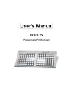
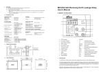
1
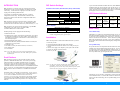
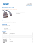
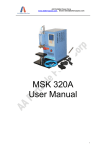
Windows will complete the driver installation in a few seconds. You
only need to run the driver installation once. Windows will load the
USB driver automatically the next time around.
Note that USB driver assigns a virtual serial port for communications.
Control Panel > System > Hardware > Device Manager > Ports (COM
& LPT) will lead you to identify the port number.
User's Manual
Specifications
DIP Switch Settings under
MSE-630A Emulation Mode
Electrical
Power Supply
Run MSE Utility
In addition to Keyed-in Encode, MSE Utility also supports Copy
Encode, File Encode, and Incremental Encode as shown by the main
menu below:
Interface
Current Consumption
100~240VAC/24VDC 2.5A
(hico/loco model)
5VDC 500mA (loco only model)
RS-232 (MSR206) - 9600 baud, none
parity, 8 data bits
RS-232 (MSE-630A) - 9600 baud, odd
parity, 7 data bits
USB to serial conversion
350mA (read), 600mA (write)
Interconnections
Cabling
Pin Assignment (DB9F)
MSE Utility also provides support for non-ISO/ANSI card reading
and writing. What follows is a dialog box for the user to specify the
data format for each track to work with.
MSE-700 Series
Hico/Loco
Tracks 1&2&3
Magstripe Card Encoder
Detachable RJ45M to DB9F
for communications
Detachable RJ45M to USB
for communications
PS/2 power stealer U- cable
(loco only model)
TXD (2), RXD (3), ground (5),
CTS (7), RTS (8)
Mechanical
Casing
Swipe
Dimensions
Weight
ABS
Manual, unidirectional
8.4"Lx2.5"Wx2.5"H
(212mmx63mmx63mm)
1.28lbs (0.58kg)
Environmental
Operating Temperature
Storage Temperature
0oC~40oC, 20%~90%RH, non-condensing
o
o
-20 C~70 C, 20%~90%RH,
non-condensing
Performance
Media Life
Install MSE Utility and USB Driver
There are two subfolders on the utility/driver CD: MSE Utility and
USB Driver. Run MSE700.msi from the MSE Utility folder and
follow the instructions to complete the utility installation.
Windows will prompt you to install a device driver for the newly
detected hardware when you plug in the USB cable to your host PC
the first time. Specify the path to the USB Driver folder and
4
Media Speed
Media Coercivity
Media Thickness
Low Amplitude Reading
Error Rate
MTBF
1,000,000 passes for both read and
write heads
5~50IPS (read), 5~30IPS (write)
300~4000 Oersted (read),
300~4000 Oersted (write)
0.010~0.080"(0.25mm~2.03mm)
30% (210BPI) or 40% (75BPI)
at 10~40IPS
<0.5% (read), <0.75% (write)
95,000 hours
5
Models
Main Spec.
MSE-730
Loco only Encoder
MSE-750
Hico/Loco Encoder
MSE-770
Hico/Loco Industrial Encoder
INTRODUCTION
DIP Switch Settings
MSE-700 Series is a manual swipe type magstripe card encoder
intended for use with a personal computer via the RS-232 or USB
connectivity. It reads and writes magstripe cards with coercivity
ranging from 300 through 4000 Oersted.
Emulation Mode (SW1)/Data Bit (SW2)/Parity (SW3&SW4)
Two models are available from MSE-700 Series - hico/loco
configurable and loco only. All information contained in this
document is pertinent to the hico/loco configurable model unless
otherwise noted.
MSE-700 Series reads and writes data format as specified by ISO
7811/2 through 5 and ANSI 4.16 1983. Any ISO/ANSI standard
track format can be read/written from/to any track location (1, 2, or 3).
MSE-700 Series also supports custom data format - any BPC/BPI
combination on any track, such as T1:5BPC/75BPI,
T2:6BPC/210BPI, and T3:7BPC/75BPI.
Standard package comes equipped with the following:
· MSE-700 main unit
· Switching power supply (100~240VAC input/24VDC 2.5A output)
for Hoco/Loco model, the Loco only model is accessorized with a
detachable power stealer U-cable that draws 5VDC 500mA power
from the keyboard port.
· Detachable RS-232 cable (beige)
· Detachable USB cable (black), bundled in Hico/Loco model, but
optional for Loco only model
· Utility/driver CD
· Two blank test cards (one hico & one loco, or two loco)
· One cleaning card
· User's Manual
Notes: Loco only model is accessorized with a detachable power
stealer U-cable that draws the 5VDC 500mA power from the
keyboard port.
Emulation Mode
SW1
Off
MSR206
On
MSE-630A
Date Bit
SW2
Off
8
On
7
Parity
(when SW2 is on)
SW3
SW4
Off
None
Even
Off
On
On
Mark
Odd
Upon successful installation of MSE-700 Series, under MSR206
emulation mode, only the green LED comes on and stays on. In
contrast, under MSE-630A emulation mode, all three LEDs (green,
yellow, and red) come on simultaneously for about a second then go
off altogether, and the encoder beeps momentarily.
LED Status Indicator
Emu Mode All LEDs Green LED
Off
On
Not
Ready for
MSR206 Applicable
Next
Command
Yellow LED
On
Ready to
Read/Write
Red LED
On
Error
Condition
Ready for
Next
Command
Ready to
Write
Error
Condition
MSE-630A
Factory Defaults
DIP Switch Factory Defaults
SW1 (Off)
SW2 (Off)
SW3/SW4 (Off/Off)
MSR206 Emu
8-Bit Data
None Parity
Notes: Baud rate is set to 9600 by default. Different speed can be
custom-configured at factory upon request.
Installation
Follow the steps below to interconnect MSE-700 Series to your PC:
1. Power off your PC.
2. Connect RJ45M end of RS-232 cable to the encoder.
3. Connect DB9F end of RS-232 cable to a free serial port on your
system.
4. Connect stereo plug of AC adapter to power jack on the encoder.
5. Connect AC adapter to electrical outlet.
6. Power on your PC.
Ready to
Read
MSE Utility
About MSE Utility
MSE Utility is a productivity tool intended primarily for use with
ISO/ANSI-compliant magstripe cards. ISO or ANSI specifies 7 bits
per character as the standard data format for track 1, and 5 bits per
character for both track 2 and track 3. ISO or ANSI also specifies 210
BPI as the encoding density for tracks 1 and 3, and 75 BPI for track 2.
We use ISO, ANSI, or ISO/ANSI interchangeably throughout this
document.
Set Up MSE Utility
Set up the software to be compatible with the hardware in order to
establish successful communications between the two. If your encoder
is configured to operate under the MSR206 emulation mode, i.e., all
four DIP switches are turned off as shown by the left side drawing,
then set up MSE Utility per the right side menu:
Dual Platform
MSE-700 Series supports two most popular magstripe encoder
platforms - MSR206 and MSE-630A. You can run your existing
application under its compatible emulation mode. For instance,
if your have a piece of software which was written to MSR206
command set, then the same software will be able to interoperate
with MSE-700 Series when the hardware is set to MSR206 emulation
mode. Conversely, an existing MSE-630A application will run with
MSE-700 Series when the encoder is set to MSE-630A emulation
mode.
Notes: Use the power stealer instead of the AC adapter for the loco
only model. Connect the PS/2 ends of the U-cable to the
keyboard port on your PC and your keyboard respectively then
connect the stereo plug to the power jack on the encoder.
Emulation mode is configurable via a DIP switch. All four switches
are set to off at factory. The default settings enable MSE-700 Series
to run under the MSR206 emulation mode with its RS-232
parameters set to none parity and 8 data bits. Flip all four switches
on if you prefer to operate MSE-700 Series under the MSE-630A
emulation mode with its RS-232 parameters set to odd parity and 7
data bits.
1
DIP Switch Settings under
MSR206 Emulation Mode
Alternatively, if your encoder is configured to operate under the MSE630A emulation mode, i.e., all four DIP switches are turned on as
shown by the left side drawing, then set up MSE Utility per the right
side menu:
2
3