1
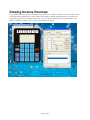
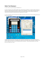
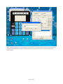
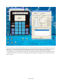
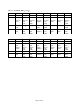
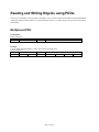
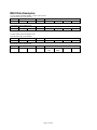
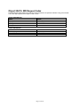
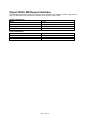
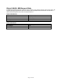
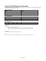
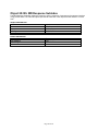
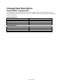
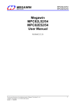
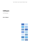
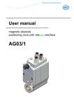
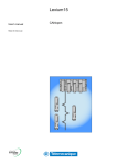
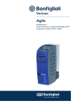
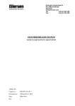
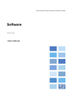
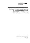
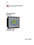
Operator Interface
User Manual
Rev 1.0
Page 1 of 24
Overview:
This document describes how to use the INC, LLC. Operator Interface. Please reference the CANopen software
specifications document for more details.
Page 2 of 24
Table Of Contents:
Overview:............................................................................................................................................................................................2
Table Of Contents:............................................................................................................................................................................3
Operation Overview:.........................................................................................................................................................................4
Drawing Screens Overview:............................................................................................................................................................5
Static Text Example:....................................................................................................................................................................6
BUTTON Example:.....................................................................................................................................................................9
Default PDO Mapping:..............................................................................................................................................................10
Reading and Writing Objects using PDOs..................................................................................................................................11
Multiplexed PDO........................................................................................................................................................................11
MUX Data Objects:....................................................................................................................................................................12
MUX Data Examples:................................................................................................................................................................13
Multiplexed Data Objects:.............................................................................................................................................................14
Object 2A00h: MD Request Control Byte .............................................................................................................................14
Object 2A01h: MD Request Index..........................................................................................................................................15
Object 2A02h: MD Request SubIndex...................................................................................................................................16
Object 2A03h: MD Request Data............................................................................................................................................17
Object 2A10h: MD Response Status Byte.............................................................................................................................18
Object 2A11h: MD Response Index........................................................................................................................................19
Object 2A12h: MD Response SubIndex.................................................................................................................................20
Object 2A13h: MD Response Data.........................................................................................................................................21
Changed Item Description:............................................................................................................................................................22
Object 2080h: Changed Item....................................................................................................................................................22
Object 2081h: Changed Item Data...........................................................................................................................................23
Changed Item Examples:...............................................................................................................................................................24
Example 1:...................................................................................................................................................................................24
Example 2:...................................................................................................................................................................................24
Example 3:...................................................................................................................................................................................24
Page 3 of 24
Operation Overview:
The CANopen Operator Interface is designed to allow the user to receive and send data to the network. For those
familiar with Windows programming, the device operates in a similar manner. When the user presses a button on the
operator interface, the interface sends a PDO on the CANopen network indicating which button was pressed and. This
is similar to windows messaging. To control the display or to send information to the user, the network can send an
SDO or PDO to the corresponding object.
Page 4 of 24
Drawing Screens Overview:
The programmer can draw screens on the display using the INC, LLC. Operator Interface tool. The tool allows objects
to be dragged and dropped on the PC screen and the actual display is updated simultaneously if it is connected. The
component properties can be changed using the tool. It is very similar to designing a form with Visual Basic or C++
Builder.is designed to allow the user to receive and send data to the network.
Page 5 of 24
Static Text Example:
To draw a screen, first open the Operator Interface Tool.
It is best to design the screen with the module online. This allows the programmer to see what it actually looks like, as
the PC has to approximate pixels to display the 128x64 pixels of the display. To work online, Press the Start Network
button then press the Network Browse button. If there are any Operator Interface Nodes found, the program will
indicate the node number detected then open the configuration tool windows.
To work on a particular screen, use the Screen spin button to select the screen to edit. To clear an existing screen, press
the Delete Screen Button.
A simple starting screen can be created using a Static Text Object. Select the Static Text Tab on the Interface Tools
window. Select an existing entry or a blank entry by clicking on the Text String column of the Static Text table. To edit
the text, double click on the text or press the edit button after selecting it. This will bring up the Static Text editor.
Enter a text string such as “hello”
Page 6 of 24
After entering the string press ok. If working online, the data will be sent to the interface and analyzed. If accepted, the
new value will be displayed in the table. To place the static text object onto the screen, drag the text string to the
display window.
Page 7 of 24
The new text string will be displayed on the screen. The current object that is selected has a flashing box around it. The
flashing box is just an indicator to the programmer and will not show up during runtime. The text attributes (position,
font, Mode, etc.) can be changed if necessary. Changing the attributes can be accomplished by adjusting the
corresponding control on the Interface Tools window. The object can also be selected and moved by holding down the
left mouse button while over the object and dragging it around the display. The design process is similar for the other
types of objects.
Page 8 of 24
BUTTON Example:
To add a button to the screen, select the Button tab and then edit a button.
For a simple test application, select “Increment Object Value” for the action. Click the … button on the Signal Object
entry. This will bring up the Input Object Select screen. This assists the programmer in picking the correct object. For
this example, select UNSIGNED8 for the Data Object Type and 1 for the Data Object Instance. This example will
place the value of 0x26000100 in the Signal Object. Enter 1 for the signal value, then press ok. You will see the
information in the Buttons table. Drag and drop the button onto the display. Save the screen by pressing the Save
Screen Button. To refresh the screen, press the refresh screen button. This will refresh the screen to get rid of extra
pixels and allow the user to select the button. Press the “enter button” on the display. This will Increment the value in
the Object at Index 0x2600 SubIndex 01. Read the value by selecting the Module->SDO from menu. Each time the
button is pressed the value is incremented. To see the PDO that is generated, set the Node to operational (if it is not) by
selecting Module-> Node->Set Operational from the menu. Using a CAN viewer, a PDO should be generated with the
object in the first four bytes and the value in the next byte.
PDO:
IndexLSB
0x00
IndexMSB
0x26
SubIndex
0x01
Length
0x00
Page 9 of 24
Value
Val
Don’tCare
XXX
Don’tCare
XXX
Don’tCare
XXX
Default PDO Mapping:
TX PDO
1
2
Byte(1)
TBD
MUX
Data
Response
Status
3
Changed
Item
(LSB)
MPDO
Addr
4
RX PDO
1
2
3
4
Byte(1)
Screen
Command
MUX
Data
Request
Control
TBD
MPDO
Addr
Byte(2)
Byte(3)
Byte(4)
Byte(5)
Byte(6)
Byte(7)
Byte(8)
MUX
Data
Response
Index
(LSB)
Changed
Item
MUX
Data
Response
Index
(MSB)
Changed
Item
MUX
Data
Response
SubIndex
MUX
Data
Response
Data
MUX
Data
Response
Data
Changed
Item Data
Changed
Item Data
MPDO
Index
(LSB)
MPDO
Index
(MSB)
MUX
Data
Response
Data
(LSB)
Changed
Item Data
(LSB)
MPDO
Data
(LSB)
MPDO
Data
MPDO
Data
MUX
Data
Response
Data
(MSB)
Changed
Item Data
(MSB)
MPDO
Data
(MSB)
Byte(2)
Current
Screen
MUX
Data
Request
Index
(LSB)
Byte(3)
Byte(4)
Byte(5)
Byte(6)
Byte(7)
Byte(8)
MUX
Data
Request
Index
(MSB)
MUX
Data
Request
SubIndex
MUX
Data
Request
Data
(LSB)
MUX
Data
Request
Data
MUX
Data
Request
Data
MUX
Data
Request
Data
(MSB)
MPDO
Index
(LSB)
MPDO
Index
(MSB)
MPDO
SubIndex
MPDO
Data
(LSB)
MPDO
Data
MPDO
Data
MPDO
Data
(MSB)
Changed
Item
(MSB)
MPDO
SubIndex
Page 10 of 24
Reading and Writing Objects using PDOs.
There are two methods for writing Objects using PDOs. One is the use of a Destination Address Mode DAM-MPDO
(CANopen standard) and the other is to use the MUX Data Objects. For reading objects, the user must use the MUX
Data method.
Multiplexed PDO
DAM-MPDO:
Request (RxPDO)
Byte 0
Node-ID
Byte 1-2
Index
Byte 3
SubIndex
Byte 4-7
Request Data
Example:
To write Index 0x2800 SubIndex 1 with a value of 0x01 On Node 0x0A
Send the following:
Byte 0
Byte 1-2
Byte 3
Byte 4-7
0x0A
0x00
0x28
01
0x01
0x00
0x00
Page 11 of 24
0x00
MUX Data Objects:
To read and write objects using PDOs, the MUX Data objects were created. The mechanism works with a request
response method. RxPDO 2 is mapped (by default) with the Mux Request values and TxPDO 2 is mapped with the
Mux Data Response values.
The default mapped PDO format is as follows:
Request (RxPDO) Format:
Byte 0
Control
Byte 1-2
Index
Control Byte Format:
Bit 7
Bit 6
Reserved
Reserved
Bit 5
Reserved
Byte 3
SubIndex
Bit 4
Toggle
Byte 4-7
Request Data
Bits 3-0
Command
Bit Definitions:
Commands:
0
Nop – No operation is performed
1
Read Object – Object Specified is read and data can be found in MUX Request Data
2
Write Object – Object Specified is written with data supplied in MUX Request Data
Toggle:
The user must toggle this bit if the device is to perform the requested command again. Optionally the user can switch
commands such as write then read or write then NOP then write again.
Response (TxPDO) Format:
Byte 0
Status
Byte 1-2
Index
Status Byte Format:
Bit 7
Bit 6
Error
Reserved
Bit 5
Reserved
Byte 3
SubIndex
Byte 4-7
Response Data
Bit 4
Toggle
Bits 3-0
Command Echo
Bit Definitions:
Commands:
0
Nop – No operation is performed
1
Read Object – Object Specified is read and data can be found in MUX Request Data
2
Write Object – Object Specified is written with data supplied in MUX Request Data
Toggle Echo:
This is the echo of the toggle in the request control byte.
Error:
This bit is set if there was an error performing the requested command. i.e. object doesn’t exist.
Page 12 of 24
MUX Data Examples:
To write Index 0x2800 SubIndex 1 with a value of 0x01
Send the following to the RxPDO:
Byte 0
Byte 1-2
Byte 3
0x02
0x00
0x28
01
0x01
0x00
The TxPDO will be updated with
Byte 0
Byte 1-2
0x02
0x00
0x28
Byte 3
01
0x01
0x00
To Read Index 0x2601 SubIndex 0x01
Send the following to the RxPDO:
Byte 0
Byte 1-2
0x01
0x01
0x26
Byte 3
01
0x00
0x00
The TxPDO will be updated with
Byte 0
Byte 1-2
0x01
0x01
0x26
Byte 3
01
Value
LSB
Byte 4-7
0x00
0x00
0x00
0x00
0x00
0x00
Byte 4-7
Value
0x00
MSB
0x00
Byte 4-7
Byte 4-7
Page 13 of 24
Multiplexed Data Objects:
Object 2A00h: MD Request Control Byte
The MD Request Control Byte Object allows the network to send requests to the operator interface using
process data.
OBJECT DESCRIPTION
INDEX
Name
Object Code
Data Type
Category
2A00h
MD Request Control Byte
VAR
UNSIGNED8
Optional
ENTRY DESCRIPTION
Access
PDO Mapping
Value Range
Default Value
Control Byte Format:
Bit 7
Bit 6
Reserved
Reserved
Rw
Yes
UNSIGNED8
0
Bit 5
Reserved
Bit 4
Toggle
Bits 3-0
Command
Bit Definitions:
Commands:
0
Nop – No operation is performed
1
Read Object – Object Specified is read and data can be found in MUX Request Data
2
Write Object – Object Specified is written with data supplied in MUX Request Data
Toggle:
The user must toggle this bit if the device is to perform the requested command again. Optionally the user can switch
commands such as write then read or write then NOP then write again.
Page 14 of 24
Object 2A01h: MD Request Index
The MD Request Index allows the network to send requests to the operator interface using process data.
The index object specifies the object to read or write.
OBJECT DESCRIPTION
INDEX
Name
Object Code
Data Type
Category
2A01h
MD Request Index
VAR
UNSIGNED16
Optional
ENTRY DESCRIPTION
Access
PDO Mapping
Value Range
Default Value
Rw
Yes
UNSIGNED16
0
Page 15 of 24
Object 2A02h: MD Request SubIndex
The MD Request SubIndex allows the network to send requests to the operator interface using process
data. The SubIndex object specifies the subindex of the object to read or write.
OBJECT DESCRIPTION
INDEX
Name
Object Code
Data Type
Category
2A02h
MD Request SubIndex
VAR
UNSIGNED8
Optional
ENTRY DESCRIPTION
Access
PDO Mapping
Value Range
Default Value
Rw
Yes
UNSIGNED8
0
Page 16 of 24
Object 2A03h: MD Request Data
The MD Request Data allows the network to send requests to the operator interface using process data. The
Request Data object specifies the data to be written to the requested index and subindex. The amount of
data transferred depends on the size of the object written to.
OBJECT DESCRIPTION
INDEX
Name
Object Code
Data Type
Category
2A03h
MD Request Data
VAR
UNSIGNED32
Optional
ENTRY DESCRIPTION
Access
PDO Mapping
Value Range
Default Value
Rw
Yes
UNSIGNED32
0
Page 17 of 24
Object 2A10h: MD Response Status Byte
The MD Response Status Byte Object allows the network to get the response to the request made using the
MD Request Objects using process data.
OBJECT DESCRIPTION
INDEX
Name
Object Code
Data Type
Category
2A10h
MD Response Status Byte
VAR
UNSIGNED8
Optional
ENTRY DESCRIPTION
Access
PDO Mapping
Value Range
Default Value
Status Byte Format:
Bit 7
Bit 6
Error
Reserved
Ro
Yes
UNSIGNED8
0
Bit 5
Reserved
Bit 4
Toggle
Bits 3-0
Command Echo
Bit Definitions:
Commands:
0
Nop – No operation is performed
1
Read Object – Object Specified is read and data can be found in MUX Request Data
2
Write Object – Object Specified is written with data supplied in MUX Request Data
Toggle Echo:
This is the echo of the toggle in the request control byte.
Error:
This bit is set if there was an error performing the requested command. i.e. object doesn’t exist.
Page 18 of 24
Object 2A11h: MD Response Index
The MD Response Index Object allows the network to send requests to the operator interface using process
data. The index object specifies the object that was written or read from using the MD Request.
OBJECT DESCRIPTION
INDEX
Name
Object Code
Data Type
Category
2A11h
MD Response Index
VAR
UNSIGNED16
Optional
ENTRY DESCRIPTION
Access
PDO Mapping
Value Range
Default Value
Ro
Yes
UNSIGNED16
0
Page 19 of 24
Object 2A12h: MD Response SubIndex
The MD Response SubIndex allows the network to get the response of requests to the operator interface
using process data. The SubIndex object specifies the subindex of the object that was written to or read
from.
OBJECT DESCRIPTION
INDEX
Name
Object Code
Data Type
Category
2A12h
MD Response SubIndex
VAR
UNSIGNED8
Optional
ENTRY DESCRIPTION
Access
PDO Mapping
Value Range
Default Value
Ro
Yes
UNSIGNED8
0
Page 20 of 24
Object 2A13h: MD Response Data
The MD Response Data allows the network to get data returned from requests to the operator interface
using process data. The Response Data object will return the data of the object that was read to the
requested index and subindex. The amount of data transferred depends on the size of the object read from.
OBJECT DESCRIPTION
INDEX
Name
Object Code
Data Type
Category
2A13h
MD Response Data
VAR
UNSIGNED32
Optional
ENTRY DESCRIPTION
Access
PDO Mapping
Value Range
Default Value
Ro
Yes
UNSIGNED32
0
Page 21 of 24
Changed Item Description:
Object 2080h: Changed Item
The Changed Item Object allows the network to detect changes that the operator has made using the
keypad. Example: If the user changes the number in an Operator Input, the corresponding Object Number is
placed into this object.
OBJECT DESCRIPTION
INDEX
Name
Object Code
Data Type
Category
2080h
Changed Item
VAR
UNSIGNED32
Optional
ENTRY DESCRIPTION
Access
PDO Mapping
Value Range
Default Value
RO
Yes
UNSIGNED32
0
Page 22 of 24
Object 2081h: Changed Item Data
The Changed Item Data Object allows the network to detect changes that the operator has made using the
keypad. Example: If the user changes the number in an Operator Input or presses a screen button, the
corresponding Object Data is placed into this object.
OBJECT DESCRIPTION
INDEX
Name
Object Code
Data Type
Category
2081h
Changed Item Data
VAR
UNSIGNED32
Optional
ENTRY DESCRIPTION
Access
PDO Mapping
Value Range
Default Value
RO
Yes
UNSIGNED32
0
Page 23 of 24
Changed Item Examples:
Example 1:
Configuration:
Operator Input 1 is mapped to the first UNSIGNED8 Data In Object. (Index 0x2600 SubIndex 0x01)
Events:
The user changes the value to 57 and presses enter
The Changed Item will indicate 0x26000108
The Changed Item Data will indicate 0x00000039 (57 decimal)
If the objects are mapped into a PDO (by default), the PDO will be sent with the following value:
0x08 0x01 0x00 0x26 0x39 0x00 0x00 0x00
Example 2:
Configuration:
Operator Input 2 is mapped to the third UNSIGNED16 Data In Object. (Index 0x2601 SubIndex 0x03)
Events:
The user changes the value to 1000 and presses enter
The Changed Item will indicate 0x26010310
The Changed Item Data will indicate 0x000003E8 (1000 decimal)
If the objects are mapped into a PDO (by default), the PDO will be sent with the following value:
0x10 0x03 0x01 0x26 0xE8 0x03 0x00 0x00
Example 3:
Configuration:
Operator Input 3 is mapped to the fourth UNSIGNED32 Data In Object. (Index 0x2602 SubIndex 0x04)
Events:
The user changes the value to 200000 and presses enter
The Changed Item will indicate 0x26020420
The Changed Item Data will indicate 0x00030D40 (200000 decimal)
If the objects are mapped into a PDO (by default), the PDO will be sent with the following value:
0x10 0x04 0x02 0x26 0x40 0x0D 0x03 0x00
Page 24 of 24