1
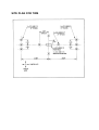
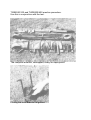
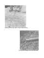
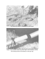
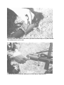
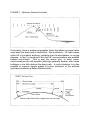
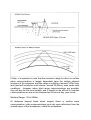
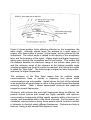
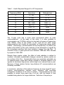
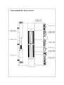
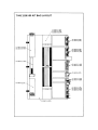
WIDE BAND LIGHTWEIGHT DIPOLES
TWB 2530/100 (100W)
TWB 2530/400 (400W)
TWB 2530/1k (1kW)
USER MANUAL
TWB-11
WIDE BAND TACTICAL DIPOLE ANTENNA SYSTEMS
TWB 2530/100 (100W)
TWB 2530/400 (400W)
TWB 2530/1k ) (1kW)
TWB - 11 USER MANUAL
BRIEF DESCRIPTION
The TWB2530 is a lightweight transportable 3 element horizontal bi-conical loaded
dipole antenna system, supplied complete with its own 11m support mast. The
complete system is stowed in a PVC nylon kit bag for transportation.
PARTS IDENTIFICATION
PART NO
QTY
QTY
QTY
TWB2530 TWB2530 TWB2530
/100
/400
/1kW
TWB -1
2
2
2
TWB -2
6
6
6
TWB -3
6
-
6
TWB -3A
-
6
-
TWB -4
6
6
6
TWB -5
6
6
6
TWB -6
-
-
1
TWB -7
1
1
1
TWB -8
1
1
1
DESCRIPTION
Upper elements 17.22m
long, c/w termination and
strain relief, stored on black
polypropylene storage
boards.
Lower elements c/w
termination adjustable end
ropes and insulators.
Element load assembly 400
watt.
Element load assembly 100
watt.
Carbine hooks. Fitted to
TWB-2 (lower elements).
Lower element guy stakes
15" x 1" x 1" tee section.
Balun transformer 1kW fitted
'N' connector.
Top spreader assembly, c/w
strops.
RG213 cable assembly, c/w
strain relief and 'N' 50 ohm
connectors.
TWB -9
-
1
-
TWB -10
1
-
-
TWB -11
TWB -12
1
1
1
1
1
1
TWB -13
6
6
6
TWB -14
1
1
1
Balun transformer 400W
fitted 'N' connector.
Balun transformer 100W
fitted 'N' connector.
User manual.
Roll up kit bag.
2m long spigoted mast
sections glass fibre.
Mast base, cast aluminium.
TWB -15
2
2
2
Base anchor pins 12" x 3/8".
4
Top stay assembly, all fitted
to 4 way guy ring, c/w
adjusting hanks. (Coded
Red)
Middle stay assembly, all
fitted to 4 way guy ring, c/w
adjusting hanks. (Coded
Blue)
TWB -16
4
4
TWB -17
4
4
4
TWB -18
4
4
4
TWB -19
4
4
4
TWB -20
4
4
4
TWB -21
1
1
1
Bottom stay assembly, all
fitted to 4 way guy ring, c/w
adjusting hanks. (Natural)
27" long 1 1/2" x 1 1/2" tee
section mast ground stakes.
Carbine hooks fitted to TWB19 (guy stakes).
Sledge hammer.
SITE PLAN FOR TWB
Care should be taken to familiarise yourself with all the components
before attempting to erect the antenna system.
NOTE: Be careful that the power rating of the antenna system you are
using is equivalent to, or greater than the transmitter output. If the power
output of the transmitter is greater than the antenna rating, damage can
result to both units.
SITE SELECTION
The TWB series antenna system requires a clear site of 12-15m wide by
52-57m long. The stays are overlength, in order that uneven ground can
be accommodated.
COMMENCING INSTALLATION
(This should be read in conjunction with the series of photographs)
Select the mast base and 2 anchor pins (TWB-14 and TWB-15) and pin
the mast base to the ground with the securing holes along the major
axis. Mark out the mast anchor points as per the plan 3 mast sections
(TWB-13) joined together will give the correct radius. Knock in the 4 guy
stakes (TWB-19), with the carbine hooks pointing toward the mast base,
using the hammer supplied (TWB-21).
Mast assembly can now begin; by first laying the 6 mast sections along
the major axis, with the smaller diameter spigot towards the top, do not
join together at this stage.
The 3 sets of stays can now be fitted to the mast, by fitting the guy ring
over a spigot, to come to rest on the spigot shoulder. The mast stays are
fitted to every second section as follows:
TWB-16
TWB-17
TWB-18
(Top stay, coded Red)
(Mid stay, coded Blue)
(Bottom stay, Natural)
36' level
24' level
12' level
The mast sections can now be joined together. Unreel the mast stays
towards the bottom of the mast, being careful not to tangle them. Pull 3
stays (one from each level) toward a stake on the minor axis and make
off in the carbine hook, tensioning lightly with the plastic adjuster.
Repeat for the 3 stays on the other minor axis being careful to ensure
that these are 180 degrees away on the guy band from the first set you
have fixed. These stays can also be lightly tensioned.
The back stays can now be loosely fixed to the stake under the line of
the mast, the 3 remaining stays should be pulled out in readiness for
erection.
Fit the antenna spreader (TWB-7) to the top mast section spigot and
locate with the balun transformer (TWB-10 100W or TWB-9 400W or
TWB-6 1kW). Fit coaxial cable to strain relief hook on transformer and
connect 'N' connector, first removing the protective dust cap.
The coaxial cable should be passed under the strop attached to the
spreader, to ensure it does not become entangled when the mast is
upright. Unreel the cable along the line of the mast to the mast base.
Fit the two upper elements (TWB-1) to the strops on the spreader.
NOTE: By laying the elements on the ground whilst on the spools, you
will be able to see that one is centre, with two outer spools. These
should be connected to the spreader strops in this orientation.
Fit both sides of the elements to the spreader and connect the fork
terminals to the balun transformer lugs. Unreel the elements to their full
lengths, 3 to one major axis point, 3 to the other. Remove the storage
boards and stow in kit bag.
The antenna system is now ready to be pulled to the vertical.
PULLING TO THE VERTICAL
(Please refer to the series of photographs)
Place the foot of the mast in the mast base cup - One man positions
himself at the head of the mast, the other gathers up the 3 forward stays
which are not attached to a stake, pulls all three to an even tension and
prepares to pull back hard. IMPORTANT: Do not attempt to pull on the
antenna elements, as serious damage could occur. At the mast head
the other person lifts the mast head over his own head and begins to
walk down the mast, raising it over his head as he goes. The man on the
stays pulls back until the mast is vertical, all the remaining stays can now
be fixed to their stake, and all stays are tensioned, leaving the mast
straight and rigidly held.
SAFETY NOTE: Whilst raising the mast, great care should be taken not
to fall over any of the stakes, and that no wires become entangled.
The antenna is now ready to be fully assembled, by fitting the 6 loads
(TWB-3 400W/1kW and TWB-3A 100W) to the upper elements by
means of the carbine hooks and connecting the fork terminals to the
loads.
The 6 lower element assemblies (TWB-2) are now fitted to the loads via
the carbine hook and connecting terminals.
The 6 stakes (TWB-5) are now driven in, 1.2m apart at the extension of
the major axis. These points can be measured by use of the actual
element. Connect lower elements to stakes using carbine hooks and
tension.
The whole antenna assembly is now ready to be connected to your
transceiver.
NOTE: Ensure that the antenna is as straight as possible. The top
spreader assembly is free to rotate on the mast. The complete antenna
can be rotated, by uplifting the 6 tee anchors (TWB-5) and re-locating.
The technical specification of the antenna is enclosed and should be
referred to for signal distribution (Polar diagram).
HINTS ON USE
HF antennas are susceptible to degradation in performance by a number
of factors, mainly due to location i.e. close proximity of foliage, large
vehicles, or escarpments, buildings, etc. Poor soil conductivity, humidity
and a range of naturally occurring phenomena.
Erecting the system very close to trees, or escarpments and buildings
should be avoided where possible.
The antenna is designed for use from 2.5-30MHz, but in some locations
a slightly higher than average VSWR will occur between 14 and
14.2MHz. This is due to ground proximity and that fact that the antenna
is very close to the ground in terms of wavelength at HF frequencies.
FIELD REPAIRS
It is strongly recommended that damaged or inoperative parts are
replaced with new items, however, some field repairs can be carried out
in emergencies.
1.
The elements can be joined by stripping back the outer coating of
PVC and tying with a reef knot.
2.
Non-conducting ropes and straps can be tied using reef, or other
suitable knots.
3.
The mast can be used at varying heights, should a mast section be
damaged or broken.
4.
Other natural objects such as tree stumps, rocks, etc, can be used
to support the system, should anchors be lost or damaged.
RE-STOWING AFTER USE
Operators should learn by heart the location of each component in the kit
bag and all components should remain in the same relative location.
This will help speed assembly and 'on air time' and save frustrating
searches for 'lost' components.
All components should be clean and free of moisture before stowing.
This will aid the longevity of each system.
When not in use, all components should be stored in the kit bag (TWB12).
Before going into the field, operators should train by assembling,
erecting, using and then de-rigging and stowing the TWB2530 so that a
routine can be worked out between 2 or 3 people. This will help rapid
deployment and deployment under hostile conditions and keeps wasted
time to a minimum.
Some users may wish to vary the routine laid down here, to suite their
own organisation. A target time of 15 minutes should be set for the
assembly and deployment of the TWB2530.
In practice we have found that 25-30 minutes for 2 people is average.
TWB2530/100 and TWB2530/400 erection procedure.
Use this in conjunction with the text.
The complete antenna, unwrapped, ready for deployment.
Pinning the mast base to the ground.
Marking out the guy radius, using 3 mast sections.
The foot of the mast in the cup of the base.
Guy assembly ready for fitment of the mast spigot.
Guy ring on the spigot shoulder, with the reset mast section ready to
locate. Note that the knots are pulled clear of the shoulder, so that
the locating section sits squarely on the guy ring.
Top crossarm and balun transformer
Assembly on mast head.
Ensure that coaxial cable is passed under the crossarm catenary.
Ensure that the coaxial connector protective dust cap is in place when
the antenna is not in use.
Connecting the antenna elements to the balun transformer.
The crossarm rigged with coaxial cable and
antenna element.
Coaxial cable strain relief fitting on balun transformer.
Pushing up the mast.
Guy stake with all stays attached and adjusted.
Connecting loads to upper and lower elements.
Comparison between CC-104017-3A (100W) & CC-104017-3 (400W)
load resistors. The 400W unit is larger.
WHAT IS THE BEST FREQUENCY?
Selecting the best HF frequency for communicating with another station is
often a difficult task for radio operators, because of the ever-changing
factors that determine the paths of radio waves. However, with some
practice and some familiarity with these factors, proficient radio operators
can select an operating frequency that will provide the best chance for
communications at a given time.
Although there are too many variables to allow completely accurate
forecasting of optimum frequencies over any distance at any time, the
following descriptions are intended to provide enough information to give
the radio operator a feeling for the factors that must be considered when
selecting a frequency for communications over a known distance. This
information assumes that the transceiver, antenna and counterpoise or
ground are properly set up and connected, and that the antenna is located
in the clear; as far as possible from surrounding buildings, trees and other
obstacles.
Short Range: 1 to 30km
HF radio wave propagation over short range depends primarily upon the
direct, line-of-sight path between the antennas of the communicating
stations. Obstacles such as buildings and trees will weaken signals on the
direct path, and hills or mountains may block the signals entirely.
Therefore it is important to set up the antennas within, or as near as
possible to, the line-of-sight path between them. For best coverage in all
directions, this calls for the highest practical location, but for optimum
signal in one direction only when a hill or mountain is available, the
antenna is better set up slightly below the peak on the favouring side, as
shown in Figure 1. Generally, any frequency propagates well over line-ofsight, but often the best frequency is one on which noise and interference
from undesired signals are minimal, usually between 20 and 30MHz.
Antennas at both stations should be vertical.
FIGURE 1 - Optimum Antenna Location
Fortunately, there is another propagation factor that allows communication
even when the direct path is obstructed: this is reflection. HF radio waves
reflect off of just about anything, including even the atmosphere, to varying
degrees. In fact it is because of this that HF communications are possible
beyond line-of-sight. This is also the reason why, in many cases,
communications are still possible (although generally weaker) even when
buildings or low hills obstruct the direct path. In such situations it is often
possible to improve signals greatly by minor relocation of the antenna
(perhaps introducing a better reflection path).
At the longer limits of short-range communications (20-100km), the
transmitted signal is weakened by dispersion and absorption by the
atmosphere, and the curvature of the surface of the Earth begins to
obscure line-of-sight. At this range the choice of frequency becomes more
critical. Communications are generally possible even beyond line-of-sight,
because of slight bending (refraction) of the radio waves by the
atmosphere close to the ground (Figure 2). Low frequency HF signals
carry along the ground more readily than those at higher frequencies, but
the lower frequency signals are also absorbed more readily. However, the
effects of the atmosphere on radio signals vary greatly between day and
night, and with changes in season and temperature. Therefore the best
frequency for communications will also vary between day and night, and
from season to season.
During daylight hours on a non-line-of-sight path between 20 and 100km,
frequencies above about 8 or 9MHz will usually not be useful. The best
frequency is likely to be found between 2 and 8MHz, with the best choice
with a vertical antenna for distances out to about 50km likely to be the
quietest frequency around 6 to 8MHz. During hours of darkness, as there
is much less absorption, signals may be stronger on lower frequencies,
although noise will be a problem at the lower frequencies in the summer.
One other factor that becomes important at these ranges is the
conductivity of the ground itself. Salt water, being highly conductive, will
often allow direct communications over more than 100km; while rock or
sandy soil may limit communications to 20km or less. In all cases,
communications will generally be better if a ground rod is installed and
connected to the grounding terminal on the antenna tuner or transceiver,
along with the counterpoise wire, instead of when using the counterpoise
wire alone. See Figure 3.
Finally, it is important to note that the maximum range for direct or surface
wave communications is largely dependent upon the relative physical
locations of the antennas, and this range is unlikely to exceed 100km over
land (and will usually be much shorter, around 20-50km), even under ideal
conditions. However, when short range communications are possible,
they will also be the most reliable, and it should not be difficult to maintain
communications on one or two frequencies 24 hours a day, year round.
Medium Range: 30 to 500km
At distances beyond those which support direct or surface wave
communication, radio communications must rely upon reflections from the
ionised layers of the atmosphere, called the ionosphere.
Radio waves reflected from the ionosphere are called skywaves, and can
provide stronger signals than surface waves at distances greater than
several kilometres, because skywaves are not subject so much to the
heavy absorption that occurs to surface waves.
There are actually several layers of the ionosphere that can reflect radio
waves between about 100 and 420km above the surface of the Earth. The
existence of these layers, and their actual altitude and density at any given
time, is determined by the sun's energy, which varies according to latitude
and the time of day, season of year, and also over an 11-year cycle. The
ionospheric layers are most dense just after noon, and least dense just
after midnight. The ability of the ionosphere to reflect radio waves is
determined by the altitude and density of the layers, and also the
frequency in use.
Some portion of the radio signals leaving the transmitting antenna rise
through the lower atmosphere until they reach these layers, and if
conditions are just right, the signals are then reflected back down to the
receiver. Under ideal conditions and at the ideal frequency, such skywave
signals can provide loud and clear communications over very long
distances. Unfortunately, it is impossible to always predetermine what the
ideal conditions and frequency are, but by understanding some of the
principles involved, the operator can still often determine the most likely
time and frequency for making contact.
As shown in Figure 4, the propagation distance of skywaves is determined
by the altitude at which they are reflected back down toward the ground: if
the reflecting layer is high the distance will be longer than if the reflecting
layer is low. During hours of daylight, the reflective layers are at lower
altitude than at night, and thus are most useful for medium range
communications. After dark these same signals will reflect at higher
altitude, and thus have longer range.
Figure 5 shows another factor affecting reflection by the ionosphere; the
wave angle. Although signals leave the antenna at a wide range of
angles, only those below a certain "critical angle" will be reflected by the
ionosphere. The critical angle is related to the density of the ionospheric
layer and the frequency of the signal. Higher angle (and higher frequency)
waves pass through the ionosphere and off into space. This means that
the distance between the maximum range of the surface wave (point A)
and the minimum range of the skywave at the highest possible angle
(shortest possible hop, point B) cannot be reached, and hence this region
is called the "Skip Zone". The critical angle is higher for lower frequencies,
and lower for higher frequencies.
The existence of the Skip Zone means that for medium range
communications there is usually a frequency limit above which
communications are not possible: signals above the limit will be reflected
at an angle that will cause them to return to the ground beyond the desired
receiving station. Table 1 shows approximate minimum and maximum
ranges for several frequencies.
Obviously, with optimum day and night frequencies being so different, the
periods around sunrise and sunset are highly unstable, with optimum
communication frequencies shifting rapidly upwards within a few hours of
sunrise, and downwards within a few hours of sunset. For this reason, any
scheduled communications during these periods should include a number
of channels to check at widely different frequencies. Contacts are likely to
fade out, forcing a shift several MHz higher or lower.
For medium range communications at night, use the lowest available
frequency that is not masked with noise. This last condition, noise, will be
higher in the summertime (forcing higher frequency operation) because of
electrical storms, than during the winter. Also, the increased amount of
sunlight during the summertime increases the density of the ionospheric
layers, which results in greater absorption of the lower frequencies, and
better refraction of the higher. This also calls for using generally higher
frequencies during the summer. Of course, seasonal effects are greater
farther from the equator.
The reliability of medium range communications is not as good as for short
range, and it may be difficult, if not impossible, to maintain communications
at all hours of day and night. To do so would certainly require at least
several changes of frequency as ionospheric conditions change. In
practice, there are often times (particularly during daylight) when the
lowest frequency that could provide the necessary hop distance will be
totally absorbed, in which case contact will not be possible (until later in the
day). Solar conditions, discussed below, also affect medium range
communications, particularly at higher frequencies.
Long Range: 500+km
At long range the effects of ionospheric variations mentioned above are
greater, and reliable prediction of optimum communications frequencies is
more difficult. Even so, it is worthwhile to bear in mind that worldwide
communications are possible even with 10 watts of power when conditions
are just right. As with medium range communications, long range involves
use of higher frequencies during the day, and lower frequencies at night.
As can be seen from Table 1, the optimum frequency for long range is
higher than that for medium range when time and all other factors are
equal. Note however, that frequencies above about 15MHz are usually
useless for medium or long-range communications after dark.
Because of greater dependence of long-range communications on the
ionosphere, it is useful for the operator to maintain constant awareness of
long range propagation conditions. This can be done by regularly listening
to the international broadcasting bands and noting trends in band activity
and signal strengths. Noting the time a station is heard and the location of
the broadcasting transmitter can help in planning two-way communications
on nearby frequencies, although one should bear in mind that
broadcasters use thousands or millions of watts, and so their signals will
propagate acceptably where normal transceivers may not.
By listening it can usually be shown that as one tunes higher in frequency
signals from a particular region will become stronger until they suddenly
disappear. The strengthening of signals is caused by the lessening of
absorption as frequency is increased, and the drop off of signals results
when the signals are no longer refracted sufficiently to return to the ground
at the receiver. One can gather from this that the best frequency for
communication is just below that at which signals are no longer heard (as
one tunes upward).
The reliability of long range communications depends, in addition to all of
the factors mentioned previously for short and medium ranges, upon solar
conditions as they effect the geomagnetic field of the Earth (since this, in
turn, determines the condition of the ionosphere). This subject is very
complex, so only a few of the more useful factors will be mentioned here.
The reliability and stability of radiation reaching the Earth from the Sun
goes through two overlapping cyclic repetitions: one every 27 days, and
one approximately every 11 years. The nature of the 27-day cycle simply
results in radio propagation conditions on one day being generally similar
to conditions 27 days before, and 27 days after, that day. This is because
the Sun takes approximately 27 days to make one full rotation. The
importance of this cycle is that poor conditions caused by flares and other
disturbances on the surface of the Sun will tend to repeat every 27 days.
Table 1 - Useful Skywave Ranges For HF Frequencies
Frequency (MHz)
Noon (km)
Midnight (km)
2
0 - 120
0 - >>
4
0 - 400
0 - >>
8
0 - 800
500 - >>
10
300 - 1600
1000 - >>
15
800 - >>
1600 - >>
20
1200 - >>
None
25
1600 - >>
None
30
2000 - >>
None
The 11-year cycle has a much more pronounced effect on radio
communications: at the peak of the cycle it is often possible to
communicate over 10,000km with just a few watts of power on frequencies
near 30MHz, while at the bottom of the cycle all but short range
communications will usually be impossible on frequencies above about
22MHz. Interestingly, communications at low frequencies (2 to 6MHz) are
better at the bottom of the cycle, because of less absorption of signals by
the ionosphere resulting from less excitation energy from the Sun. A
minimum of this 11-year cycle will occur between 1986 and 1988, followed
by a peak in 1990-1991.
Despite these regular cycles, the effect of solar radiation is subject to
constant, ultimately unpredictable changes caused by random events on
the surface of the Sun. Occasionally these are especially noticeable, as
for example when a solar flare causes a partial or complete fadeout of all
signals on shortwave frequencies, which might occur several times a year.
Because of these random factors, long distance HF communications are
ultimately unreliable.
In conclusion, selection of the optimum frequency for long range HF pointto-point communications requires some familiarity with prevailing
ionospheric conditions at the time of interest. Communications are only
possible at certain times each day (if at all), with the length of time
available being shorter for longer distances. Selection of frequency is
critical, as the useful range of frequencies becomes narrower at longer
distances, and if a schedule is set up there should be several alternate
frequencies to try (beginning at the highest expected frequency, an
working lower), to take advantage of the lower absorption at higher
frequencies, and to allow for random changes in ionospheric conditions. If
contact cannot be made on the established frequencies, try again an hour
later, and starting an hour earlier on the following day.