1
Release 5.3
October 2007
User´s Manual
User Documentation
Version
:
V 5.3
Date
:
October 2007
ACCESS e.V.
Intzestr. 5, 52072 Aachen
'Resolution of partial differential equations is more about art than science'.
Apocryphal quotation from Numerical Recipes in Fortran.
'2 + 2 = 4 except for large values of 2'.
Anonymous.
'42'.
Douglas Adams.
Table of contents
Table of contents
1
INTRODUCTION.
1.1 Scope of the software MICRESS®.
1.2 Contact in case of problems.
6
6
7
2
WHAT'S NEW IN VERSION 5.3?
2.1 Speed enhancement
2.2 Averaging
2.3 Curvature undercooling and nucleation
2.4 Stoichiometric phases
2.5 ‘Grain data’ output
2.6 Compressed results
2.7 Messages
2.8 CygWin
8
8
8
8
8
8
9
9
9
3
INSTALLATION.
3.1 System requirements.
3.2 Other platforms.
3.3 MICRESS distribution files.
3.4 Installation Procedure.
3.5 MICRESS® license.
3.6 Thermo-Calc™ license.
10
10
10
11
12
12
12
4
RUNNING MICRESS®.
4.1 Preparing the input data (pre-processing).
4.2 Start the calculation.
4.3 Check the output.
13
13
14
14
5
DRIVING FILES.
5.1 ‘Switching’ to keyboard input.
5.2 MICRESS License.
5.3 Language settings.
5.4 Dimension parameters.
5.5 Restart.
5.6 Output name.
5.7 Outputs.
5.8 Time input data.
5.9 Phase data.
5.10 Grain input data.
5.11 Nucleation parameters.
5.12 Phase interaction data.
5.13 Diffusion data.
5.14 Phase diagram data.
5.15 Initial concentrations.
5.16 Elastic material data
5.17 Temperature data.
5.18 Latent heat parameters.
5.19 Boundary conditions.
15
15
15
16
16
17
18
19
22
23
23
27
29
31
32
35
35
36
37
37
6
KNOWN ISSUES.
6.1 Problems with some Linux distributions.
6.2 Restarting simulations.
6.3 μ(T) and stability criteria.
6.4 Nucleation of liquid.
6.5 Image drivers for Display MICRESS.
41
41
41
41
41
41
MICRESS user’s manual
4 / 98
Table of contents
7
POST-PROCESSING.
7.1 Available post processing tools.
7.2 Display MICRESS.
7.3 Libraries used by MICRESS and Display_MICRESS.
42
42
42
56
8
INSTALLING MICRESS®.
8.1 Installing MICRESS® under Windows™.
8.2 Installing MICRESS® under UNIX.
8.3 Starting a FLEXlm™ license server under Windows™.
60
60
64
65
9
STANDARD EXAMPLES.
9.1 Aluminium copper.
9.2 Delta-gamma.
9.3 Gamma-alpha.
9.4 Grain growth.
9.5 ‘Phosphorus peak’.
9.6 Recrystallisation.
9.7 Strees.
9.8 Basic TQ-coupling.
9.9 Temperature.
66
66
66
66
66
68
70
71
71
71
10 FULLY ANSWERED QUESTIONS.
10.1 Reading MICRESS results.
10.2 Decrypting the nucleation message.
10.3 Reading-in initial microstructures.
72
72
75
75
11 APPENDIX.
11.1 Glossary.
11.2 Reference list.
11.3 MICRESS license
11.4 Driving file.
78
78
79
81
87
MICRESS user’s manual
5 / 98
Introduction
1
Introduction.
1.1 Scope of the software MICRESS®.
The present software MICRESS® (MICRostructure Evolution Simulation Software) is developed for a
time- and space-resolved simulation of solid-liquid and solid-solid phase transformations in metallic
alloys by solving the free boundary problem of moving phase boundaries.
MICRESS is based on the multi-phase-field method which defines a phase-field parameter for each
phase involved. The phase field parameter describes the fraction of each phase as a continuous
function of space and time. Additionally each single grain is mapped to a distinct phase-field
parameter, and formally treated as an individual phase. The theory leads then to a set of coupled
partial differential equations which describes the evolution of the phase-field parameter, and
concentration, temperature, stress and flow fields. (Please see Reference list in section 11.2 for some
literature on that subject).
The total set of equations is solved explicitly by the finite difference method on a cubic grid.
MICRESS handles:
•
1, 2, 3 dimensional calculation domains
•
arbitrary number of components, phases and grains
•
solid-solid and solid-liquid interaction
•
anisotropy of grain boundaries, mobility and energy
•
it also supports run-time coupling to thermodynamic database (via the TQ-interface of
Thermo-Calc™)
Restrictions:
•
square (cubic), equally spaced grid.
MICRESS user’s manual
6 / 98
Introduction
1.2 Contact in case of problems.
The MICRESS® site can be visited at:
www.micress.de
It has lots of up-to-date information, and provides links to the MICRESS user forum and the MICRESS
hotline web page (for which you should have been issued a user-ID and password).
Looking up the MICRESS forum should be the first step if you were to experience any difficulty, as it is
most likely to have the answer to your question (chances are someone already asked the same!), if
not, do not hesitate to post a message: it will be answered as soon as possible.
As was creatively phrased by someone who wishes to remain anonymous, “the forum is the
main operating theatre of our Reliable Task-Force for MICRESS® which thrives to provide
Responses Tailored For MICRESS®”.
MICRESS user’s manual
7 / 98
What's new?
2
What's new in version 5.3?
2.1 Speed enhancement
Some very noticeable improvement in speed could be achieved; the memory usage in 2D was
significantly decreased.
2.2 Averaging
The algorithm for the averaging along the normal to the interface has been improved. The possibility of
averaging not only along the normal itself, but also with some deviation, has been added, which helps
minimising the effects of the grid anisotropy.
2.3 Curvature undercooling and nucleation
The curvature undercooling can now be taken into account when evaluating nucleation undercooling
at interfaces.
2.4 Stoichiometric phases
Using stoichiometric phases has become significantly less error-prone and raises fewer numerical
issues.
2.5 ‘Grain data’ output
A new output is available, specifying for each grain and output time, the grain’s number, phase
number, its surface (volume in 3D), its derivative over time, the grain perimeter (surface in 3D), as well
as its number of neighbours, and the list of its neighbours.
This data can readily be used to evaluate grain size distribution, or other user-defined plots.
MICRESS user’s manual
8 / 98
What's new?
2.6 Compressed results
MICRESS can now write compressed results: the gains depend on the type of output and the
simulation, but fields which have a constant value over the bulk of a grain ('phas', 'intf', ...) get
compressed down to a few percent of their original size, for the others outputs, apart from a few
oddities, a gain of at least one third can be expected. The results of the 'distribution examples' were
reduced down to a quarter of their original size.
2.7 Messages
The 'messages' are now 'embedded' in the executable, making sure the set corresponding to the
current executable is used, and freeing the user of this external dependency.
2.8 CygWin
For
the
Windows
users
wishing
to
observe
DP_MICRESS
in
its
natural
habitat,
a
CygWin (cf. www.cygwin.com) version is now available as a technology preview.
MICRESS user’s manual
9 / 98
Installation
3
Installation.
Within this chapter you will find the minimal system requirements for which operation of MICRESS is
approved. Section 3.2 contains information about the files being part of your MICRESS release.
Section 3.3 describes the installation procedure.
3.1 System requirements.
The operation of the current version MICRESS is approved for the following minimal system
configuration:
Ö Windows (WinNT or higher) or Linux (version 2.2 or higher)
Ö Processor Intel Pentium III (or 100 % compatible) and 512 MB main memory
Ö Graphic card
Ö 2 GB disk storage
3.2 Other platforms.
Standard MICRESS versions support only Windows and Linux.
MICRESS user’s manual
10 / 98
Installation
3.3 MICRESS distribution files.
After installing MICRESS you should have the following files:
MICRESS
Bin
Examples
DP_MICRESS1
Driving files4
DP_MICRESS_Settings.txt
GES_Files5
…
MICRESS1
MICRESS6
MICRESS_Double1
Microstructure.txt
MICRESS_No_TQ1
Results7
libtq.so2
…
SD_KTH_Mobility_Data.txt
FLEXlm
Manuals
ACMICRES1
Display_MICRESS.pdf
lmgrd3
MICRESS.pdf
lmutil3
FLEXlm_End_User.pdf
1
: under Windows file name becomes “~.exe”
: under Windows “tq6.dll”, and “Dformd.dll”
3
: under Windows “lmtools.exe”
4
: several files, c.f. chapter 8, “Standard examples” for a detailed list.
5
: there are two directories “GES_Files_Unix” and “GES_Files_Intel” (respectively for ‘big-’ and ‘littleendian’ platforms).
6
: link to “MICRESS” binary: “MICRESS.lnk” under Windows.
7
: several directories, c.f. chapter 8, “Standard examples” for a detailed list.
2
MICRESS user’s manual
11 / 98
Installation
3.4 Installation Procedure.
Installing MICRESS® should be quite straightforward with its installer, please do not hesitate to contact
us if you experience any difficulty. For installation under Windows™, it is highly advisable to have
‘power user’ privileges (i.e.: have the right to modify the registry) as file associations can then be
performed by the installer itself (this nevertheless by no mean a requirement). Please see section 12
for further information on this topic.
3.5 MICRESS® license.
Special care has been given to keeping the license side of MICRESS as inconspicuous as possible; it
is based on the FLEXlm™ system. Please contact your MICRESS agent if you have any doubt.
3.6 Thermo-Calc™ license.
To use MICRESS coupled to Thermo-Calc™ (via its TQ interface) requires a valid license from
Thermo-Calc Software AB (www.thermocalc.se). Before trying to use MICRESS make sure your
license file can be found by the license manager.
MICRESS user’s manual
12 / 98
Running MICRESS®
4
Running MICRESS®.
MICRESS asks for input data from the terminal by a read statement. More conveniently the input can
be read from a text file (so called driving file), via a shell or directly read by the executable. Some such
driving files are included in your installation directory (they are marked by “*_dri” or “*_dri.txt” under
Windows). These files contain all the necessary input for MICRESS.
4.1 Preparing the input data (pre-processing).
All necessary input data must be defined in the driving file, for example control information for data
output, definition of the initial state, such as position and size of initial grains or the material
parameters, like phase diagram information, or diffusion data. In the next chapter one example driving
file is discussed more extensively.
Driving File
...
#
Specify here the path and generic
# Name of output files
name for output files
# =============
# Name of result files?
Results_Gamma_Alpha/Gamma_Alpha
# Overwrite files with the same name?
# Options: overwrite
write_protected
append
#
[zipped|not_zipped]
[unix|windows|non_native]
overwrite
#
#
# Selection of the outputs
# ===============
# Restart data output?
('rest')
# Options:
out_restart
no_out_restart
[wallclock time, h.]
out_restart
# Grain number output?
('korn')
# Options:
out_grains
no_out_grains
Select here (by setting to 'no_') the
out_grains
outputs not to be written out
# Phase number output?
('phas')
# Options:
out_phases
no_out_phases
[no_interfaces]
out_phases
# Fraction output?
('frac')
# Options:
out_fraction
no_out_fraction
[phase number]
no_out_fraction
# Average fraction table?
('TabF')
# Options:
tab_fractions no_tab_fractions
[front_temperature]
tab_fractions
# Interface output?
('intf')
# Options:
out_interface no_out_interface
[sharp]
out_interface
# Driving-force output?
('driv')
# Options:
out_driv_force no_out_driv_force
out_driv_force
# Interface mobility output?
('mueS')
# Options:
out_mobility
no_out_mobility
no_out_mobility
...
MICRESS user’s manual
13 / 98
Running MICRESS®
4.2 Start the calculation.
Under UNIX type the name of the MICRESS® binary followed by the driving file, MICRESS will then
parse its contents.
Under Windows, ‘drag and drop’ the driving file on the MICRESS® binary (or a link to it), or use the
contextual menu (which should have been made available by the installer) by right-clicking the driving
file (which should have a “.txt” extension).
4.3 Check the output.
During run-time, some information can be read on screen: first the input data is displayed as the same
time as it is read by MICRESS, then during calculation time, other data can be read, such as the
current time-step and the temperature at the bottom of the calculation along with processing-time.
Also, each time a new phase or grains appears the user can be notified.
The output of MICRESS consists of various files, whose content is specified by the extension:
•
*.log is the log file of simulation-time output (in ASCII).
•
*.in is the driving file created by MICRESS (which can be used to repeat the simulation).
•
*.geoF stores information relative to the geometry (i.e.: grid size, cell dimension).
•
*_TQ.txt (Windows specific) stores: the output of Thermo-Calc™´s TQ interface which makes it
more convenient to see the text of TQ 'fatal' errors
Please see section describing the Outputs for an exhaustive overview of the output files written by
MICRESS.
Windows naming conventions: MICRESS Windows version creates file names in a slightly different
way: the previous extensions are appended to the simulation name with an underscore, and then
followed by '.mcr' for binary files and '.txt' for ASCII files to be able to make use of Windows' file
association features. For example the UNIX file 'Simulation.log' becomes 'Simulation_log.txt' and
'Simulation.phas' 'Simulation_phas.mcr'. The conversion tool from Display MICRESS can also rename
the files once the simulation has been completed.
MICRESS user’s manual
14 / 98
Driving files
5
Driving files.
MICRESS inputs are read from a text file (so called ‘driving file’), which is actually quite convenient to
perform similar simulations.
Attention should also be paid to the on-screen information when starting new simulations from scratch
as significant hints are provided by MICRESS on which values they should be set to.
The
driving
files
Dimension parameters,
Nucleation parameters,
Initial concentrations,
are
divided
Restart,
into
several
Outputs,
Time input data,
Phase interaction data,
Elastic material data,
sections
which
are:
Language settings,
Phase data,
Diffusion data,
Latent heat parameters,
Grain input data,
Phase diagram data,
Temperature data,
and
Boundary conditions.
5.1 ‘Switching’ to keyboard input.
When making modification to a driving file, it is sometimes convenient to make the input for a ‘block of
settings’ interactively (for example, when one is not sure about the exact sequence of the input
expected by MICRESS®). This can be achieved by inserting the keyword “__Switch__” in the driving
which causes subsequent input to be read from the keyboard, typing this keyword again at any later
time makes MICRESS® revert to file input for further input. (The user should make sure that the
contents of driving file correspond to the input expected by MICRESS®: processing of the driving file is
simply resumed after the keyword).
5.2 MICRESS License.
MICRESS looks up whether a valid
MICRESS on-screen output
license can be found at several default
locations: previously valid licenses
found (if any!), working directory
(directory where the binary is under
Windows), a license server is running
on the local machine (under UNIX), or
the file (or machine) specified by the
'MICRESS_LICENSE'
...
#
#
#
#
#
#
#
#
License
=====
No valid license could be found at the default locations:
working directory, 'localhost' and
file specified by the 'MICRESS_LICENSE' environment variable
Please specify a license file
or a machine where a license server is running
...
environment
variable. If no valid license can be found in this way, the user will be prompted for it: this only has to be
done once, as the locations of the valid licenses are ‘remembered’ by FLEXlm.
MICRESS user’s manual
15 / 98
Driving files
Driving File
5.3 Language settings.
In the section, the language settings have to
be defined, the first being the chosen
language (MICRESS supports English, French
and German).
...
#
# Language settings
# ===========
# Please select a language: 'Deutsch', 'English' or 'Francais'
English
#
...
5.4 Dimension parameters.
First parameters related to the dimensionality are set: the domain, in number of cells in each direction,
and the grid spacing (in µm). For 2D calculations: AnzY=1, for 1D calculations: AnzX=1, AnzY=1.
Then various flags have to be
selected:
first
the
type
of
coupling, which can be one of
the following: 'phase' (i.e.: no
coupling,
pure
'concentration',
phase-field),
'temperature'.
‘temp_cyl_coord’ is a special
option which calculates a 2D
temperature field in a cylindrical
coordinate system. In addition
‘stress’
and
‘stress_coupled’
can be specified in the same
line, activating the calculation of
the elastic stress field and the
coupling to the phase field
equation, respectively. So far, it
only works with concentration
coupling.
The
phase-field
potential function also has to be
chosen:
‘double_obstacle’
or
‘double_well’. The averaging of
the
driving force along
the
normal to the interface can be
toggled
on
and
off
with
'averaging' and 'no_averaging'.
Similarly
in
concentration
the
case
coupling,
of
one
dimensional
far
field
approximation
for
solute
MICRESS user’s manual
Driving File
...
# Flags and settings
# ===========
#
# Geometry
# ----------# Grid size?
# (for 2D calculations: AnzY=1, for 1D calculations: AnzX=1, AnzY=1)
# AnzX:
250
# AnzY:
1
# AnzZ:
250
# Cell dimension (grid spacing in micrometers):
0.25000000
#
# Flags
# -----# Type of coupling?
# Options:
phase concentration temperature temp_cyl_coord
#
[stress] [stress_coupled] [flow]
concentration
# Type of potential?
# Options:
double_obstacle
double_well
double_obstacle
# Enable averaging of the driving force along the normal to the interface?
# Options:
averaging
no_averaging
averaging
# Enable one dimensional far field approximation for diffusion?
# Options:
1d_far_field no_1d_far_field
no_1d_far_field
# Shall an additional 1D field be defined in z direction
# for temperature coupling?
# Options:
no_1d_temp 1d_temp 1d_temp_cylinder 1d_temp_polar
no_1d_temp
#
# Phase field data structure
# ----------------------------# Coefficient for initial dimension of field iFace
# [minimum usage] [target usage]
0.1
# Coefficient for initial dimension of field nTupel
# [minimum usage] [target usage]
0.1
#
...
16 / 98
Driving files
diffusion can enabled with '1d_far_field' (or 'no_1d_far_field'), when activated the user is asked for the
length (in cells) of the ‘1D external extension’ (purely 1D extension to the domain which can be used
to resolve long concentration profile without having to increase the calculation domain itself unduly),
and additional files describing the concentration profiles outside of the domain will be created (the
‘1D_Ext’ files previously mentioned).
Afterwards the user is prompted for data structure
parameters: the initial dimension of field IFace (used
to store data related to the interface points), as a
fraction of AnzX × AnzY × AnzZ, and of the field
nTupel (for higher-order junctions), input in a similar
way.
These
are
initial
dimensions
and
the
corresponding arrays are fully dynamic, so the
influence of these parameters is now quite limited,
Driving File
...
# Phase field data structure
# ---------------------------# Coefficient for initial dimension of field iFace
# [minimum usage] [target usage]
0.25 0.75 0.50
# Coefficient for initial dimension of field nTupel
# [minimum usage] [target usage]
0.10 0.75 0.50
#
...
but they can nevertheless be fine-tuned if need be
via two additional parameters: the ‘minimal’ and ‘target’ usage. With the “0.25 0.75 0.50” setting, the
lists will start with dimension of one fourth of AnzX × AnzY × AnzZ, and should they be re-allocated
(because they are too short, or too long, see afterwards), they would afterwards be 75 % full, also
should less than 50 % of them be used they would also be resized (also so that they are three-quarter
full).
5.5 Restart.
Driving File
The user has to specify if he wishes to restart a
previous simulation or begin a new one. Even if a
simulation is restarted all input parameters have to
be specified, so as to leave open the opportunity
of modifying them.
...
#
# Restart options
# =========
# Restart using old results?
# Options: new
restart
new
#
...
Note: extreme caution should be exercised when
modifying dimension parameters in conjunction with the restart feature.
MICRESS user’s manual
17 / 98
Driving files
5.6 Output name.
The ‘base name’ of the results is
Driving File
to be specified next: the name
each output file will be derived
from it, under Linux, by appending
an
extension
identifying
the
contents of the file (see next
section).
Under
Windows,
the
principle is the same, though the
marker identifying the contents of
...
#
# Name of output files
# =============
# Name of result files?
Results_Gamma_Alpha/Gamma_Alpha
# Overwrite files with the same name?
# Options: overwrite
write_protected
#
[zipped|not_zipped]
overwrite
...
append
[unix|windows|non_native]
the file is rather appended to the
‘generic’ name after an underscore, followed by an .mcr' for binary files and '.txt' for ASCII files.
For example, when specifying ‘Simulation’ as a ‘base name’ under Linux leads to outputs named
‘Simulation.log’
and
‘Simulation.geoF’,
whereas
under
Windows™
they
would
be
called
‘Simulation_log.txt’ and ‘Simulation_geoF.mcr’.
Additionally, ‘Gesamt’ result files (denoted by ‘G’) and / or ‘1D extension’ (marked with ‘1D_Ext’), as
well as ‘1D temperature’ (‘1D_Temp’) can also be created. The output files *G.* are created for
simulations with a moving calculation domain (see the section related to Boundary conditions)., they
hold the information for the accumulated domain including the areas which are moved out from the
actual calculation frame. The ‘1D_Ext’ files store the composition in the 1D extension of the
concentration field (please see Dimension parameters). The ‘1D_Temp’ output are related to the onedimensional external temperature field (see also Dimension parameters).
The next output specify how should file which would possibly have the same name be dealt with:
MICRESS can try to overwrite them without any warning (if the operating system allows the user to do
it), or an error can be issued. In combination with restart, it is also possible to append to files with the
same name.
It is also possible to specify whether the default naming scheme (i.e.: Linux or Windows™) should be
overridden (for examples for users running simulations under Linux, but post-processing the results
under Windows). Similarly, for completeness, it is also possible not to compress the binary outputs.
MICRESS user’s manual
18 / 98
Driving files
5.7 Outputs.
In this section, the user can select
the outputs which are going to be
written
out.
Here
is
a
comprehensive overview of all
files that can be written out by
MICRESS,
unless
otherwise
specified these binary files to be
viewed
with
Similarly,
DP_MICRESS.
unless
otherwise
specified these files are updated
at the user-requested outputs time
described in the following section,
rather than as ‘tab_log’ outputs
(see hereafter). (All files are listed
here in alphabetical order of the
‘extension’):
•
*.concN for the concentration
of component N (when the
concentration
coupling
is
activated and ’out_conc’ is not
set
to
The
‘no_’).
concentrations are in at% or
wt% (as set in the driving file).
•
*.cPhaN is similar to the
previous output, except in the
interface regions, where the
concentration
phase
opposed
is
in
given
to
the
a
given
out
(as
mixture
concentration), it is written out
when
coupling
the
is
concentration
activated
and
’out_conc_phase’ is not set to
Driving File
...
#
# Selection of the outputs
# ===============
# Restart data output?
('rest')
# Options:
out_restart
no_out_restart
[wallclock time, h.]
out_restart
# Grain number output?
('korn')
# Options:
out_grains
no_out_grains
out_grains
# Phase number output?
('phas')
# Options:
out_phases
no_out_phases
[no_interfaces]
out_phases
# Fraction output?
('frac')
# Options:
out_fraction
no_out_fraction
[phase number]
no_out_fraction
# Average fraction table?
('TabF')
# Options:
tab_fractions no_tab_fractions
[front_temperature]
tab_fractions
# Interface output?
('intf')
# Options:
out_interface no_out_interface
[sharp]
out_interface
# Driving-force output?
('driv')
# Options:
out_driv_force no_out_driv_force
out_driv_force
# Interface mobility output?
('mueS')
# Options:
out_mobility
no_out_mobility
no_out_mobility
# Curvature output?
('krum')
# Options:
out_curvature no_out_curvature
no_out_curvature
# Interface velocity output?
('vel')
# Options:
out_velocity
no_out_velocity
no_out_velocity
# Should the grain-time file be written out?
('TabK')
# Options:
tab_grains
no_tab_grains
[extra|standard]
tab_grains
# Should the 'von Neumann Mullins' output be written out?
('TabN')
# Options: tab_vnm no_tab_vnm
no_tab_vnm
# Should the 'grain data output' be written out?
('TabGD')
# Options: tab_grain_data no_tab_grain_data
no_tab_grain_data
# Temperature output?
('temp')
# Options:
out_temp
no_out_temp
no_out_temp
# Concentration output?
('conc')
# Options:
out_conc
no_out_conc
[list of comp.]
out_conc
# Concentration of reference phase output?
('cPha')
# Options: out_conc_phase no_out_conc_phase [phase nb.] [l. of c.]
no_out_conc_phase
# Average concentration per phase (and extrema)?
('TabC')
# Options:
tab_conc
no_tab_conc
no_tab_conc
...
‘no_’.
•
*.dGsp for the contribution of
stress to the driving force (for 'stress_coupled' simulations and ’out_dG_stress’ is not set to ‘no_’ ),
in J/cm3.
MICRESS user’s manual
19 / 98
Driving files
•
*.dTLat for the intermediate data relative to the release of latent heat (when the concentration
coupling is activated and ’lat_heat’ is not set to ‘no_’), in ASCII format.
•
*.diff:
shows
provided
the
by
data
Calc™ via its TQ interface
for
the
diffusion
coefficients,
format,
in
ASCII
available
when
this option is activated.
•
*.driv: driving force for
growth
of
grain
with
higher number into the
lower
one
(when
’out_driv_force’ is not set
to ‘no_’), in J/cm3.
•
Driving File
Thermo-
*.frac for the fraction of
...
# Recrystallisation output?
('rex')
# Options:
out_recrystall no_out_recrystall
no_out_recrystall
# Recrystallysed fraction output?
('TabR')
# Options:
tab_recrystall no_tab_recrystall
no_tab_recrystall
# Miller-Indices output?
('mill')
# Options:
out_miller
no_out_miller
no_out_miller
# Orientation output?
('orie')
# Options:
out_orientation no_out_orientation
no_out_orientation
# Should the orientation-time file be written out?
('TabO')
# Options:
tab_orientation no_tab_orientation
no_tab_orientation
# Should monitoring outputs be written out?
('TabL')
# Options:
tab_log [simulation time, s] [wallclock time, min] no_tab_log
tab_log 0.25
#
...
solid (when ’out_fraction’
is not set to ‘no_’), similarly *.fracN shows the fraction of phase N.
•
*.geoF stores information relative to the geometry (i.e.: grid size, cell dimension).
•
*.hStr for hydrostatic stress (when the stress coupling is activated and ’out_vMiese_stress’ is not
set to ‘no_’), in MPa.
•
*.in is the driving file created by MICRESS (which can be used to repeat the simulation). This is
obviously an ASCII file.
•
*.intf for tracking the interface (when ’out_interface’ is not set to ‘no_’).
•
*.korn: for the grains field (when ’out_grains’ is not set to ‘no_’).
•
*.krum: for the interface curvature (when ’out_curvature’ is not set to ‘no_’), in µm-1.
•
*.log is the log file of simulation outputs (in ASCII).
•
*.millx, *.milly, and *.millz : for the respective Miller indices (when ’ out_miller’ is not set to ‘no_’).
•
*.mueS: for the local interface mobility (when ’out_mobility’ is not set to ‘no_’), in cm4/(Js).
•
*.orie stores the grain orientation (when ’out_orientation’ is not set to ‘no_’), in 2D, in degrees.
•
*.phas for the phases information (when ’out_phases’ is not set to ‘no_’).
•
*.rest contains data necessary to restart a simulation (when ’out_restart’ is not set to ‘no_’): this
binary file is not meant for internal use by MICRESS and cannot be post-processed.
•
*.rex for the stored energy (when ’out_recrystall’ is not set to ‘no_’), in J/cm3.
•
*.sxxCV, *.sxyCV, *.sxzCV, *.syyCV, *.syzCV and *.szzCV: components of the stress tensor,
xxCV, (yyCV), zzCV are the diagonal elements in the 2D (3D) case, sxyCV, sxzCV, syzCV are offdiagonal
terms
(torsion),
respectively
(when
the
stress
coupling
is
activated
and
’out_normal_stress’ is not set to ‘no_’), in MPa.
•
*.TabC for the average and extrema of concentration in each phase (when the concentration
coupling is activated and ’tab_conc’ is not set to ‘no_’), in ASCII format.
MICRESS user’s manual
20 / 98
Driving files
•
*.TabD gives the diffusion coefficients at the corresponding ‘tab_log’ times (when the
concentration coupling is activated and ’tab_log’ is not set to ‘no_’), in ASCII format.
•
*.TabF for the average fraction of each phase in the whole domain (when the concentration
coupling is activated and ’tab_fractions’ is not set to ‘no_’), in ASCII format.
•
*.TabGD gives some assorted data about each grain (when ’tab_grain_data’ is not set to ‘no_’), in
ASCII format.
•
*.TabK: number of grains (when ’tab_grains’ is not set to ‘no_’), in ASCII format. This file is
updated by default each time a grain is set or disappears.
•
*.TabL: monitoring outputs (when ’tab_log’ is not set to ‘no_’), which are generated at user-defined
intervals to check the simulation progress, it also contains additional information dependant on the
type of coupling activated, in ASCII format.
•
*.TabN stores data relevant for making ‘Von Neumann – Mullins plots’ (when ’tab_vnm’ is not set
to ‘no_’), in ASCII format.
•
*.TabR for the recrystallized fraction (when ’tab_recrystall’ is not set to ‘no_’), in ASCII format.
•
*.TabO for orientation information (when ’tab_orientation’ is not set to ‘no_’), in ASCII format.
•
*.TabT reports information relative to the setting of the (automatic) time-step (when automatic
time-stepping has been selected and ’tab_log’ is not set to ‘no_’), in ASCII format.
•
*.temp for the temperature in Kelvin (when the temperature coupling is activated and
’out_temperature’ is not set to ‘no_’).
•
*_TQ.txt (Windows specific) stores: the output of Thermo-Calc™´s TQ interface which makes it
more convenient to see the text of TQ ‘fatal’ errors. This file is always created under Windows
when Thermo-Calc™ -coupling is activated.
•
*.uxCV, *.uyCV, and *.uzCV: normal displacements (when the stress coupling is activated and
’out_normal_displacement’ is not set to ‘no_’), in percent.
•
*.vel for the interface velocity (when ’out_velocity’ is not set to ‘no_’), in µm/s.
•
*.vxCV, *.vyCV, *.vzCV, *.syyCV, *.syzCV and *.szzCV: components of the stress tensor, xxCV,
(yyCV), zzCV are the diagonal elements in the 2D (3D) case, sxyCV, sxzCV, syzCV are offdiagonal
terms
(torsion),
respectively
(when
the
stress
coupling
is
activated
and
’out_normal_stress’ is not set to ‘no_’), in MPa.
•
*.vM for the van Mises stress (when the stress coupling is activated and ’out_vMiese_stress’ is not
set to ‘no_’) in MPa.
MICRESS user’s manual
21 / 98
Driving files
5.8 Time input data.
The times of user-defined
Driving File
intermediate outputs is to be
specified
here.
sometimes
It
is
convenient
to
have an early output just to
check that the simulation has
indeed
normally
started.
Series of output with a regular
interval can be easily input
with
'linear_step'
or
which
'logarithmic_step',
prompts for an increment and
the
end
value:
on
the
previous example, the user
request
outputs
...
#
# Time input data
# ==========
# Finish input of output times (in seconds) with 'end_of_simulation'
# 'regularly-spaced' outputs can be set with 'linear_step'
# or 'logarithmic_step' and then specifying the increment
# and end value
00.25
01.00
linear_step 00.50 10.00
linear_step 01.00 25.00
end_of_simulation
# Time-step?
# Options: (real) automatic [0<factor_1<=1] [0<=factor_2] [max.] [min.]
# (Fix time steps: just input the value)
automatic
# Number of iterations for initialisation?
25#
...
for
t = 00.25 s, 01.00 s, every 00.50 s until 10.00 s, and every 01.00 s until 25.00 s. It is possible to have
several of these loops. 'logarithmic_step' is a similar feature for geometric series. The input of the
output time is to be finished with the keyword 'end_of_simulation '.
Then the time step for the phase-field solver
MICRESS on-screen output
is to be specified. It is extremely advisable
to use automatic time-stepping apart from
some
pathological
cases:
this
should
therefore be used by default. If you
nevertheless want to use constant timestep, here are a few guidelines to follow: the
minimum value for the time step consistent
with the diffusion parameters is displayed
...
# Beginning of initialization
# ================
[…]
# Routine init calls routine initTwidth
# tWidth_max( 1: 1) = 0.1187500 s
# tWidth_max( 1: 2) = 0.2375000 s
# tWidth_max( 2: 2) = 0.7916666E-01 s
# Maximal value for tWidth = 0.7916666E-01 s for Phase-field
# Maximal value for tWidth = 9.3571907E-05 s for Conc-field
[…]
...
on screen during initialisation (after reading
all the input), MICRESS will not perform simulation with too high a time-step. As a general rule, the
user can set the time-step between one half and one third of this value as a (relatively) error-free
guess. Please note that when ‘automatic mobility’ is used, the interfacial mobilities and the time-step
are dependant (see paragraph 5.10 Phase interaction data).
Before starting the simulation MICRESS can perform several preliminary iterations to generate a
smooth interface (which is originally input with a sharp interface, and is therefore out of equilibrium in
the phase-field description) after which the simulation time is set to zero.
MICRESS user’s manual
22 / 98
Driving files
5.9 Phase data.
Driving File
First input the number of phases, then, for each
phase,
whether
recrystallisation
should
be
simulated, the type of anisotropy for each solid
phase have to be specified, and can be set to
“isotropic”, “anisotropic” or ”faceted”, and the
type of crystal symmetry. The grains of each
phase can be sorted in a user-defined number of
‘categories’: this can speed simulations, as
some operations in MICRESS are quadratic with
respect to the number of grains (or categories).
Finally the user can set how the orientation of
the grains will be defined: as a 2D or 3D Euler
angle, rotation angles with respect to the axes,
or Miller indices.
...
#
# Phase data
# =======
# Number of distinct solid phases?
2
#
# Data for phase 1:
# ------------------# Simulation of recrystallisation in phase 1 ?
# Options: recrystall
no_recrystall
no_recrystall
# Is phase 1 anisotrop?
# Options: isotropic anisotropic faceted
isotropic
# Should grains of phase 1 be reduced to categories?
# Optionen: categorize no_categorize
no_categorize
[…]
#
# Orientation
# ------------# How shall grain orientations be defined?
# Options: angle_2d
#
euler_zxz
#
angle_axis
#
miller_indices
angle_2d
5.10 Grain input data.
Information concerning the microstructure at the
beginning of the simulation has to be entered. The first
parameter to specify is the type of positioning for the
grain present at the beginning, which can either be
‘deterministic’ ‘random’, or even read from a text file
(‘from_file‘). Then the number of grains which are to be
present at the beginning is asked. The next inputs
strongly depend on the type of positioning chosen.
Driving File
...
#
#
# Grain input
# =======
# Type of grain positioning ?
# Options: deterministic random
deterministic
[…]
...
from_file
5.10.1 Coordinates.
The reference point is the bottom left-hand corner (all point within the simulation domain having
positive x , y and z –coordinate).
MICRESS user’s manual
23 / 98
Driving files
5.10.2 Deterministic grain positioning.
First the type of grain geometry is asked: it can be
Driving File
'round’ (i.e.: spherical), 'rectangular' or 'elliptic':
please note that this only applies to the ‘set’ shape,
which can be modified by the Voronoi construction
(see hereafter). The coordinates, radius (or length of
sides for 'rectangular' or axis for 'elliptic') should be
specified.
Then the type of description to be used for the
curvature has to be specified: it can either be
‘stabilisation’ or ‘analytical_curvature’, the latter
being mostly suitable for grains whose radii are
smaller than (or of the order of) the grid-spacing, the
former takes affects only with grains which are
smaller than a grid-cell.
By default, MICRESS uses a Voronoi construction
for regions where grains overlap, this behaviour can
...
#
# Grain input
# =======
# Type of grain positioning ?
# Options: deterministic random from_file
deterministic
# Number of grains at the beginning?
9
# Geometry?
# Options: round
rectangular elliptic
round
# x,z coordinates [micrometers], grain number 1?
102.480003
41.9399986
# Grain radius? [micrometers]
46.7200012
# Shall grain 1 be stabilized or shall
# an analytical curvature description be applied?
# Options: stabilisation analytical_curvature
stabilisation
# Voronoi criterion will be applied
# Options: voronoi
no_voronoi
voronoi
# Phase number? (integer)
1
[…]
be changed with the 'voronoi / no_voronoi' flag
which causes grains to set 'over' the other ones. The phase of each grain is also asked. If the grain's
phase is not isotropic, its orientation has to be set. If the phase is one for which recrystallisation is
simulated, the user is also prompted for a stored energy (in J.cm-3).
MICRESS user’s manual
24 / 98
Driving files
5.10.3 Random grain positioning.
The user has to specify how many 'types of
grains' are to be defined and how many grains
of each type are to be set.
Then these types have to be defined setting
the 'geometry', minimum and maximum values
for coordinates, radii (in micrometers), what
kind of treatment of the curvature should be
applied, flag for the Voronoi construction,
phase, and, if applicable, and stored energy.
Afterwards,
if
the
considered
phase
is
anisotropic, the orientation of the grains has to
be defined: it can either be completely
random, fixed, or within a defined range.
Finally
if
the
grains’
phase
is
to
be
categorised, the number of categories into
which the grains have to be sorted can be
specified.
MICRESS user’s manual
Driving File
...
#
# Grain input
# =======
# Type of grain positioning ?
# Options: deterministic random from_file
random
# Integer for randomization?
13
# Number of different types of grains?
2
# Number of grains of type 1?
100
# Number of grains of type 2?
30
# Input for grain type 1
# -----------------------# Geometry of grain type 1
# Options: round
rectangular elliptic
round
# Minimal value of x-coordinates? [micrometers]
0.0000000E+00
# Maximal value of x-coordinates? [micrometers]
8.000000
# Minimal value of z-coordinates? [micrometers]
4.000000
# Maximal value of z-coordinates? [micrometers]
8.000000
# Minimum grain radius? [micrometers]
1.000000
# Maximum grain radius? [micrometers]
1.000000
# Shall grain type 1 be stabilized or shall
# an analytical curvature description be applied?
# Options: stabilisation analytical_curvature
stabilisation
# Voronoi criterion for grains of type 1 will be applied
# Options: voronoi
no_voronoi
voronoi
# Phase number for grain type
1? (int)
1
# Minimum of recrystallisation energie? [J/cm**3]
0.0000000E+00
# Maximum of recrystallisation energie? [J/cm**3]
0.0000000E+00
# Determination of grain orientations?
# options: random fix
range
range
# Minimal value of rotation angle ? [Degree]
0.0000000E+00
# Maximal value of rotation angle ? [Degree]
10.00000
# Minimal distance between grains (real) [microns]?
0.5000000
[…]
...
25 / 98
Driving files
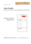
5.10.4 Read initial microstructure from a file.
The starting grain structure can also be read
from an ASCII file which will be interpreted as a
map of domain displaying the grains' number
(similarly to the 'korn' output) or marking the
interfaces (similar to the ‘phase’ output when
only one phase is present).
The user has to supply the name of the file, the
dimensions of the map being read (which
doesn’t
have
to
be
the
same
as
the
simulation’s), the number of grains actually read
in, the type transformation to be applied to the
data set (transposed and / or flipped, ‘phase to
grain’ or none), and the number of points it
contains (which can be different from the
Driving File
...
# Grain input
# ===========
# Type of grain positioning ?
# Options: deterministic
random
from_file
from_file
# File for grain properties
Microstructure.txt
# Read grain properties from a file?
# Options:
input
from_file
input
# Number of grains at the beginning?
49
# Treatment of data?
# (none, 1D, flip (bottom<->top), or transpose)?
transpose
# AnzX for initial microstructure?
500
# AnzZ for initial microstructure?
400
# Phase number?
(integer)
1
...
simulation domain). All geometric information
concerning the grains is obviously already supplied, so the user only has to specify the other relevant
grain properties: phase, stored energy, orientation, etc. Please see the corresponding section in the
“Fully Answered Questions” (paragraph 10.3), and the “grain growth” standard examples can also be
looked-up as a reference.
MICRESS user’s manual
26 / 98
Driving files
5.11 Nucleation parameters.
Afterwards nucleation parameters can be defined, the first of them being a flag for nucleation, which
can be set to 'no_nucleation' to disable further nucleation. If so, the following inputs are skipped (as
they are not relevant).
The first of these parameters is a flag
causing an additional output to be
written out when nuclei are set (or a
phase disappears). The next input is
the number of type of seeds
For each of these types of seeds,
their ‘position’, namely ‘bulk’, ‘region’,
’interface’,
‘junction’
(higher-order
junction), or ‘quadruple’ has to be
specified.
Unless
keyword
‘restrictive’
the
additional
is
specified,
triple-junctions are considered to be
also part of the binary interfaces, and
the interfaces are also treated as
pertaining to the bulk. If a nucleation
region is requested the user should
then define it by its coordinates (in
micrometers).
Then the phase of the seeds and the
matrix phase for nucleation have to
be specified. If the seeds are to be set
in the bulk or in a region, the user
also has to specify which nucleation
model
has
to
be
used:
‘seed_undercooling‘ (i.e.: a new grain
is
set
as
undercooling
soon
is
as
a
critical
reached)
or
‘seed_density‘ which is more suitable
when a heterogeneous nucleation
situation is considered. The former is
used by default for nucleation at the
Driving File
...
# Data for further nucleation
# =================
# Enable further nucleation?
# Options:
nucleation
no_nucleation
nucleation
# Additional output for nucleation?
# Options:
out_nucleation
no_out_nucleation
no_out_nucleation
# Data for further nucleation
# ----------------------------# Number of types of seeds?
1
# Input for seed type 1:
# ------------------------# Type of 'position' of the seeds?
# Options: bulk region interface triple quadruple
junctions
# Phase of new grains?
2
# Reference phase?
1
# maximum number of new nuclei 1?
250
# Grain radius [micrometers]?
0.0000
# Choice of growth mode:
# Options: stabilisation analytical_curvature
stabilisation
# min. undercooling [K] (>0)?
50.000
# Shield effect:
# Shield time [s] ?
20.000
# Shield distance [micrometers]?
2.5000
# Nucleation range
# min. nucleation temperature for seed type 1
1000.0
# max. nucleation temperature for seed type 1
1200.0
# Time between checks for nucleation? [s]
1E-1
# Max. number of simultaneous nucleations?
# ----------------------------------------------# (set to 0 for automatic)
0
# Shall metastable small seeds be killed?
# -------------------------------------------# Options:
kill_metastable
no_kill_metastable
no_kill_metastable
#
...
[restrictive]
interfaces and higher-order junctions.
For the sake of brevity, only the ‘seed_undercooling‘ case will be described here.
MICRESS user’s manual
27 / 98
Driving files
In the case of nucleation at an interface, a substrate phase can be specified to take into account the
curvature undercooling: this option can be disabled by specifying the reference phase as a substrate
phase.
Then the maximum number of these seeds
has to be specified (please note that this total
might not be reached if the conditions do not
allow it). Their radius can be set: it should be
chosen carefully as the nuclei might be off
equilibrium in the phase-field description, this
MICRESS on-screen output
...
# Beginning of initialization
# ================
...
# Critical grain radius:
# of Phase 2 in Phase 1 = 2.50000 / dT_unt [micrometers]
...
value should not be so low to let them
redissolve. An indicative value (based on the of critical nucleation radius for homogeneous nucleation)
is given on-screen at the beginning of the simulation (when Thermo-Calc™ coupling is not activated).
A workaround is to set the ‘growth mode’ of the seeds to 'stabilisation', which will free then from the
curvature term of the phase-field equation until they reach a sufficient size.
Then the value of the constitutional undercooling triggering nucleation (in Kelvin, counted as positive),
or the minimum stored energy (in J.cm-3), if recrystallisation is taken into account for any phase has to
be specified. The ‘shield effect’ data are to be set: they include the ‘shield time’ (latency time after new
nuclei are sets, during which nucleation is temporarily disabled around them), and shield distance
(radius of the zone centred on the nuclei in which nucleation is disabled, in µm). These parameters
can have a quite a dramatic influence on the resulting microstructure.
If applicable the way of setting the seeds orientation has to be specified: it can either be ‘random‘, ‘fix‘,
‘range‘, or ‘parent_relation‘: this should hopefully be self-explanatory. If the grains’ phase is to be
categorised, the number of distinct ‘categories’ (orientations) into which the grains have to be sorted
can be specified
Minimum and maximum nucleation temperatures for each seed type to be nucleated have to be
specified afterwards.
Then the (simulation) time (in seconds) between checks for nucleation has to be input, the main
influence of this parameter is to speed-up the calculation: it can therefore be left to 0 (automatic) as a
first try.
Some noise can be added to the calculation of the driving force for nucleation (flag ‘nucleation_noise‘
‘no_nucleation_noise‘), if set, the coefficient for the noise level and a seed for the random number
(
(
generator will be asked. The noise is applied as ΔG ← 1 + k × random − 1
2
))ΔG
(where
0 ≤ random ≤ 1 is the output of the random number generator and ΔG the driving force for nucleation:
constitutional undercooling or stored energy).
MICRESS user’s manual
28 / 98
Driving files
In some cases the user might wish to limit the number of nucleations events per call to the nucleation
routine: this can be done afterwards.
In some cases, ‘stabilised’ nuclei can reach a metastable state at which they do not grow any more
(as they are meant to), but nevertheless do not vanish because the weighting of the curvature term in
the phase-field equation slows their disappearance to a standstill. It is possible to terminate the nuclei
that have not grown enough between two consecutive call to the nucleation routine (hence the
importance of this parameter in this case), by enabling 'kill_metastable', this flag can also be set to
'no_kill_metastable'.
5.12 Phase interaction data.
Physical data for the interaction of
Driving File
each phase with the others are
entered afterwards. Each of this can
be disabled by setting the parameter
to ‘no_’.
Solid-state
inter-action
between
grains of the same phase can be
simulated when the interaction of
one phase with itself is enabled.
The surface energy and kinetic
coefficient are to be set. The
mobility and surface energy can be
input as constant values or treated
as
temperature-dependant
parameters, in which case a text file
describing this dependency has to
be specified. These files should
...
# Phase interaction data
# ==============
#
# Data for phase interaction 0 / 1:
# -----------------------------------# Simulation of interaction between phase 0 and 1 ?
# Options: phase_interaction no_phase_interaction
#
[standard|particle_pinning|solute_drag]
no_phase_interaction
[…]
# Data for phase interaction 1 / 1:
# -----------------------------------# Simulation of interaction between phase 1 and 1 ?
# Options: phase_interaction no_phase_interaction
#
[standard|particle_pinning|solute_drag]
phase_interaction
# Type of surface energy definition between phases 1 and 1?
# Options: constant temp_dependent
constant
# Surface energy between phases 1 and 1? [J/cm**2]
1.00000E-05
# Type of mobility definition between phases 1 and 1?
# Options: constant temp_dependent sd_kth dg_dependent
constant
# Kinetic coefficient mu between phases 1 and 1? [cm**4/(Js)]
1.00000E-05
#
...
consist of two columns: the first
being the temperature and the second the value of the corresponding mobility or surface energy at this
temperature. A linear interpolation will be performed between the values supplied by the user. Please
note that the check for the compliance of the mobility, surface energy and constant time-step with the
stability criteria has been disabled in this case.
Another option for the mobility is the solute-drag model from KTH where an effective mobility
dependant on the driving force is used, see article [14] of the references.
MICRESS user’s manual
29 / 98
Driving files
An additional flag can also be set to specify the interaction model to be used: standard (i.e.: standard
phase-field equation), particle pinning, or solute drag. These two models are described in the articles
[6] and [7] of the references, they are based on a two-steps hysteresis description of the mobility,
respectively as a function of interface velocity (for solute drag) or driving force (for particle pinning).
The solute drag effect is considered to be dependent on the mobility of the interface. To model this
behaviour three parameters are necessary: the reduction of the mobility (drag factor, coefficient (<1)
correcting the mobility at low velocities), the critical velocity setting the limit for solute drag, and a
transition range within which the mobility changes linearly between the mobility values with and
without solute drag.
Particle pinning is modelled as a dependence of the mobility on the driving force calculated from the
local curvature. Two parameters are needed: the minimal mobility and the critical curvature.
A few more parameters have to
be
specified
for
interactions
between different phases: first the
‘delta G’ options, which control
respectively the averaging along
the normal to the interface, cutting
off the driving force, and the
‘smoothing’. They are to be input
in one line with keywords, what is
not specified will be set to default,
if everything should be set to
default, use 'default' as a place
holder.
For
information,
the
effective values are mirrored right
after the input.
The averaging factor, with the
keyword 'avg': this is a value
between 0 (no averaging) and 1
(average to the infinite), with 0.5
Driving File
...
# Phase interaction data
# ==============
#
# Data for phase interaction 0 / 1:
# --------------------------------# Simulation of interaction between phase 0 and 1 ?
# Options: phase_interaction no_phase_interaction
#
[standard|particle_pinning|solute_drag]
phase_interaction
# 'DeltaG' options: default
#
avg ... [] max ... [J/cm**3] smooth ... [degrees]
avg 1 max 20
# I.e.: avg +1.00 smooth +45.0 max +2.00000E+01
# Type of surface energy definition between phases LIQUID and 1?
# Options: constant temp_dependent
constant
# Surface energy between phases LIQUID and 1? [J/cm**2]
2.04000E-05
# Type of mobility definition between phases LIQUID and 1?
# Options: constant temp_dependent sd_kth dg_dependent
constant
# Kinetic coefficient mu between phases LIQUID and 1? [cm**4/(Js)]
4.00000E-03
# Is interaction isotropic?
# Options: isotropic anisotropic
anisotropic
# static anisotropy coefficient? (< 1.) (changed!!!)
0.3000000
# kinetic anisotropy coefficient? (< 1.)
0.3000000
#
for averaging over the interface's
length. This feature is only activated if the “averaging of the driving force along the normal to the
interface” has been enabled, and is meant to help stabilising the interface.
Compatibility note: this input has the same purpose as the previous averaging length, but a different
definition: averaging factor ≈
MICRESS user’s manual
averaging length
interface thickness + averaging length
30 / 98
Driving files
The directional averaging can be specified via the keyword 'smooth': this enables averaging not only
along the normal itself, but also with some deviation, which helps minimising the effects of the grid
anisotropy. Please note that directional averaging is enabled only when averaging (along the normal
to the interface) is. It can also be disabled by setting it to a negative value.
The maximal driving force allowed (value above which the driving force will be cut-off), can be
specified with the keyword ‘max’: this is useful to shrug off some temporary problems during transients
or fluctuations. Just omit the input to disable (this is the default!), as a negative value will 'blank' 'ΔG',
i.e.: only take into account the curvature part of the driving force...
The description of the interaction between an 'anisotropic' phase and an 'isotropic' one also includes a
flag for the anisotropy, and if this is switched on, the static and kinetic anisotropy coefficients have to
be specified.
5.13 Diffusion data.
The
diffusion
parameters
have
to
be
specified. First the number of dissolved
constituents is set.
Afterwards the user has to choose whether
the concentrations will be set in atom or
weight percents.
For each component and phase the diffusion
flag should be set: the available options are
'diff',
'no_diff',
'database_blobal',
'infinite',
'stoichio',
database_local',
and
'multi'. The meaning of the first four should
be
self-explanatory.
Setting
'database'
means that the diffusion coefficients will be
calculated by Thermo-Calc™ (via its TQ
interface): this is only possible when the
‘GES-file’ used also contains mobility data.
'multi'
means
that
the
complete Fick-
Driving File
...
# Concentration data
# ============
# Number of dissolved constituents? (int)
2
# Type of concentration?
# Options:
atom_percent (at%)
#
weight_percent (wt%)
weight_percent
#
# Options: diff
no_diff
infinite
multi
#
database_global
database_local
#
[+b] for grain-boundary diffusion
# ('multi' can be followed by a string of "n", "d", "g", or "l",
# to describe each contribution: respectively no diffusion,
# user-defined diffusion coefficient, and 'global' or 'local'
# value from database, the default is global values from
database).
# How shall diffusion of component 1 in phase 0 be solved?
no_diff
# How shall diffusion of component 1 in phase 1 be solved?
diff
# Diff.-coefficient:
# Prefactor? (real) [cm**2/s]
0.23400
# Activation energy? (real) [J/mol]
1.47700E+05
...
Onsager equations will be solved, including
the so-called ‘off-diagonal terms’ of the diffusion matrix. It is possible to qualify 'multi' and use ‘global’
or ‘local’ diffusion coefficients from a database (‘local’ means that they are linearly interpolated inside
a phase to reflect the influence of composition), user-defined or simply ignored. If 'diff' has been
selected, the pre-exponential factor and its activation energy (which can be set to 0 for no temperature
MICRESS user’s manual
31 / 98
Driving files
dependence) of the diffusion coefficient have to be specified. In the case of a stoichiometric phase a
diffusion coefficient can nevertheless be input for numerical reason (it can be set 0 if not needed).
It is also possible to request enhanced diffusion at the grain boundaries with “+b” followed by a string
consisting of “b” and “n” (to respectively en- or disable this feature for the corresponding grain
boundaries). When this feature is used, the user is prompted for the correction of the activation energy
at the interface, and the physical width of the interface.
5.14 Phase diagram data.
The first information required is a list of the
stoichiometric components.
The user then has to specify whether
Thermo-Calc™ coupling is to be used (as
opposed to the input of a linearised phase
diagram), which can be respectively set with
'database' or 'no_database'.
The following depends heavily on this choice
and has therefore been split in two sub-
Driving File
...
#
# Phase diagram - input data
# =================
#
# List of phases and components which are stoichiometric:
# phase and component(s) numbers
# End with 'no_more_stoichio' or 'no_stoichio'
no_stoichio
#
# Is a thermodynamic database to be used?
# Options: database no_database
no_database
#
...
sections.
MICRESS user’s manual
32 / 98
Driving files
5.14.1 Linearised phase diagram.
If the Thermo-Calc™ coupling (via its TQ
interface) is switched off (or a phase
interaction is set to ‘linear’), the values
relative to the linearised phase diagram
have to be set.
They have to be input by pair-wise
relation: data related to the equilibrium of
phase 0 and 1 (i.e.: phase 1 and liquid),
0 and 2, and so on. When all relations
concerning the liquid phase have been
described, those describing solid phases’
equilibrium have to be input: 1 and 2, and
others
if
needed.
(The
equilibrium
between phases which are not interacting
doesn’t need to be described).
They include the reference temperature
(at
which
the
linearization
Driving File
...
# Is a thermodynamic database to be used?
# Options: database no_database
no_database
# Input of the phase diagram of phase 1 and phase 2:
# ----------------------------------------------------------# Temperature of reference point? [K]
1149.9000
# Entropy of fusion between phase 1 and 2 ? [J/(cm**3 K)]
0.14900
# Input of the concentrations at reference point
# Concentration of component 1 in phase 1 ? [wt%]
0.32000E-02
# dissolved concentration in phase 2 ? [wt%]
0.15811E-03
# Concentration of component 2 in phase 1 ? [wt%]
0.17399
# dissolved concentration in phase 2 ? [wt%]
0.96288E-01
# Input of the slopes at reference point
# Slope m_iPh = dT/dC_iPh relative to component 1 ? [K/wt%]
-386.5673523
# Slope m_jPh = dT/dC_jPh relative to component 1 ? [K/wt%]
-8036.549805
# Slope m_iPh = dT/dC_iPh relative to component 2 ? [K/wt%]
-39.82677078
# Slope m_jPh = dT/dC_jPh relative to component 2 ? [K/wt%]
-73.34864807
was
performed), the entropy of transformation,
the concentration of each components in the
considered phases, and the corresponding
slopes.
For multi-component systems the descriptions
becomes lengthier, but the formalism is the
same.
MICRESS user’s manual
33 / 98
Driving files
5.14.2 Thermo-Calc™ coupling via its TQ interface.
To use Thermo-Calc™ coupling, a ‘GES-file’
is needed, this is the first input to be supplied.
The frequency for complete relinearization
has to be set.
Then, in a similar way to what is done without
coupling, the phase interactions are gone
through: each equilibrium can be described by
the TQ interface of Thermo-Calc™ or with a
linearised phase diagram (in which case the
input is similar to 5.10.1): this is set with ‘TC’
or ‘linear’.
If
Thermo-Calc™
is
used,
a
maximum
temperature deviation for re-linearization has
to be specified. Setting a high value speeds
up the calculation by limiting the number of
calls to the TQ library (at the expense of
precision). An input of ‘-1’ can be used to
switch off the relinearisation triggered by
temperature deviation.
The
Thermo-Calc™
index
of
each
(MICRESS) component and phase is then to
Driving File
...
# Is a thermodynamic database to be used?
# Options: database no_database
database
# Name of Thermo-Calc *.GES5 file without extension?
GES_Files/Al_Cu
# Frequency for complete relinearization [s] =
100.
# Input of the phase diagram of phase 0 and phase 1:
# ----------------------------------------------------------# Which phase diagram is to be used?
# Options: database linear
database
# Maximal allowed local temperature deviation [K]
-1.
# The database contains the following components:
# AL
# CU
# Specify relation between component indices Micress -> TC!
# The main component has in MICRESS the index 0
# Thermo-Calc index of (MICRESS) component 0?
1
# Thermo-Calc index of (MICRESS) component 1?
2
# The database contains 2 phases:
# LIQUID
# FCC_A1
# Specify relation between phase indices Micress -> TC!
# The matrix phase has in MICRESS the index 0
# Thermo-Calc index of the (MICRESS) phase 0?
1
# Thermo-Calc index of the (MICRESS) phase 1?
2
# Molar volume of (MICRESS) phase 0? [cm**3/mol]
10.
# Molar volume of (MICRESS) phase 1? [cm**3/mol]
10.
# Temperature at which the initial equilibrium
# will be calculated? [K]
914.
be set. MICRESS displays at run-time the list
of components and phases available in the selected 'GES-file'.
Afterwards the user is prompted for molar volume of each phase.
The final input of this section is the temperature for the initialisation by Thermo-Calc™ of the
interactions of phases present at the beginning of the simulation.
It is possible to tweak the size of TQ’s
workspace by adding an optional line starting
with the keyword ‘wokspace_size’ followed by
the requested size in kilo-bytes after the
specification of the ‘GES-file’. The following
input remaining unchanged.
MICRESS user’s manual
Driving File
...
# Is a thermodynamic database to be used?
# Options: database no_database
database
# Name of Thermo-Calc *.GES5 file without extension?
GES_Files /Fe_C_Mn_Si_P
# TQ's 'workspace' size? (in kilo-bytes)
workspace_size 100000
...
34 / 98
Driving files
5.15 Initial concentrations.
Input of the initial concentration: three
possibilities are available: explicitly
setting the concentration for each
phase (with ‘input’), specifying only the
initial concentration of one phase, and
using the equilibrium concentrations for
the other phases is also possible (with
‘equilibrium’). Finally, similarly to what
is done for the initial grain structure,
the initial concentration field can be
read from a file (with ‘from_file’).
If
‘input’
is
used,
the
initial
Driving File
...
#
# Initial concentrations
# ======================
# How shall initial concentrations be set?
# Options: input equilibrium from_file
[phase
input
# Initial concentration of component 1 in phase 0?
0.E+0
# Initial concentration of component 1 in phase 1?
3.299999982E-3
# Initial concentration of component 1 in phase 2?
1.999999955E-2
# Initial concentration of component 2 in phase 0?
0.E+0
# Initial concentration of component 2 in phase 1?
0.173999995
# Initial concentration of component 2 in phase 2?
0.400000006
#
...
number]
[wt%]
[wt%]
[wt%]
[wt%]
[wt%]
[wt%]
concentrations of each constituent in
each phase have to be selected, even for phases which might not be initially present (in this case, this
value is of little significance).
If ‘equilibrium’ is chosen: the concentration only have to be set for a reference phase, which is by
default the liquid, but can be any other one present at the beginning (its index should then be specified
in the same line).
5.16 Elastic material data
This
only
applies
Driving File
and
‘stress’
‘stress_coupled’ simulations. The first
input is the phase number of a matrix
phase. The strain and the calculation
of the Eigenstrains will be referenced
to this phase. Then for each phase its
molar
volume
and
three
tensor
coefficients of Hooks matrix in Voigtnotation
necessary
C11,
C12,
input.
C44
are
With
the
these
parameters isotropic and cubic lattice
symmetries can be represented.
MICRESS user’s manual
...
# Input of materal data for elastic calculation
# =============================================
#
#
# Phase number of the matrix phase (int)
1
# Abstraction of the 3D continuum
#
Options: plane_stress plane_strain
plane_stress
#
#
# phase 0
# ------# molar volume [cm**3], phase 0
7.18240023
# Elastic components (Voigt-notation)
# C11 [MPa] ( >0 )
, phase 0
23300.
# C12 [MPa] ( >0, <C11 ), phase 0
13300.
# C44 [MPa] ( >0 )
, phase 0
11600
...
35 / 98
Driving files
5.17 Temperature data.
In
the
case
of
temperature
coupling, the phase equilibrium
can be described only with the
equilibrium temperature and the
entropy of fusion.
The other inputs are the heat
conductivity ( λ ), heat capacity
( ρC p ) and latent heat for each
phase.
The two former can be input as
constant values or treated as
temperature-dependant
parameters, in which case a text
file describing this dependency
has to be specified. These files
should consist of two columns: the
first being the temperature, and
the second the value of the
corresponding material property at
this
temperature.
A
linear
interpolation will be performed
between the values supplied by
the user.
MICRESS user’s manual
Driving File
...
#
#
# Phase diagram - input data
# =================
#
# A description of each pairwise thermodynamic
# interaction has to be specified.
#
# Equilibrium temperature (real) [K] between 0 and 1
1000.000
# Entropy of fusion between phase LIQUID and 1 ? (real) [J/(cm**3 K)]
0.5000000
#
# Temperature Data
# ===========
# Type of thermal conductivity definition for phase 0 ?
# Options: constant
temp_dependent
constant
# Thermal conductivity of phase 0 ? (real) [W/cm/K]
0.5000000
# Type of thermal conductivity definition for phase 1 ?
# Options: constant
temp_dependent
constant
# Thermal conductivity of phase 1 ? (real) [W/cm/K]
0.5000000
# Type of specific heat capacity definition for phase 0 ?
# Options: constant
temp_dependent
constant
# Specific heat capacity of phase 0 ? (real) [J/cm**3/K]
1.000000
# Type of specific heat capacity definition for phase 1 ?
# Options: constant
temp_dependent
constant
# Specific heat capacity of phase 1 ? (real) [J/cm**3/K]
1.000000
# latent heat for phase interaction 0 / 1?
(real) [J/cm**3]
10.00000
#
...
36 / 98
Driving files
5.18 Latent heat parameters.
In this section, specific input
Driving File
data for the release of latent
...
#
# Parameters for latent heat
# ==========================
# Simulate release of latent heat?
# Options:
lat_heat
lat_heat_3d [matrix phase]
no_lat_heat
lat_heat
# Enthalpy of phase 0? ([J/cm^3])
0.E+0
# Specific heat capacity (Cp) of phase 0? ([J/(cm^3*K)])
2.43
# Enthalpy of phase 1? ([J/cm^3])
-1231.
# Specific heat capacity (Cp) of phase 1? ([J/(cm^3*K)])
2.43
# Enthalpy of phase 2? ([J/cm^3])
-1231.
# Specific heat capacity (Cp) of phase 2? ([J/(cm^3*K)])
2.43
#
...
heat are defined, which can be
simulated (or not) by specifying
‘lat_heat’ to or ‘no_lat_heat’.
Then, the enthalpy of each
phase (including the liquid), as
well as its specific thermal
capacity has to be specified.
As the time to reach thermal
equilibrium
negligible
is
considered
compared
to
the
characteristic times for diffusion
the release of latent heat is treated as a 'global warming': the temperature of the whole simulation
domain being raised uniformly.
If the release of latent heat is enabled, the specification of the variation of temperature is made via the
input of a heat flux, and the ‘Moving frame’ feature is automatically disabled (see hereafter).
5.19 Boundary conditions.
Some other conditions have to be set.
The
first
of
those
are
related
Driving File
to
temperature: the initial temperature: the
type of variation (which should be left to
‘linear’), the number of transition points, as
the temperature conditions can be set by
intervals. Then for each of these transition
points (including t=0), the time (except, of
course for t=0), the temperature at the
bottom and the temperature gradient (in
the z direction). The temperature and
temperature
interpolated
gradient
between
points.
MICRESS user’s manual
are
linearly
these
transition
...
#
# Boundary conditions
# =============
# Type of temperature trend?
# Options: linear
linear_from_file
sinus
linear
# Number of connecting points? (integer)
2
# Initial temperature at the bottom? (real) [K]
1150.
# Temperature gradient in z-direction? [K/cm]
0.E+0
# 1 Connecting point, time t [sec]?
2.5
# 1 Connecting point, temperature
1125.
# 1 connecting point, temp. gradient in z-direction [K/cm]
5.
# 2 Connecting point, time t [sec]?
7.5
# 2 Connecting point, temperature
1000.
# 2 connecting point, temp. gradient in z-direction [K/cm]
25.
...
37 / 98
Driving files
It is also possible to read this information from a file consisting of three columns storing respectively
the time in seconds, the temperature at the bottom in
Driving File
Kelvin, and the gradient in Kelvin per centimeter.
Finally, is also possible to describe the temperature
evolution by a single cooling rate and temperature
gradient, in which case the number of transition points
should be set to 0
If the release of latent heat is enabled, a heat flux (in
Js/cm3) has to be specified instead of a temperature
(or cooling rate).
...
#
# Boundary conditions
# =============
# Type of temperature trend?
# Options: linear
sinus
linear
# Number of connecting points? (integer)
0
# Initial temperature at the bottom? (real) [K]
1155.
# Temperature gradient in z-direction? [K/cm]
0.E+0
# Cooling rate? [K/s]
-25.
...
Then the 'moving frame' options have to be set: this
feature is very useful for simulations related to directional solidification, as it allows the actual solving
to be done on only part of the simulation domain (therefore reducing CPU time). If the flag
'moving_frame'
is
not
set
to
'no_moving_frame', the user is prompted
for the criteria causing points to be shifted
out of the simulation domain: this can be
‘temperature’ or ‘distance’. In the case of
‘temperature’, it is linked to a temperature
below which the points have to be shifted
out
of
the
simulation
domain.
For
‘distance’, it is the minimal distance
between the solid phases and the top of
the simulation domain. In both cases, the
Driving File
...
# Moving-frame system in z-direction?
# Options:
moving_frame
no_moving_frame
moving_frame
# Should the distance or the bottom temperature be
# used as criterion for moving frame?
# Options: distance temperature
distance
# At which distance from the upper boundary the frame should
# be moved? (real) [micrometers]
200.0000
# Store data shifted out of moving-frame system?
# Options:
out_moving_frame
no_out_moving_frame
no_out_moving_frame
...
corresponding value has to be input
afterwards.
Saving the data related to these points is directed by the
'out_moving_frame' flag: creating (or not) 'Gesamt' (global) data for
all selected outputs: these files have 'G' appended to their 'root name'
(i.e.: 'Simulation.phas' and 'SimulationG.phas' under Unix).
The assumptions made to simulate the release of latent heat are
deemed to be incompatible with the use of the moving frame feature,
it is therefore disabled in this case.
MICRESS user’s manual
38 / 98
Driving files
The boundary conditions
Driving File
should be set for phasefield,
concentration,
temperature
and
displacement
field
depending on the type of
coupling which had been
defined in the beginning.
The boundary conditions
can be insulation, periodic
...
# Boundary conditions for phase field in each direction
# Options: i(insulation) s(symmetric) p(periodic/wrap-around) g(gradient) f(fixed)
# Sequence: E W (N S, if 3D) B T borders
pppp
#
# Boundary conditions for concentration field in each direction
# Options: i(insulation) s(symmetric) p(periodic/wrap-around) g(gradient) f(fixed)
# Sequence: E W (N S, if 3D) B T borders
pppp
# Unit-cell model symmetric with respect to the x/y diagonal plane?
# Options: unit_cell_symm no_unit_cell_symm
no_unit_cell_symm
...
(wrap-around), symmetric
(the domain boundary being treated as a local symmetry plane), gradient or fixed (a fixed value is set
for the corresponding field at the corresponding interface) in the case of phase field, temperature and
concentration.
Additional
boundary
conditions
are
Driving File
required in case of stress coupling, the
available options are ‘constant_volume’
(zero displacement of all boundaries),
‘free_expansion‘
(bottom
left
corner
fixed, free expansion in all directions)
and ‘parallel_expansion‘ (bottom left
...
# Boundary condition for elastic stress calculation
# Options: constant_volume normal_expansion free_expansion
#
fix_isostatic_pressure fix_normal_pressure
#
fix_isostatic_strain fix_normal_strain
fix_isostatic_strain
# Isostatic strain? +/- (real) [%]
1
...
corner fixed, free expansion along main
axes). Furthermore external stress and strain acting on the simulation domain can be defined. The
boundary conditions are ‘fix_isostatic_pressure‘, ‘fix_isostatic_strain’, ‘fix_normal_pressure’ and
‘fix_normal_strain’, accordingly. For the ‘isostatic’ cases either the normal pressure at the domain
boundaries or the normal displacement are fixed. The values should be specified in a second line (real
numbers, units are [MPa] or [%], respectively. The ‘normal’ variants allow the definition of normal
displacement or normal stress in each direction separately. In all cases the domain will expand
according to the option ‘parallel_expansion‘.
An attempt can also be made to try to keep some kind of symmetry with respect to the x/y diagonal:
'unit_cell_symm' and 'no_unit_cell_symm' are the available options.
MICRESS user’s manual
39 / 98
Driving files
Then,
the
maximum
number
of
concentration solving per phase-field
iteration has to be entered (in the case
of concentration coupling). This input
is not required with automatic timestepping. There is no strong influence
on the results or performance. If the
value is too small, a warning is issued.
Driving File
...
#
# Other numerical parameters
# =================
# Maximum number of calls of the concentration solver per iteration?
500
# Phase minimum?
9.999999747E-5
# Interface thickness (in cells)?
7.5
#
...
Φmin should be specified here, it is a
deviation limit for the phase-field parameter below which the cell is not considered to be in the
interface any more but in a bulk region (be it liquid or solid).
The interface thickness (in cells) also has to be input here.
In case of stress coupling the convergence criteria for the iterative BiCGstab matrix solver as well as
an upper limit (maximum number) of iterations has to be defined. In the input line for the maximum
number of iterations a second integer input is possible. The number is set to 20 by default and
specifies the maximum number of iterations allowed for achieving a good solution for the quasi-static
equilibrium. In most cases default settings are sufficient.
MICRESS user’s manual
40 / 98
Known issues
6
Known issues.
6.1 Problems with some Linux distributions.
It is currently not possible to run MICRESS® with some Linux distributions: this is mostly due to
problem with the licensing package used in MICRESS (FLEXLM™), here is a comment made on
Macrovision’s website:
“Our experience with Linux leads us to believe that it is not the most infallible operating
system that we support. This is likely due to the fact that the operating system can be easily
customized - presenting advantages and disadvantages.
We have found that each new
release of Linux isn't necessarily backwards compatible although each new release does
include important enhancements.”
6.2 Restarting simulations.
The ‘restart’ feature was found not to be entirely accurate in some cases (last digit variations),
especially with the coupling to Thermo-Calc™ (via its TQ interface).
6.3 μ(T) and stability criteria.
The check for the compliance of the mobility, surface energy and the constant time-step with the
stability criteria has been disabled in the case of a temperature or driving-force dependant mobility.
Please use automatic time-stepping in this case.
6.4 Nucleation of liquid.
It is currently not possible to simulate the nucleation of liquid with MICRESS®.
6.5 Image drivers for Display MICRESS.
Unfortunately no PNG image driver could be implemented for the PC version of Display MICRESS, so
instead of 'Transparent PNG' and 'Opaque PNG' the two options available in windows environment are
'Portrait GIF' and 'Landscape GIF'.
MICRESS user’s manual
41 / 98
Post-processing
7
Post-processing.
MICRESS generates output files for the solutions of different field variables in a binary format. The
solutions for the individual time steps are concatenate in one file. For evaluation and visualisation of
the output files different post-processing tools are available. A brief description is given in this chapter.
7.1 Available post processing tools.
Display MICRESS:
Visualisation tool for MICRESS result files.
Transfer MICRESS:
Filter for MICRESS result files.
DP MICRESS:
Bundle of the two previous executables.
(Note: to increase confusion and generally confound the reader as
much as possible, the DP MICRESS binaries are nevertheless
called
Display MICRESS
and
the
graphical
interface
to
Display MICRESS is called DP_MICRESS).
7.2 Display MICRESS.
Display_MICRESS (DP_MICRESS) is a post-processing tool with a wide span of possibilities, ranging
from basic display and image output, to advanced features such as zooming, multiple display, build-in
four-folded symmetry, animation and ‘Virtual EDX’. It can also handle several files simultaneously.
It can read results file in binary (single and double precision, native or not) and ASCII, compressed or
not, as well as perform conversions between these formats.
Libraries:
Display MICRESS relies on the following libraries:
PGPlot (www.astro.caltech.edu/~tjp/pgplot) for all graphical operations.
PNG (www.libpng.orgl) for images output.
http://www.zlib.net is used for compression, by the PNG library and for compressing files.
GrWin (http://spdg1.sci.shizuoka.ac.jp/grwinlib/english) is used as a screen driver for PGPlot
under Windows.
DP_MICRESS, the graphical user interface to Display MICRESS:
ª
ª
ª
ª
ª is written in Perl (www.perl.org).
ª uses extensively the Perl/Tk module (www.ni-s.u-net.com).
ª and is 'packed' as an executable with PAR (par.perl.org).
MICRESS user’s manual
42 / 98
Post-processing
7.2.1 Running Display MICRESS.
Display MICRESS can be called from a shell, providing the name of the result file(s) to be displayed (it
does not allow switching between files, meaning it shall be restarted to display another file).
It can, for example, be called with:
DP_MICRESS Test.phas
(if no argument is provided, a summary of command line-options is returned).
Command-line options:
Main command-line options:
Ö
Ö
Ö
Ö
Ö
Ö
-b: results in binary (single-precision).
-z: read compressed results.
-3,-4,-9: respectively three-, four- or ninefolded symmetry.
-f: read automatic min./max. from the first
time-step.
--Min:value –Max:value: explicitly specify
the min. and max. to use.
-m: multiple results: specify the number of
result files (integer value following 'm',
ex.: -m6).
Ö
Ö
Ö
Ö
Ö
Ö
-p: divide display in panels, row major (two
integers separated by 'x' following 'p',
ex.: -p2x3).
-q: divide display in panels, column major
(ex.: -q2x3).
-g: read run-time instructions from standard
input (to allow piping from GUI device).
-t: Transfer MICRESS (converts file).
--Animate: animate to the end.
--Help: print a list of all available commandline options.
Default settings:
Ö
Ö
automatic min./max. from the whole file.
number of panels fits the nb. of solutions.
Ö
no graphical user interface (when called
from the command line).
Multiple display: this feature is restricted to results files with the same geometry.
Compressed files: the whole files are decompressed to temporary files which are erased when the
program is exited, it is therefore preferable to close Display MICRESS 'nicely' (i.e.: no interruption), to
avoid leaving those files in the working directory.
Non-native files: Display MICRESS can handle ‘non-native’ binary results, but the necessary on-thefly conversion nevertheless takes time: converting the files is often a reasonable option. It is also
impossible to display files with different ‘endian-ness’.
Transfer MICRESS:
This tool converts results file to and from the following formats: binary (both single and
double precision) and ASCII, compressed or not. The ASCII format is useful to transfer results
between platforms. Transfer MICRESS can also rename MICRESS® result files using Irix or Windows
naming conventions.
It can, for example, be called with:
DP_MICRESS -t Test_Binary.phas Test_ASCII.phas
(if no argument apart from '-t' is provided, a summary of command line-options is returned).
Command line:
DP_MICRESS -t [options] [-i]Input_File [[-o]Output_File]
(-i and -o can omitted if file names are specified in that order the output name can be omitted
altogether if it is the same as the input).
MICRESS user’s manual
43 / 98
Post-processing
Available options:
Ö
Ö
Ö
Ö
Ö
Ö
Ö
Ö
-a: input file in ASCII.
-d: input file in double precision.
-e: input file in binary (single precision).
-y: compressed input file.
-b: output file in binary (single precision).
-f: output file double precision.
-c: output file in ASCII.
-z: compress output file.
Ö
Ö
Ö
Ö
Ö
-g: input is a geoF file.
-w: transfer whole set of results.
-k: remove output from result file (ex.: -k5 to
remove fifth output).
-l: remove sequentially from result file
(ex.: -l5 -l7to remove 5th and 7th outputs).
-r: rename set of results from UNIX's
naming to Windows' (or vice-versa).
Default:
Ö
‘plain’ file in binary (not compressed).
Ö
output file in ASCII (not compressed).
7.2.2 User interface, typographical conventions.
Display MICRESS has a full-fledged graphical front-end (DP_MICRESS) which also acts as a wrapper
to Display_MICRESS itself. The following describes the use with keyboard shortcuts (via the graphical
front-end or not). All operations can be called by 'hot keys', which are not case dependent, e.g. key 'f'
and key 'F' are considered to be identical.
Keyboard input:
Apart from the alphanumeric characters, the following keys are also available: Escape (erases the
current input) and Tab (validate the current input and go the next, if any).
UNIX (and Linux) environment:
The DP MICRESS interfaces can be called with '-g' flag: it is possible to call it with only this flag, then
an interface to create the command-line is displayed, or with a complete command-line, in which case
only the run-time interface is called.
MS Windows:
Double-clicking a MICRESS result file will start Display_MICRESS with the default settings, otherwise
a 'geoF' file should be double-clicked (to display various files at the same time, or call
Transfer_MICRESS for example), Please see 'Installing Display_MICRESS under Windows'.
Typographical conventions:
Keys to be pressed will be printed in italics bold: example N means press key N (either lower or
upper case). The combination of keys D and E (pressing key D then key E) will be represented by
D+E.
For an improved readability, the corresponding operation will be printed in underlined italics.
Known issues:
When using the graphical user interface, not exiting 'nicely' (i.e.: with the 'EXIT' button) can lead to
complications, please avoid it.
MICRESS user’s manual
44 / 98
Post-processing
7.2.3 Time-step operations.
These include going to the next: N, previous P, last L or first F time-steps. Hopefully, these operations
should be self explanatory.
When several files are displayed simultaneously, these operations can also be applied to a selection
of the results only with respectively M+N, M+P, M+L or M+F.
7.2.4 Scale.
By default minimum and maximum are chosen as the extrema of the whole result file, which implies
that the entire file has to be read (which might take some time for very large simulations), unless the '–
f' option was set from the command line, and then the automatic min. and max. are set from the local
min. and max. of the first time step.
The available options are: user-defined min. and max. (S+M: a secondary window is opened to let the
user modify the min. and max. settings), user-defined range (S+R: similar to the previous, but min. and
max. are set as median value and range), use local min. and max., S+D, which sets the extrema from
what is displayed, which can be only part of the result for the current time-step if the zoom is in use,
and finally revert to automatic (i.e. global) min. and max., S+G (if the '-f' option was used, the file is
then read for the global extrema). S+F explicitly force the file to be re-read to find out the global
extrema.
Note: if several result files are displayed the user will be prompted to select the solutions to which
these operations should be applied to. User-defined settings will affect all solutions which are selected
simultaneously.
7.2.5 Colour scale.
Various colour scales are available in Display MICRESS, the default one being the standard
'Viso heat scale', but a few others are also available. They can be selected with C+1...11, (for example
C+1 sets the (default) 'Viso heat scale', and C+2 a black and white one), C+L loops through the
available colour-scales. To select 'double-digit' colour scale without graphical user interface, press 0:
C+0+1+0 will select the tenth colour scale. The tenth and eleventh colour scales (respectively called
with C+9 and C+010) are 'adaptive' in the sense that they have ranges of colors and / or transition
points whose 'position' in the scale can be reset by the user (according the isoline values).
The brightness and contrast can be fiddled with by pressing C+F, or reset with C+R. This fiddling
feature is performed by resetting the brightness with the normalised x-coordinate of the mouse cursor
on the active image, and the brightness with y-coordinate's. If a GUI device is used, the user has to
click to set the cursor's position after calling this feature.
The colour-scale can also be inverted with C+I.
The minimum and maximum of the colour-scale can be cut-off (i.e.: respectively replaced with black
and white) with C+C. The current colour-scale can also be reset in a stepwise fashion with C+S. It is
possible to specify the number of step with C+U (user-defined), and to toggle on and off the use of this
input with C+T. To break some unfortunate patterns when displaying “grain” output, it can be
MICRESS user’s manual
45 / 98
Post-processing
interesting to use a stepwise colour scale, and randomise it with C+K. These previous features are
unfortunately not available under Windows, due to a 'communication' problem between PGPlot and
GrWin.
7.2.6 Animation.
Display MICRESS supports animation, A+R will display one time step and then automatically switch to
the next, looping over the whole file. Unfortunately, it is not possible to interrupt the animation short of
killing the program. A+E starts an animation to the last output.
The animation settings, display time for each time-step and number of loops can be changed with
A+S. The display time might actually have to be extended, to let the program proceed to the next timestep (in the case of large result files or simultaneous display of several solutions).
7.2.7 View.
This category regroups various operations related to the graphical window settings.
Reset number of panels: V+P: this should be self-explanatory. The display can be restricted to a given
panel with Freeze panel: V+F, this option is only available when a single result file is displayed, all
subsequent display will be made in the corresponding panel. This feature is convenient to visualise in
the same window specific outputs from a simulation. A secondary window is open, displaying the
current panel setting, clicking on one panel selects it, and a second click validates the selection.
Redraw: V+R, which can be useful when the user wants to update the display (for example after
changing some display parameter). An auto-replot feature is also available with V+Q.
Resize: V+S, makes Display MICRESS take into account the possible resizing of the display-window
made by the user, and updates the viewport accordingly. An ‘auto-resize’ feature can also be
switched-on (and off) with V+Z.
Displaying annotations (comments and colour scale) can be set with V+A: four options are available:
comments and colour scale (default), colour scale only, annotations only, or none. The colour scale
can be displayed in a secondary window with V+C. Please note that later changes on the scale won't
be reflected on this display. The annotations can also be positioned to the left and right of the picture
or at the bottom and top, which toggled with V+O (for orientation of annotations), this setting will also
be reflected on the colour scale displayed in secondary windows. The 'thickness' of the colour scale
can be increased with V+T, the font size for the comments will also be modified at the same time.
The default background colour is black but can be switched to white with V+W, which also affects
images output. Please note that writing transparent PNG images with a white background does not
always provide good readability.
Displaying with ‘thin’ 1D results (i.e.: with a large number of cells) can sometimes be a bit
dissatisfactory, toggling on the ‘enhanced 1D’ display mode with V+1 usually helps.
If a “TabF” result file was written, the temperature at the bottom can be displayed with V+K.
Secondary windows can be closed with V+X, meaning the colour-scale, virtual EDX, and scan-point
windows.
MICRESS user’s manual
46 / 98
Post-processing
7.2.8 Display.
The display of length-scale is toggled on and off by D+L, the reference length can be set by default or
chosen by the user with D+M. Letting Display MICRESS select the length to be displayed
automatically ensures that its representation is between one fifth and half of display. By default this
scale is horizontal but it can also be flipped to vertical with D+F.
Known limitation: the display of the length scale is not satisfactory with high zooming, but the results
are anyway deemed not have much meaning at the corresponding resolutions.
The zoom can be called with D+Z, the user then has to define the zoom box (area which will be
displayed afterwards) by setting two (opposite) corners with mouse clicks, once these two points have
been set, the zoom box is drawn, and can be refused by pressing the right mouse button or X (in
which case another zoom box can be set), or accepted by pressing any other key. Zoom out with D+Y,
no progressive zooming out is done, i.e. zoom options are directly reset to their default values (i.e.: 'full
picture'). It is also possible to zoom back with D+X (please note that only one set of zoom settings is
saved…)
If the simulation set-up takes advantage on known symmetries or periodicities of the system and
restricts the domain to part of the ‘real space area’, it is sometimes handy to display respectively three,
four or nine times the simulation domain, with respectively D+3, D+4, D+9. By default the ‘copies’ of
domain are mirrored but they can also be tranlsated which can be toggled on and off with D+C.
To allow readier positioning, a grid can be displayed with D+G. The default number of subdivisions is
5, but this can be adjusted with D+H.
Two additional display modes are available: ‘RGB triangle’ and ‘Miller Indices’ (respectively with D+T
and D+I): both are based on operations on the colour table, and can only be used for all the displayed
results. The ‘RGB triangle’ mode, available with three solutions only, plots a composite of them, where
the colour of a cell is the corresponding intensity of red, green and blue calculated from the displayed
minimum and maximum. The Miller indices output of MICRESS® can also be colour-coded in the
‘traditional’ way (contribution of 001, 011 and 111 orientations). When these display modes are
activated, the corresponding colour-scale is plotted in a secondary window under Irix and Linux,
unfortunately not under Windows (a separate picture can be written out instead).
When two results are displayed, it is possible to display their ‘difference’ with D+D.
It is possible to use a logarithmic scale (D+N): the result data is first cut off to the maximum and
minimum for the scale (which should be positive). It is also possible to take the absolute value of the
results with D+A.
7.2.9 ‘Vector field’.
Display MICRESS also supports vector-field representation (which can be activated with B+2), the last
file displayed being the ‘Y’ component of the vector, and the last-but-one the ‘X’ component (this is
obviously only available with three files at least, when more are displayed, they get the same vector
field). Similarly a 3D vector-field mode is also available (B+N): the X, Y and Z components of the
MICRESS user’s manual
47 / 98
Post-processing
vectors are respectively read from the last three files, the two ones in use depending on the cutting
plane direction (the third one being temporarily ignored). The corresponding settings can be modified
with B+S: they are: the minimum and maximum intensity to be plotted, the ‘thinning’ distance: the
averaging area for which a vector is displayed, and the position of the vector in this area: centred or
not. A ‘vector scale’ representing the maximal intensity can be plotted with B+X. The colour of the
vectors can be controlled with B+B, which loops through black, white and bi-colour.
7.2.10 Isolines.
Display MICRESS supports various isolines options, the first of which is their display, which can
toggled on and off with I+D.
Automatic isolines: I+1...9, automatically adds the corresponding number of isolines, equally spaced
on the scale. Similarly, a user-defined number of automatic isolines can be added with I+N.
User-defined isolines can be added with I+A.
A single isoline can be removed with I+R, and all of them with I+S.
By default isolines are displayed with the image in the background, but this can be toggled on and off
with I+C. With the feature, only the contours are displayed (i.e.: only the isolines).
The values of the isolines currently displayed can be printed in the shell with I+V.
To ensure that they can easily seen against any background, the isolines are by default black and
white, this can be changed with I+B ('bi-coloured' isolines).
An ASCII file listing the coordinates of ‘contour’ points for current time-step can be created with I+W,
and for all outputs with I+X.
Note: if several result files are displayed the user will be prompted to select the files to which these
operations should be applied to. Similarly to what is implemented for the scale, user-defined settings
will affect all solutions which are selected simultaneously.
7.2.11 3D.
Display MICRESS can display 2D cuts (perpendicular to the main axis) of 3D simulations.
The cutting plane type, i.e. perpendicular to X-axis, Y-axis or Z-axis can be set respectively with 3+X,
3+Y or 3+Z.
It is also possible to change the cutting plane position, by moving it 'up' (increasing intercept
coordinate), or 'down' with 3+U and 3+D or setting the value with 3+S.
7.2.12 Outputs.
Display MICRESS supports image (various formats) and ASCII outputs. All these are done with
current display settings (scale, colour representation, zoom parameters, etc.), and can be done for
current time-step or batch-processed, meaning that they will be performed for all time steps.
Image output of current time-step: O+I, of all time-steps: O+J. O+L and O+H respectively request
writing out of ‘larger’ or ‘high resolution’ images.
MICRESS user’s manual
48 / 98
Post-processing
ASCII output can be written out with O+A and O+B (respectively without and with batch processing).
All the batch outputs have by default a name based on the time-stamp from the current MICRESS
output, this can toggled on and off to numbering with O+N.
An image of the colour scale only can be generated with O+C. Please note that the orientation of this
image depends on the orientation of the annotations.
The default image driver is transparent background PNG (Portable Networks Graphic), which can be
selected with the keys O+T, but can also be switched to opaque background PNG with O+O, or GIF
(Graphics Interchange Format) with O+G, or PostScript with O+P. Changing the image driver affects
both images and 'Virtual EDX' outputs. The writing of ‘PNG’ images is unfortunately not available
under Windows (where the default image driver is ‘GIF’).
The default names can be automatically accepted with O+D.
7.2.13 'Virtual EDX'.
The 'Virtual EDX' tool scans any given line from the display and plots the variation of the field variable
along this line. It can be called by E+D, after which the user is to set the beginning and end of the scan
line with two mouse clicks, similarly to what is implemented for the zoom tool, the selected line is
displayed on screen, and can be refused by pressing the right mouse button or X (in which case
another line can be set), or accepted by pressing any other key. The results of the scan are then
displayed in a secondary window.
It is also possible to display in a single plot the scans along the selected line for all time-steps with
E+E, or for a selection of outputs with E+C (chosen time-steps).
It is also possible to select lines parallel to the X or Y axis (of the display) respectively with (E+X and
E+Y), the user can specify the line by entering the coordinate of the cut, similarly to what the LineScan
tool does.
The last selected scan line can be plotted again with E+R (replot) or re-scanned with E+S.
Scans can be normalised (rescaled so that their integral is one) with E+N, which also disable it: (Also
applies to all subsequent ‘Virtual EDX’ outputs).
Once a line has been set, it is possible to scan it for a given value over all the time-steps, this feature
provides a convenient way of tracking a front, and can be called with E+F. It gives the distance from
the beginning of the scan line (first point selected) of the first occurrence of the set value, if this value
is not found, -1 will be reported.
It is also possible to display the evolution over time of the value of the field variable for a given point
with the 'Scan Point' feature, which works in a very similar way to the 'Virtual EDX', it can be called
with E+P.
Note: if several result files are displayed the user will be prompted to select which solution(s) should
be scanned. (This applies in a similar way to the ‘Virtual EDX’ outputs).
MICRESS user’s manual
49 / 98
Post-processing
7.2.14 'Virtual EDX' outputs.
Text output for current time step creates an ASCII file with the results of the scan (R+T), it is also
available for all time steps (R+U).
Scan position output writes an image with the position of the scan line: similarly for current time step
(R+I), or for all time steps (R+J).
An image of the curves is also available respectively with R+C for the current time step and R+D
for all time steps. It is also possible to generate a single plot with the scans for all time-steps with R+S,
or a selection of them, with R+M.
For 'Front Tracking', text output (R+F) and curve output (R+G) are available, the corresponding scan
position output are, of course, identical to the ones from 'Virtual EDX'.
Similarly for 'Scan Point', text outputs (R+P), position output (R+Q) and curve output (R+R) are
available.
7.2.15 'Data information'.
The distance between two selected points can be displayed with W+M (measure distance).
Similarly, the coordinates of a given point, along with the corresponding field values can be
printed with W+C (coordinates).
Arbitrary angles can be measured with W+A, angles with respectively with the horizontal or
the vertical can be measured with W+H and W+V.
The average, minimum and maximum from the current display are also available with W+E
(extrema).
To compare (“diff’”) two results, press W+D, the user is then prompted for a threshold value
(‘significant difference’, allowing some numerical noise to be ignored). The same can also be
applied sequentially to all outputs with W+F.
A MICRESS® ‘cell pointer’ can be pin-pointed with W+P.
Information about the time when the last output was written and the MICRESS® and
Display_MICRESS versions can be printed out with W+I.
Information about the geometry can be printed out with W+G.
7.2.16 Remove output.
The current output can be removed from the displayed files with key K. Please note that there is no
'undo' for this feature, the output is permanently removed from the file(s). Please note that a graphical
interface to this feature is also available from the main interface (under 'Transfer MICRESS', 'Remove
Outputs').
7.2.17 Help.
Key H displays the summary of available options.
MICRESS user’s manual
50 / 98
Post-processing
7.2.18 Exit.
To exit Display MICRESS press the right mouse button or X.
7.2.19 Final remarks.
As previously mentioned, the graphical features of Display MICRESS are performed by the
PGPlot library (www.astro.caltech.edu/~tjp/pgplot). The image output in PNG format (Portable Network
Graphics) is made possible by the PNG library (www.libpng.orgl) and Z library (www.zlib.net). The
Z library also handles compression (and decompression) of files, by calling its minimal
implementation,
The
MiniGZip.
'screen
driver'
under
Windows
is
from
GrWin
(http:/spdg1.sci.shizuoka.ac.jp/grwinlib/english). Please visit their home pages.
The first implementation of Display MICRESS was strongly inspired by the PGPlot demo 4.
Display MICRESS is not a commercial product, it is provided 'as is' on a courtesy basis.
Though Display MICRESS is convenient and pleasant to use it was unfortunately not actually meant to
be a toy, therefore some apparent limitations result from a use that was simply not considered to be of
interest to the post-processing of MICRESS® results, or even not intended altogether.
7.2.20 Summary of the shortcuts.
‘Group’
Time step
Scale
MICRESS user’s manual
Shortcut
Description
N
Display the next output.
P
Go back to the previous output.
L
Go to the last output.
F
Go to the first output.
M+N
Display the next output (dissociated).
M+P
Go back to the previous output (dissociated).
M+L
Go to the last output (dissociated).
M+F
Go to the first output (dissociated).
S+M
User-defined min. and max. of the scale.
S+R
User-defined ‘range’ (median value and range).
S+D
Set min. and max. from display.
S+G
Revert to ‘global’ min. and max.
S+F
Force re-reading of the file to set min. and max.
51 / 98
Post-processing
Colour scale
Animation
View
MICRESS user’s manual
C+1…11
Select the colour scale to be used.
C+L
Loop though available colour scales.
C+F
Fiddle with the brightness and contrast.
C+R
Reset the brightness and contrast.
C+I
Invert the colour scale.
C+C
Cut-off the min. and max.
C+S
Stepwise colour scale.
C+U
User-defined steps for stepwise colour scale.
C+T
Toggle between user-defined and default steps.
C+K
Random stepwise colour scale.
A+R
Run animation.
A+E
Animate to the end.
A+S
Modify animation settings.
V+P
Reset number of panels
V+F
Freeze panel.
V+R
Redraw.
V+Q
Auto-replot.
V+S
Resize.
V+Z
Auto-resize.
V+A
Display annotations.
V+C
Display the colour scale in a secondary window.
V+O
Change the orientation of the annotations
V+T
Increase 'thickness' of the colour scale.
V+W
Change the background colour from black to white.
V+1
Enhanced 1D display.
V+K
Display the temperature at the bottom.
V+X
Close secondary windows.
52 / 98
Post-processing
Display
’Vector field’
Isolines
3D
MICRESS user’s manual
D+L
Display length scale.
D+M
Set length scale to be displayed.
D+F
Flip length scale (horizontal to vertical).
D+Z
Zoom in.
D+Y
Zoom out.
D+X
Revert to previous zoom settings.
D+3
Three-folded symmetry.
D+4
Four-folded symmetry.
D+9
Nine-folded symmetry.
D+C
Switch between mirror and translation symmetry.
D+G
Display grid.
D+H
Set number of grid lines.
D+T
‘RGB triangle’ display.
D+I
‘Miller Indices’ display.
D+D
Display the ‘difference’ of two results.
D+N
Logarithmic scale.
D+A
Display absolute value of results.
B+2
Vector-field display.
B+3
3D vector-field display.
B+S
Modify settings for vector-field display.
B+X
Display ‘vector scale’.
B+B
Modify colour of vectors
I+D
Display isolines.
I+1...9
Add 1…9 automatic isolines.
I+N
Add arbitrary number of automatic isolines.
I+A
Add user-defined isolines.
I+R
Remove an isoline.
I+S
Remove all isolines.
I+V
Print the values of the current isolines.
I+B
'Bi-coloured' isolines.
I+W
Write a list of the coordinates of ‘contour’ points.
I+X
Same as above for all time-steps.
3+X
Cutting plane type perpendicular to X-axis.
3+Y
Cutting plane type perpendicular to Y-axis.
3+Z
Cutting plane type perpendicular to Z-axis.
3+U
Move cutting plane ‘up’.
3+D
Move cutting plane ‘down’.
3+S
Explicitly set cutting plane ‘level’ (intercept on axis).
53 / 98
Post-processing
Outputs
‘Virtual EDX’
‘Virtual EDX outputs’
MICRESS user’s manual
O+I
Write an Image output of current time-step.
O+J
Write images output of each time-step.
O+L
Toggle on and off writing of ‘larger’ images.
O+H
Toggle on and off writing of ‘high resolution’ images.
O+A
Write an ASCII output of current time-step.
O+B
Write ASCII outputs of each time-step.
O+N
Switch between time-stamp and numbering markers.
O+C
Write an image of the colour scale.
O+T
Write PNG images with transparent background.
O+O
Write PNG images with opaque background.
O+G
Write GIF (Graphics Interchange Format) images
O+P
Write post-script images.
O+D
Accept default names.
E+D
Display ‘virtual EDX’ scan for current time-step.
E+E
Same as above for all time-steps.
E+C
Same as above for a selection of time-steps.
E+X
‘Virtual EDX’ on a line parallel to the X axis.
E+Y
‘Virtual EDX’ on a line parallel to the Y axis.
E+R
Re-plot scan line.
E+S
Re-scan scan line.
E+N
Toggle on and off normalising the scans.
E+F
‘Front-tracking’.
E+P
‘Scan-point’.
R+T
Text output for current time step.
R+U
Text output for all time steps.
R+I
Scan position output for current time step.
R+J
Scan position output for all time steps.
R+C
Image of the curve(s) for the current time step.
R+D
Images of the curve(s) for all time steps.
R+S
Image of the curves for all time steps.
R+M
Image of the curves for a selection of time steps.
R+F
'Front Tracking' text output.
R+F
'Front Tracking' curve output.
R+P
Scan-point’ text output.
R+Q
Scan-point’ position output.
R+R
Scan-point’ curve output.
54 / 98
Post-processing
‘Data information’
W+M
Measure distance.
W+C
Print coordinates and field value(s) for a point.
W+A
Measure angle.
W+H
Measure angle with the horizontal.
W+V
Measure angle with the vertical.
W+E
Print average, and extrema from the current display.
W+D
Compare two files for the current time-step.
W+F
Compare two files for all time-steps.
W+P
Pin-point ‘cell pointer’.
W+I
Print information about MICRESS® version.
W+G
Print information about the geometry.
Remove output
K
Remove current time-step from output file(s).
Help
H
Display the summary of available options.
Exit
X
Exit.
MICRESS user’s manual
55 / 98
Post-processing
7.3 Libraries used by MICRESS and Display_MICRESS.
Copyright notice of libraries used by MICRESS and Display MICRESS.
7.3.1 Copyright notice of zlib (MICRESS and Display_MICRESS).
zlib.h -- interface of the 'zlib' general purpose compression library version 1.1.3, July 9th, 1998
Copyright (C) 1995-1998 Jean-loup Gailly and Mark Adler
This software is provided 'as-is', without any express or implied warranty. In no event will the
authors be held liable for any damages arising from the use of this software.
Permission is granted to anyone to use this software for any purpose, including commercial
applications, and to alter it and redistribute it freely, subject to the following restrictions:
1. The origin of this software must not be misrepresented; you must not claim that you wrote the
original software. If you use this software in a product, an acknowledgment in the product
documentation would be appreciated but is not required.
2. Altered source versions must be plainly marked as such, and must not be misrepresented as being
the original software.
3. This notice may not be removed or altered from any source distribution.
Jean-loup Gailly
[email protected]
Mark Adler
[email protected]
The data format used by the zlib library is described by RFCs (Request for Comments) 1950 to 1952
in the files ftp://ds.internic.net/rfc/rfc1950.txt (zlib format), rfc1951.txt (deflate format) and
rfc1952.txt (gzip format).
MICRESS user’s manual
56 / 98
Post-processing
7.3.2 Copyright notice of PGPlot (Display_MICRESS).
******************************************************************************
*
PGPLOT Fortran Graphics Subroutine Library
*
*
Version 5.2.2
*
******************************************************************************
******************************************************************************
*
*
*
Copyright (c) 1983-2001 by the California Institute of Technology.
*
*
All rights reserved.
*
*
*
*
For further information, contact:
*
*
Dr. T. J. Pearson
*
*
105-24 California Institute of Technology,
*
*
Pasadena, California 91125, USA
*
*
*
*
[email protected]
*
*
*
*
The PGPLOT library, both binary and source, and the PGPLOT manual
*
*
`PGPLOT Graphics Subroutine Library' are copyrighted, but available
*
*
without fee for education, academic research and non-commercial
*
*
purposes. Ownership of the software remains with the California
*
*
Institute of Technology. Users may distribute the binary and
*
*
source code to third parties provided that the copyright notice and
*
*
this statement appears on all copies and that no charge is made for
*
*
such copies. Any entity wishing to integrate all or part of the
*
*
source code into a product for commercial use or resale should
*
*
contact the author at the above address.
*
*
*
* THE CALIFORNIA INSTITUTE OF TECHNOLOGY MAKES NO REPRESENTATIONS *
* ABOUT THE SUITABILITY OF THE SOFTWARE FOR ANY PURPOSE. IT IS
*
* PROVIDED `AS IS' WITHOUT EXPRESS OR IMPLIED WARRANTY. THE
*
* CALIFORNIA INSTITUTE OF TECHNOLOGY SHALL NOT BE LIABLE FOR ANY
*
* DAMAGES SUFFERED BY THE USER OF THIS SOFTWARE.
*
*
*
*
The software may have been developed under agreements between the
*
*
California Institute of Technology and the Federal Government which
*
*
entitle the Government to certain rights.
*
*
*
******************************************************************************
MICRESS user’s manual
57 / 98
Post-processing
7.3.3 Copyright notice of libPNG (Display_MICRESS).
COPYRIGHT NOTICE, DISCLAIMER, and LICENSE:
If you modify libpng you may insert additional notices immediately following this sentence.
libpng versions 1.0.7, July 1, 2000, through 1.0.12, June 8, 2001, are Copyright (c) 2000, 2001 Glenn
Randers-Pehrson, and are distributed according to the same disclaimer and license as libpng-1.0.6 with
the following individuals added to the list of Contributing Authors
Simon-Pierre Cadieux
Eric S. Raymond
Gilles Vollant
and with the following additions to the disclaimer:
There is no warranty against interference with your enjoyment of the library or against
infringement. There is no warranty that our efforts or the library will fulfill any of your particular
purposes or needs. This library is provided with all faults, and the entire risk of satisfactory quality,
performance, accuracy, and effort is with the user.
libpng versions 0.97, January 1998, through 1.0.6, March 20, 2000, are Copyright (c) 1998, 1999,
2000 Glenn Randers-Pehrson Distributed according to the same disclaimer and license as libpng-0.96,
with the following individuals added to the list of Contributing Authors:
Tom Lane
Glenn Randers-Pehrson
Willem van Schaik
libpng versions 0.89, June 1996, through 0.96, May 1997, are Copyright (c) 1996, 1997 Andreas
Dilger Distributed according to the same disclaimer and license as libpng-0.88, with the following
individuals added to the list of Contributing Authors:
John Bowler
Kevin Bracey
Sam Bushell
Magnus Holmgren
Greg Roelofs
Tom Tanner
libpng versions 0.5, May 1995, through 0.88, January 1996, are Copyright (c) 1995, 1996 Guy Eric
Schalnat, Group 42, Inc.
For the purposes of this copyright and license, "Contributing Authors" is defined as the following set
of individuals:
Andreas Dilger
Dave Martindale
Guy Eric Schalnat
Paul Schmidt
Tim Wegner
MICRESS user’s manual
58 / 98
Post-processing
The PNG Reference Library is supplied "AS IS". The Contributing Authors and Group 42, Inc.
disclaim all warranties, expressed or implied, including, without limitation, the warranties of
merchantability and of fitness for any purpose. The Contributing Authors and Group 42, Inc. assume
no liability for direct, indirect, incidental, special, exemplary, or consequential damages, which may
result from the use of the PNG Reference Library, even if advised of the possibility of such damage.
Permission is hereby granted to use, copy, modify, and distribute this source code, or portions hereof,
for any purpose, without fee, subject to the following restrictions:
1. The origin of this source code must not be misrepresented.
2. Altered versions must be plainly marked as such and must not be misrepresented as being the
original source.
3. This Copyright notice may not be removed or altered from any source or altered source
distribution.
The Contributing Authors and Group 42, Inc. specifically permit, without fee, and encourage the use
of this source code as a component to supporting the PNG file format in commercial products. If you
use this source code in a product, acknowledgment is not required but would be appreciated.
MICRESS user’s manual
59 / 98
Installing MICRESS® under Windows™
8
Installing MICRESS®.
8.1 Installing MICRESS® under Windows™.
MICRESS® and DP_MICRESS require very little installation work, which should anyway be handled by
the installation script, but some users might be interested in performing these tasks themselves (for
example when installing without administrator privileges), or simply knowing what’s been performed on
their behalf.
8.1.1 Overview:
The following topics are going to be addressed in the present document: first of all, a quick overview of
the contents of the “MICRESS® Bin directory”. Then a few words about the installation of MICRESS®:
how to start a simulation by right-clicking a driving file (“Contextual Menu”), and how to add the “Bin” to
your path, so that MICRESS® and DP_MICRESS can be conveniently called from the command-line.
Finally the tasks related to DP_MICRESS will be discussed: how to create the file type for the binary
result files, and associate it, as well as a description of the settings.
Ö
Privileges:
The same privilege restrictions as for the installation script apply: administrator privileges are
necessary for the following to apply to all users logging on the machine, but any user should be
able to that for him- or herself (depending on the local Windows settings).
Ö
Windows version, language:
The following step-by-step descriptions match what has to be done with an English version of
Windows XP, but this process is very similar with any other Windows flavour. The name of the
settings will certainly be different if your operating system is in another language, but the features
are nevertheless the very same ones.
Ö
Final warning:
Please note that, the following should not be construed in any respect as the best or the easiest
way of performing the corresponding tasks, just what looked to us to be the most obvious one, and
it happens to work!
8.1.2 Contents of the ‘Bin’ directory:
This is where the MICRESS® binaries and their related files are stored:
Ö
Ö
Ö
Ö
Ö
MICRESS.exe: MICRESS® binary.
tq.dll: Thermo-Calc™’s TQ interface dynamic load library (only necessary if you have a TQcoupled MICRESS® version). (Please note that '*.dll' files might be automatically hidden by
Windows Explorer).
DP_MICRESS.exe post-processing tool for MICRESS® (bundled with its graphical front-end).
DP_MICRESS_Data Display_MICRESS core (…).
DP_MICRESS_Settings.txt text file storing user settings for DP_MICRESS (which will be
discussed further on).
MICRESS user’s manual
60 / 98
Installing MICRESS® under Windows™
8.1.3 Installing MICRESS®:
The MICRESS® binaries are rather self-contained and do not require much further processing than
simply copying them on your system, but a few steps might turn out to be of interest.
Ö
Thermo-Calc ™’s TQ interface:
It is recommended that you keep the MICRESS.exe and tq.dll files together, which ensures that
MICRESS™ can find the TQ library, a link to MICRESS.exe can be placed where you need it, if
need be.
Ö
Contextual menu (starting MICRESS® by rightclicking a driving file):
While a driving file (which is a text file, and
therefore typically has the “.txt” extension) should
stay associated with your favourite text editor, it is
sometimes convenient to start MICRESS® by rightclicking it, therefore dispensing of the need of
dragging-and-dropping it on the binary (or a link to
it).
This can be quite easily done by editing the file
association for text files: open Windows Explorer
and click on the “Tools” and “Folder options…”,
then go to “File Types”, select “Text Document”
and click “Advanced”. In the “Edit File Type”
dialog, add a new “Action”, called “Run
MICRESS simulation” (for example) pointing to
your MICRESS® binary, and click “OK”, once
more “OK” and “Apply”: you can now run a
simulation by right clicking on a driving file a
selecting “Run MICRESS simulation”.
MICRESS user’s manual
61 / 98
Installing MICRESS® under Windows™
Ö
Adding the MICRESS® ‘Bin directory’ to your path:
This is only useful if you plan to start MICRESS™ or DP_MICRESS from the command-line, in
which case not having to specify the path to the binaries can save quite a bit of typing (i.e.:
“MICRESS” instead of “E:\MICRESS\Bin\MICRESS” for example).
In the Windows “Control Panel”, go to “System” (possibly via “Performance and Maintenance” if the
“Category View” is enabled), and go to “Advanced” and select “Environment Variables”. From
there, edit the “System Variable” named “PATH”, to which the absolute path to your “Bin directory”
should be appended (with a semi-column “;” as an
item separator).
MICRESS user’s manual
62 / 98
Installing MICRESS® under Windows™
8.1.4 Installing DP_MICRESS:
Ö
Associate MICRESS result file extension with DP MICRESS:
If an “Mcr File Type” is already present on your system,
proceed in a similar way as described in “Contextual menu
(starting MICRESS® by right-clicking a driving file)”.
Otherwise, double-click a binary result file:
Windows will own up that there is no defined
way of dealing with such files, choose “Select
the program from a list”. In the following dialog,
a description can be entered, such as
“MICRESS result file”, click on “Browse” to
select the DP_MICRESS binary, accept it with
“OK” (twice).
The file association has now been created, and
simply double-clicking a MICRESS® result file
will start DP_MICRESS. Please note that
DP_MICRESS will be called the default settings
(a single result, binary file not compressed,
etc...), if you wish to use other settings, doubleclick a 'geoF' file, which will call instead the
front-end for calling Display_MICRESS.
MICRESS user’s manual
63 / 98
Installing MICRESS® under Windows™
DP_MICRESS_Settings.txt
Ö
Settings file:
It is possible to customise several
things
via
the
settings
file
('DP_MICRESS_Settings.txt').
If
you
want
to
access
Display_MICRESS manual and / or the
MICRESS hotline from DP_MICRESS,
set respectively 'Display_Manual' and
'Display_Link' to '1'. In this case
'Acrobat' and 'Browser' should be set to
(absolute) paths to a suitable Portable
Data File viewer and web browser.
Similarly an external snapshot tool can
also be made available.
The front-end for calling DP_MICRESS
is available in two flavours: cut-down
and advanced: switch between the two
with “Standard_Only”. Some additional
flags can also be passed on to
Display_MICRESS each time it is
called.
#
######################################
#
#
#
Settings
#
#
#
######################################
#
Default_GUI
:1
Docking
:1
#
Display_Manual
:0
Acrobat
: P:\Acrobat\Reader\AcroRd32.exe
#
Display_Link
:0
Browser
: P:\Mozilla Firefox Firefox.exe
#
Display_Snapshot_Tool
:0
Snapshot_Tool
: snapshot.exe
#
Standard_Only
:1
Additional_Flags
:0
#
8.2
Installing MICRESS® under UNIX.
This section was mostly added for symmetry’s sake, as installing MICRESS® and DP_MICRESS
under Unix (and Linux) is straightforward.
The
user
should
make
sure
Command-line
that
Thermo-Calc™’s TQ-interface library can be
picked-up. (If you do not intent to use TQcoupled binaries this step can obviously be
skipped). To check that the easiest is to use
ldd MICRESS
linux-gate.so.1 => (0xffffe000)
libpthread.so.0 => /lib/tls/libpthread.so.0 (0x4002d000)
libtq.so => /usr/local/lib/libtq.so (0x4003e000)
libc.so.6 => /lib/tls/libc.so.6 (0x450f4000)
the ‘ldd’ command which should return
libm.so.6 => /lib/tls/libm.so.6 (0x45209000)
something similar to the following. If not the
/lib/ld-linux.so.2 => /lib/ld-linux.so.2 (0x40000000)
‘LD_LIBRARY_PATH’ environment variable
can be extended to include a directory where your ‘libtq.so’ is, or it can be copied (or a link to it) can
be placed in a directory already searched for this purpose.
It can prove convenient to add the MICRESS bin directory to your path (to save some typing), or place
links to MICRESS and DP_MICRESS in a directory in your search path.
The DP_MICRESS settings file can also be edited in similar manner as mentioned before.
MICRESS user’s manual
64 / 98
Installing MICRESS® under Windows™
8.3 Starting a FLEXlm™ license server under Windows™.
Start 'lmtools.exe' and go to the 'Config Services' tab (last but one), and set it up in a similar way as
shown here (this is rather self-explanatory); once this is done, save this 'Service'.
Afterwards, witch to the 'Start/Stop/Reread' tab (roughly in the middle), pick the service you have just
saved, and start it.
MICRESS user’s manual
65 / 98
Standard examples
9
Standard examples.
Some examples are provided with MICRESS®, unfortunately they cannot cover the whole scope of the
software, but should nevertheless cover some typical cases, and can be used as starting points for
other purposes.
9.1 Aluminium copper.
The ‘AlCu_dri’ and ‘AlCu_Equiaxed_dri’ examples are concentration-coupled with Thermo-Calc™
coupling, of a binary aluminium copper alloy. They are both dendritic, the first one corresponding to a
directional solidification, and the second to an equiaxed one. The second one also provides an
example of the use of the ‘seed-density’ nucleation model.
9.2 Delta-gamma.
‘Delta_Gamma_dri’ is a simulation of a ternary steel model alloy (iron, carbon and manganese),
simulating a dendritic δ → γ transformation. It is also coupled to Thermo-Calc™. Both are
concentration-coupled.
9.3 Gamma-alpha.
A series of examples (‘Gamma_Alpha_dri’, ‘Gamma_Alpha_TQ_dri’ and ‘Gamma_Alpha_Stress_dri’)
simulating the γ → α transformation for a ternary steel model alloy (iron, carbon and manganese). The
first two are mostly intended as a comparison of the use of MICRESS® with and without coupling to
Thermo-Calc™. Both are concentration-coupled. The third one shows how the coupling to stress field
can be added (this example is also 3D).
9.4 Grain growth.
These
four
examples,
‘Grain_Growth_dri’,
‘Grain_Growth_Particle_Pinning_dri’,
‘Grain_Growth_Solute_Drag_dri’ and ‘Grain_Growth_Solute_Drag_KTH_dri’ show how MICRESS®
can be used without coupling to external fields, i.e.: ‘only’ phase-field. These examples show the use
of a read-in initial microstructure (see paragraph 10.3). The first one displays ‘pure’ grain-growth
whereas the other ones show respectively examples of the particle-pinning [6], solute-drag [7], and
KTH-solute-drag [14] models. The mobility data for the ‘Grain_Growth_Solute_Drag_KTH_dri’ was
kindly provided by H. Strandlund from material for [14].
The micrograph used to create the initial microstructure is courtesy of IEHK, RWTH Aachen.
MICRESS user’s manual
66 / 98
Standard examples
The ‘pure’ grain-growth example can readily be used to validate the settings by checking that the
growth-rate exponent is close to the theoretical value, as well as that the von Neumann-Mullins
relation is fulfilled.
Growth rate exponent: the
evolution of the average grain
radius over time. The data was
fitted
with
a
least-squares
method using
R (t ) = R (t o ) + k × (t − t 0 ) m
(where t = t 0 ): the resulting
growth rate exponent m was
0.551 which agrees quite well
with the theoretical prediction
of 0.5. The staggered and
fluctuating look of the curve
from 200 s on is due to the
relative paucity of the statistics (only 53 grains, and less than 40 from then on).
Von Neumann-Mullins
The
relation states that the growth
rate of a grain is proportional
to
its
number
of
sides
dA
π
= γ × m × × (n − 6) ,
dt
3
where A is the area of a grain,
γ
the surface tension, m the
interface mobility and n the
number of sides. The number
of neighbours of a grain was
used as a proxy for its number
of sides. The grains where
sorted into classes according to their number of neighbours and the derivative of the surface was then
averaged per class. The data was fitted with a least-square method weighted with the class
population: the correlation coefficient was r = 0.9997, and the predicted 'stable configuration' was
6.024 neighbours, which is in accordance with the theory.
MICRESS user’s manual
67 / 98
Standard examples
9.5
‘Phosphorus peak’.
These two examples, ’P_Peak_1D_dri’ and ‘P_Peak_2D_dri’ show full multicomponent diffusion with
coupling to Thermo-Calc™ on an industrial steel. The first is one-dimensional and provides a ready
benchmark against DICTRA™.
The work summarised hereafter was supported by the European Community through the
VESPISM project (contract G5RD-CT-2000-00315).
The following material marked “Thermo-Calc” is courtesy of Thermo-Calc Software AB.
(www.thermocalc.com), and the material marked “Corus” is courtesy of Corus Group plc., Swinden
Technology Centre (www.corusgroup.com).
9.5.1 Initial observation.
These
simulations
stem
from
the
observation
of
micro-segregation
profiles
at
the
Swinden Technology Centre of Corus, which show an unusually clear case of “phosphorus-peak drift”.
The investigation of this process was performed by Thermo-Calc Software AB. using DICTRA™. The
simulation could later be repeated with MICRESS®, both in 1D and 2D.
Courtesy of Thermo-Calc Software AB.
MICRESS user’s manual
Courtesy of Corus
68 / 98
Standard examples
9.5.2 Simulation set-up.
Courtesy of Thermo-Calc Software AB.
9.5.3 T ≈ 1660 K, after the last liquid disappears.
Simulated with DICTRA™.
Simulated with MICRESS®
Courtesy of Thermo-Calc Software AB.
MICRESS user’s manual
69 / 98
Standard examples
9.5.4 T ≈ 1580 K.
Simulated with DICTRA™.
Simulated with MICRESS®
Courtesy of Thermo-Calc Software AB.
9.5.5 2D, T ≈ 1365 K.
9.6 Recrystallisation.
These five examples, ‘ReX_1_dri’, ‘ReX_2_dri’, ‘ReX_3_dri’, ‘ReX_4_dri’, and ‘ReX_5_dri’ illustrate
various topics related to recrystallisation: such as the influence of misorientation and stored-energy on
growth, ‘nucleation’ and sub-grain model.
MICRESS user’s manual
70 / 98
Standard examples
9.7 Strees.
‘Stress_dri’ shows the simulation of Eshelby's solution.
9.8 Basic TQ-coupling.
Two examples, ‘TQ_Ripening_dri’ and ‘TQ_Eutectic_dri’ illustrate the basics of the Thermo-Calc™
coupling (via its TQ interface). The simulate phase transformations in an aluminium silver alloy. The
first one is isothermal and shows the effect of curvature. The second is similar and adds heat
extraction and simulation of release of latent heat, with growth of a primary and secondary phase, as
well as solid-solid interaction after complete solidification.
9.9 Temperature.
‘Temperature_dri’ illustrate the use of coupling to temperature field (growth of sphere in an
undercooled liquid).
MICRESS user’s manual
71 / 98
Fully Answered Questions
10 Fully Answered Questions.
10.1 Reading MICRESS results.
More than a full description of the output format, which is bound to be incomplete, here is a brief
description of the files contents, as well as code snippets implementing reading of geometry file and
one ‘output’ of a result file. These examples are limited to Fortran and Perl, which happen to be the
only languages we currently actively use to manipulate MICRESS files. A C implementation would
certainly also be handy, but should be straightforward to adapt from the Perl one. These examples are
‘barebones’, without any checks or error handling whatsoever.
They also apply to reading ‘uncompressed’ files (which is not the default!): it is left to the user to deal
with this: by reading compressed results all the same (trivial in Perl with the use of the
‘Compress::Zlib’ module, freely available form the CPAN repository for example), calling the ZLib
library to do the conversion, uncompressing the results before reading them (Display_MICRESS can
do it, for example), or disabling compression.
10.1.1 Anatomy of MICRESS® results files.
The results files are binary sequential files written by a fortran program: if read by a program written in
another language, the ‘record length’ should correspondingly be dealt with: it is a 4-bytes integer
(storing the length of the record in bytes).
They are written in ‘native’ format, i.e. ‘little-endian’ on platforms using Intel-compatible processors,
and ‘big-endian’ otherwise.
The ‘geoF-file’ store information about the geometry: they consist mostly of one fortran ‘record’ storing
the number of points in the X, Y and Z directions, followed by the grid spacing in centimetres in these
three directions (which happen to be identical). The numbers of points are 4-bytes integers, and the
grid spacing 4-bytes reals.
The result files store the field value for a given output-time, a record for each. First the time (4-bytes
real), then the number of points in the simulation domain (a 4-bytes integer which is the product of the
number of points in the X, Y and Z directions), followed by the field values for each cell, that is
‘number of points’ 4-bytes reals. They are ordered in the following way: first all the values for X, Y=1
and Z=1, then the same for Y=2 (if applicable) and so on, afterwards for Z=2 and so on…
MICRESS user’s manual
72 / 98
Fully Answered Questions
10.1.2 In Fortran.
!
!
!
[...]
INTEGER
INTEGER
::
::
Nb_Pts_X, Nb_Pts_Y, Nb_Pts_Z, Nb_Points
x, y, z
REAL
REAL
REAL, ALLOCATABLE
::
::
::
Grid_Spacing_X, Grid_Spacing_Y
Grid_Spacing_Z, Time
Result_Data(:,:,:)
!
!
!
[...]
!
! Open 'GeoF' file
! ---------------!
OPEN ( UNIT = Unit_GeoF, FILE = TRIM(GeoF_File_Name),
&
&
FORM = "UNFORMATTED", ACTION = "READ", ACCESS = "SEQUENTIAL", &
&
STATUS = "OLD", IOSTAT = IO_Stat )
!
!
[...]
!
! Read from 'GeoF' file
! --------------------!
READ ( UNIT = Unit_GeoF, IOSTAT = IO_Stat ) Nb_Pts_X, Nb_Pts_Y, &
&
Nb_Pts_Z, Grid_Spacing_X, Grid_Spacing_Y, Grid_Spacing_Z
!
!
[...]
!
! Open result file
! ---------------!
OPEN ( UNIT = Unit_Result, FILE = TRIM(Result_File_Name),
&
&
FORM = "UNFORMATTED", ACTION = "READ", ACCESS = "SEQUENTIAL", &
&
STATUS = "OLD", IOSTAT = IO_Stat )
!
!
[...]
!
! Read from result file
! --------------------!
READ ( UNIT = Unit_Result, IOSTAT = IO_Stat ) Time, Nb_Points,
&
&
( ( ( Result_Data(x,y,z), x = 1, Nb_Pts_X ), &
&
y = 1, Nb_Pts_Y ), z = 1, Nb_Pts_Z )
!
!
[...]
!
MICRESS user’s manual
73 / 98
Fully Answered Questions
10.1.3 In Perl.
# Open 'GeoF' file
# ---------------#
if ( ! open ( GEOF, "<", $GeoF_File_Name ) ) {
print "Error while opening: " . $GeoF_File_Name . "\n (" . $^E . ")\n\n";
exit;
};
if ( ! binmode ( GEOF ) ) {
print " Error while setting file to 'binmode': " . $GeoF_File_Name
. "\n (" . $^E . ")\n\n";
close ( GEOF );
exit;
};
#
# [...]
#
# Read from 'GeoF' file
# --------------------#
if ( read ( GEOF, $Bytes, 32 ) != 32 ) {
print " Error while reading from: " . $GeoF_File_Name . "\n (" . $^E
. ")\n\n";
close ( GEOF );
exit;
};
( $Record_Length_1, $Nb_Pts_X, $Nb_Pts_Y, $Nb_Pts_Z, $Grid_Spacing_X,
$Grid_Spacing_Y, $Grid_Spacing_Z, $Record_Length_2 )
= unpack ( "I4f3I", $Bytes );
#
# [...]
#
# Open result file
# ---------------#
if ( ! open ( RESULT, "<", $Result_File_Name ) ) {
print "Error while opening: " . $Result_File_Name . "\n (" . $^E
. ")\n\n";
exit;
};
if ( ! binmode ( RESULT ) ) {
print " Error while setting file to 'binmode': " . $ Result _File_Name
. "\n (" . $^E . ")\n\n";
close ( RESULT );
exit;
};
#
# [...]
#
# Read from result file
# --------------------#
$Nb_Pts = $Nb_Pts_X * $Nb_Pts_Y * $Nb_Pts_Z;
$Bytes_to_Read = 4 * ( $Nb_Pts + 4 );
$Format = "IfIf" . $Nb_Pts . "I";
if ( read ( RESULT, $Bytes, $Bytes_to_Read ) != $Bytes_to_Read ) {
print " Error while reading from: " . $Result_File_Name . "\n (" . $^E
. ")\n\n";
close ( RESULT );
exit;
};
( $Record_Length_1, $Time, $Nb_Pts_Total, @Data[1..$Nb_Pts],
$Record_Length_2 ) = unpack ( $Format, $Bytes );
#
# [...]
MICRESS user’s manual
74 / 98
Fully Answered Questions
10.2 Decrypting the nucleation message.
When a nucleation occurs at run-time, MICRESS® issues
a
message
nucleation
summarising
time,
some
temperature
at
information:
the
bottom
the
and
undercooling are deemed to be self-explaining. First of all
the “seed number” is printed: it sums up all the seeds
which have been set (without consideration of the seed
type). It also specifies ‘where’ this seed was set, i.e.: in a
user-defined region, in the bulk, at a binary interface, a
MICRESS on-screen output
...
Seed number 5 set at time t = 1.00E-01 s
---------------------------------------------at a triple-junction
Phase: 2
Seed type: 1
Temperature at the bottom = 1099.0 K
Undercooling = 50.900 K
Grain number = 14
...
triple-junction, or higher-order one (quadruple point), as
well as the phase of this seed. These two specifics are actually implicit knowing the seed type which is
also specified. The final bit is the grain number which might require some explanations: it is a grain
identifier which is used to formally assign each grain its own phase-field parameter: this number can
be re-used, which means that if a grain disappears, its number might be re-used for a fresh nucleus.
10.3 Reading-in initial microstructures.
MICRESS® can read initial microstructure and composition or temperature fields from a file, to start
from arbitrary initial conditions. The file to be read should be in ASCII with a know ‘geometry’ (number
of cells in ‘X’ and ‘Y’ direction): the dimension of the read-in data set does not need to be identical to
the simulation’s. The most intricate case is probably reading an experimental grain structure, but this
is not as daunting as it could seem.
Here is a description of how it
can be done with GIMP (GNU
Image Manipulation Program),
Version
1.2.5
(cf.
www.gimp.org): newer versions
have similar functionalities, but
the naming might be slightly
different. Any full-fledged image
manipulation program should
support similar procedures.
The
initial
courtesy
of
micrograph
IEHK,
is
RWTH
Aachen.
MICRESS user’s manual
75 / 98
Fully Answered Questions
10.3.1 Step-by-step description.
1. Image/Transform/Zealous Crop/ to get rid
of any frame.
2. Layers/Layers, Channels & Paths/Layers/:
insert a new (transparent) layer.
3. Select a clearly different 'foreground color'
(just to help see what has been drawn...).
4. Tools/Paint
Tools/Pencil
to
draw
the
boundaries on the transparent layer.
5. Layers/Layers, Channels & Paths/Layers/:
remove the 'background' layer (original
image) Make sure not to leave 'dangling'
boundaries, so that each grain is ‘closed’
(the boundaries of the domain themselves
do not have to be re-drawn, as MICRESS
will perform this task, see note on the
boundary conditions hereafter).
6. Image/Mode/Indexed: Use Black/White (1Bit) Palette, No Color Dithering.
7. File/Save as/ save to ".pgm", by ‘Exporting’
first (make sure to save the file in ASCII).
8. This file has to be somewhat massaged
into a shape fit for MICRESS consumption,
please see the note on this topic hereafter.
It is probably not the best solution, certainly not
even
the
easiest
one,
but
it's
relatively
straightforward, not time-consuming, and... It works!
The “grain growth” standard examples provide an
example of how such data can be then read by
MICRESS®. Please also see the corresponding
section in the description of the contents of a driving
file, Read initial microstructure from a file.
MICRESS user’s manual
76 / 98
Fully Answered Questions
10.3.2 Knocking a “pgm” file in shape.
The step ‘6’, switching to a 1-Bit palette, is slightly undone when saving as PGM (which stands for
"Portable Gray Map"), as it is then exported as a level of greys map.
Furthermore somewhat outdated versions of Gimp (i.e., less than 2.0) actually saved PGMs with
3 RGB channels, requiring a script such as ‘PGM_to_MICRESS’ (available on request) to revert to the
single value per pixel expected by MICRESS; newer versions of Gimp do save PGM as level of greys,
therefore only requiring the header to be removed to make it a suitable input for MICRESS:
The first four lines of the output of an older GIMP:
The same for a ‘newer’ GIMP:
P3
# CREATOR: The GIMP's PNM Filter Version 1.0
500 400
255
255
P2
# CREATOR: The GIMP's PNM Filter Version 1.0
500 400
255
255
The key point is the first line: “P2” can simply be edited by hand: the header (i.e. the first four lines)
can merely be deleted by hand with a text-editor, whereas “P3” also requires some further processing.
P2
# CREATOR: The GIMP's PNM Filter Version 1.0
500 400
255
255
'Magic number' for identifying the file type
Comment
Image width and height
Maximum grey value (Maxval)
Value for the first pixel:
ªnot the header anymore!
(Please remember that MICRESS will need the number of pixels in each direction).
10.3.3 Boundary conditions.
The readers who can still think creatively might have been wondering about the boundaries conditions:
no need to worry, MICRESS will get it right!
First of all, grains touching the boundaries will be ‘closed’, so that they do not get merged with others.
The user is also not restricted in any way in the choice of boundary conditions: even wrap-around,
though initially leading to somewhat unexpected grain structures, subsequently allow proper
relaxation. (See hereafter a four-folded symmetry view of the ‘Grain_Growth’ standard example).
Early stage
MICRESS user’s manual
Further on
Later still…
77 / 98
Appendix
11 Appendix.
11.1 Glossary.
Display_MICRESS
Post-processing tool performing a wide range of actions.
GrWin
Graphical library, which is used as a driver for the Windows version of
Display MICRESS.
(http:/spdg1.sci.shizuoka.ac.jp/grwinlib/english/).
GUI
Graphical User Interface, supports mouse actions.
PGPlot
Graphical library upon which DP_MICRESS is layered.
(http://www.astro.caltech.edu/~tjp/pgplot).
Perl
Common scripting language, its Tk module provides most GUI features of
Display MICRESS. For the ease of installation, it is ‘packed’ as standalone
binary with PAR.
(see respectively www.perl.org, www.ni-s.u-net.com, and par.perl.org).
PNG
Format for image output of DP_MICRESS, these operations are handled by
the PNG library. PNG format is similar to GIF and widely supported by recent
software, it has the distinctive advantage of being open-source, and actually
happens to be more efficient than GIF.
(www.libpng.org).
Transfer_MICRESS
Tool to convert MICRESS results files (bundled with DP_MICRESS).
Zlib
Compression library used for (de-)compressing files in MICRESS and
DP_MICRESS , as well as for writing PNG images (from Display_MICRESS).
(www.zlib.net).
MICRESS user’s manual
78 / 98
Appendix
11.2 Reference list.
Please note that an up-to-date list of publications (including links to some of the publications
themselves) can be found at www.micress.de.
[1]
A
phase-field
concept
for
multiphase
systems,
I. Steinbach,
F. Pezzola,
B. Nestler,
M. Seeßelberg, R. Prieler, G.J. Schmitz, J.L.L. Rezende. In Physica D, 1996, pp. 135-147.
[2]
The multiphase-field model with an integrated concept for modelling solute diffusion, J. Tiaden,
B. Nestler, H.J. Diepers, I. Steinbach. In Physica D, 1998, pp. 73-86.
[3]
Direct numerical simulation of solidification structure using the phase field method, I. Steinbach,
G.J. Schmitz. In Modelling of Casting, Welding and Advanced Solidification Processes VIII.
[4]
A generalized field method for multiphase transformations using interface fields, I. Steinbach,
F. Pezzola. In Phzysica D, 1999, pp. 358-393.
[5]
Multicomponent Multiphase Solidification of Ni-Base Superalloys: Phase Field Simulations
Coupled to Thermodynamic Databases, U. Grafe, B. Bötger, J. Tiaden, S.G. Fries, I. Steinbach.
In Modelling of Casting, Welding and Advanced Solidification Processes IX.
[6]
Dual Scale Simulation of Grain Growth Using a Multi Phase Field Model, I. Steinbach, M. Apel.
To be published in Proceedings of MRS Spring Conference 2001, Symp. AA.
[7]
Simulation of Grain-Growth Using the Multi-Phase Field Method, I. Steinbach, M. Apel,
P. Schaffnit. To be published in Proceedings of ReXPGG.
[8]
Simulation of the γ-α-transformation using the phase-field method, Pariser, G.; Schaffnit, P.;
Steinbach, I.; Bleck, W. In Steel Research 72(2001) No.9, p.354/60.
[9]
History effects during the selection of primary dendrite spacing. Comparison of phase-field
simulations with experimental observations, H.-J. Diepers, D. Ma, I. Steinbach. In Journal of
Crystal Growth 237-239 (2002), p. 149-153.
[10] 2D and 3D phase-field simulations of lamellar and fibrous eutectic growth, M. Apel, B. Böttger,
H.-J. Diepers, I. Steinbach. Journal of Crystal Growth 237-239 (2002) p.154-158.
[11] Simulation of Proeutectoid Ferrite Precipitation during Technical Heat Treatment, Pariser, G.;
Schaffnit, P.; Steinbach, I.; Bleck, W. In MS&T 2003 Austenite Formation and Decomposition,
E.B. Damm, M.J. Erwin (edt.), 9.-12. November 2003, Chicago, p. 279/290.
[12] Analysis of the gamma-alpha Transformation in C-Mn steel by phase-field modelling, M.G.
Mecozzi, J.Sietsma, S.van der Zwaag, M.Apel, P.Schaffnit, I.Steinbach. In Metallurgical and
Materials Transactions A 36A 9 (2005) 2327.
[13] Transient growth and interaction of equiaxed dendrites, I. Steinbach, HJ Diepers, C Beckermann.
In Journal of Crystal Growth 275 3-4( 2005) 624.
MICRESS user’s manual
79 / 98
Appendix
[14] An effective mobility approach to solute drag in computer simulations of migrating grain
boundaries, H. Strandlund, J. Odqvist and J. Ågren. Submitted manuscript.
[15] Interaction of interdendritic convection and dendritic primary spacing: Phase-field simulation and
analytical modelling, H.J. Diepers, I Steinbach. In SOLIDIFICATION AND GRAVITY IV,
MATERIALS SCIENCE FORUM 508 (2006)145.
[16] Phase field simulation of equiaxed solidification in technical alloys, B. Boettger, J. Eiken, I.
Steinbach. In Acta Materialia 54 10 (2006) 2697.
[17] Controlling Microstructure in Magnesium alloys: A combined thermodynamic, experimental and
simulation approach, B. Boettger, J.Eiken, M.Ohno, G.Klaus, M.Fehlbier,
R.Schmid-Fetzer,
I.Steinbach and A. Bührig-Polaczek:. In Advanced Engineering Materials 8 4 (2006) 241.
[18] Multi Phase Field Model for Solid State Transformation with Elastic Strain, I.Steinbach, M.Apel. In
Physica D 217 (2006) 153-160.
[19] Multiphase-Field approach for multicomponent alloys with extrapolation scheme for numerical
application, J. Eiken , B.Boettger, I.Steinbach. In Phys. Rev. E 73 066122 (2006).
MICRESS user’s manual
80 / 98
Appendix
11.3 MICRESS license
Binary Code License Agreement
READ THE TERMS OF THIS AGREEMENT AND ANY PROVIDED SUPPLEMENTAL LICENSE
TERMS (COLLECTIVELY "AGREEMENT") CAREFULLY BEFORE AGREEING TO IT. USE ONLY
AFTER COMPLYING WITH ALL TERMS AND CONDITIONS BELOW.
11.3.1 License to Use.
ACCESS e.V. Materials & Processes ("ACCESS") grants you a non-exclusive and non-transferable
license for the internal use only of the accompanying MICRESS software, documentation and any
error corrections provided by ACCESS (collectively "Software"), by the number of users and the class
of computer hardware for which the corresponding fee has been paid according to the licensing
options under (2). Acknowledgement of ACCESS's provision of the MICRESS software in publications,
reports and other materials presenting results being generated using the MICRESS software is
appreciated but not required.
11.3.2 Restrictions.
Software is confidential and copyrighted. Title to Software and all associated intellectual property
rights is retained by ACCESS. Except as specifically authorized in any Supplemental License Terms,
you may not make copies of Software, other than a single copy of Software for archival purposes.
Unless enforcement is prohibited by applicable law, you may not modify, decompile, or reverse
engineer Software. You acknowledge that Software is not designed, licensed or intended for use in the
design, construction, operation or maintenance of any nuclear facility. ACCESS disclaims any express
or implied warranty of fitness for such uses. No right, title or interest in or to any trademark, service
mark, logo or trade name of ACCESS is granted under this Agreement.
11.3.3 Limited Warranty.
ACCESS warrants to you that for a period of ninety (90) days from the date of purchase, as evidenced
by a copy of the receipt, the media on which Software is furnished (if any) will be free of defects in
materials and workmanship under normal use. Except for the foregoing, Software is provided "AS IS".
Your exclusive remedy and ACCESS's entire liability under this limited warranty will be at ACCESS's
option to replace Software media or refund the fee paid for Software.
MICRESS user’s manual
81 / 98
Appendix
11.3.4 DISCLAIMER OF WARRANTY.
UNLESS OTHERWISE SPECIFIED IN THIS AGREEMENT, ALL EXPRESS OR IMPLIED
CONDITIONS, REPRESENTATIONS AND WARRANTIES, INCLUDING ANY IMPLIED WARRANTY
OF MERCHANTABILITY, FITNESS FOR A PARTICULAR PURPOSE OR NON-INFRINGEMENT
ARE DISCLAIMED, EXCEPT TO THE EXTENT THAT THESE DISCLAIMERS ARE HELD TO BE
LEGALLY INVALID.
11.3.5 LIMITATION OF LIABILITY.
TO THE EXTENT NOT PROHIBITED BY LAW, IN NO EVENT WILL ACCESS BE LIABLE FOR ANY
LOST REVENUE, PROFIT OR DATA, OR FOR SPECIAL, INDIRECT, CONSEQUENTIAL,
INCIDENTAL OR PUNITIVE DAMAGES, HOWEVER CAUSED REGARDLESS OF THE THEORY OF
LIABILITY, ARISING OUT OF OR RELATED TO THE USE OF OR INABILITY TO USE SOFTWARE,
EVEN IF ACCESS HAS BEEN ADVISED OF THE POSSIBILITY OF SUCH DAMAGES. ACCESS
ASSUMES NO RESPONSIBILTY FOR THE VALIDITY OF RESULTS FROM CALCULATIONS
PERFORMED USING THE MICRESS SOFTWARE OR RELATED PRODUCTS. IN NO EVENT WILL
ACCESS's LIABILITY TO YOU, WHETHER IN CONTRACT, TORT (including negligence), OR
OTHERWISE, EXCEED THE AMOUNT PAID BY YOU FOR THE SOFTWARE UNDER THIS
AGREEMENT. THE FOREGOING LIMITATIONS WILL APPLY EVEN IF THE ABOVE STATED
WARRANTY FAILS OF ITS ESSENTIAL PURPOSE. The Licensee acknowledges that use of
MICRESS can only provide an imprecise estimation of possible future performance and that additional
testing and analysis, independent of ACCESS's products must be conducted before any product can
be finally developed or commercially introduced. As a result, the licensee agrees not to rely upon the
results of any use of MICRESS in determining the final design, composition or structure of any
product.
11.3.6 Termination.
This Agreement is effective until terminated. You may terminate this Agreement at any time by
destroying all copies of Software. This Agreement will terminate immediately without notice from
ACCESS if you fail to comply with any provision of this Agreement. Upon Termination, you must
destroy all copies of Software.
11.3.7 Export Regulations:
All Software and any technical data delivered under this Agreement may be subject to export or import
regulations in other countries. You agree to comply strictly with all such laws and regulations and
acknowledge that you have the responsibility to obtain such licenses to export, re-export, or import as
may be required after delivery to you.
At the time of signature of this agreement no such regulations are known to ACCESS. In case such
restrictions should arise in future ACCESS will notify the licensee, who will acknowledge this
notification in written form and who will then comply with the above.
MICRESS user’s manual
82 / 98
Appendix
11.3.8 Governing Law.
Any action related to this Agreement will be governed by German law. No choice of law rules of any
jurisdiction will apply.
11.3.9 Copyright notices
MICRESS versions including a coupling to thermodynamic databases comprise a special interface
routine (TQ-interface) jointly developed by ACCESS and by Thermo-Calc Software. Thermo-Calc
Software AB (Thermo-Calc) is a company based in Stockholm, Sweden, which supplies the software,
databases and services for technical calculations involving thermodynamics or diffusion. ACCESS
owns the rights to license the binary code of this special TQ-interface. By procuring MICRESS
versions including a TQ-coupling, the TQ-interface is subject to all terms and conditions of this
agreement as well.
The visualisation tool "Display-MICRESS" being distributed free of charge is based on the use of
following public-domain libraries and software a) - d):
a) PGPLOT Fortran Graphics Subroutine Library Version 5.2.2
Graphical library upon which DP_MICRESS is layered (www.astro.caltech.edu/~tjp/pgplot).
PGPLOT is not public-domain software. However, it is freely available for non-commercial use. The
source code and documentation are copyrighted by California Institute of Technology, and may not be
redistributed or placed on public Web servers without permission. The software is provided ``as is''
with no warranty.
MICRESS user’s manual
83 / 98
Appendix
******************************************************************************
*
PGPLOT Fortran Graphics Subroutine Library
*
*
Version 5.2.2
*
******************************************************************************
******************************************************************************
*
*
*
Copyright (c) 1983-2001 by the California Institute of Technology.
*
*
All rights reserved.
*
*
*
*
For further information, contact:
*
*
Dr. T. J. Pearson
*
*
105-24 California Institute of Technology,
*
*
Pasadena, California 91125, USA
*
*
*
*
[email protected]
*
*
*
*
The PGPLOT library, both binary and source, and the PGPLOT manual
*
*
`PGPLOT Graphics Subroutine Library' are copyrighted, but available
*
*
without fee for education, academic research and non-commercial
*
*
purposes. Ownership of the software remains with the California
*
*
Institute of Technology. Users may distribute the binary and
*
*
source code to third parties provided that the copyright notice and
*
*
this statement appears on all copies and that no charge is made for
*
*
such copies. Any entity wishing to integrate all or part of the
*
*
source code into a product for commercial use or resale should
*
*
contact the author at the above address.
*
*
*
* THE CALIFORNIA INSTITUTE OF TECHNOLOGY MAKES NO REPRESENTATIONS *
* ABOUT THE SUITABILITY OF THE SOFTWARE FOR ANY PURPOSE. IT IS
*
* PROVIDED `AS IS' WITHOUT EXPRESS OR IMPLIED WARRANTY. THE
*
* CALIFORNIA INSTITUTE OF TECHNOLOGY SHALL NOT BE LIABLE FOR ANY
*
* DAMAGES SUFFERED BY THE USER OF THIS SOFTWARE.
*
*
*
*
The software may have been developed under agreements between the
*
*
California Institute of Technology and the Federal Government which
*
*
entitle the Government to certain rights.
*
*
*
******************************************************************************
b) libPNG
The object code of Display MICRESS has been created including source code from the PNG library.
(www.libpng.org/pub/png/pngcode.html).
The PNG Reference Library is supplied "AS IS". The Contributing Authors and Group 42, Inc. disclaim
all warranties, expressed or implied, including, without limitation, the warranties of merchantability and
of fitness for any purpose. The Contributing Authors and Group 42, Inc. assume no liability for direct,
indirect, incidental, special, exemplary, or consequential damages, which may result from the use of
the PNG Reference Library, even if advised of the possibility of such damage.
MICRESS user’s manual
84 / 98
Appendix
The Contributing Authors and Group 42, Inc. specifically permit, without fee, and encourage the use of
this source code as a component to supporting the PNG file format in commercial products.
c) zlib
Compression library used in DP_MICRESS for writing PNG images and compressing files.
(www.info-zip.org/pub/infozip/zlib)
zlib.h -- interface of the 'zlib' general purpose compression library version 1.1.3, July 9th, 1998
Copyright (C) 1995-1998 Jean-loup Gailly and Mark Adler
This software is provided 'as-is', without any express or implied warranty. In no event will the authors
be held liable for any damages arising from the use of this software. Permission is granted to anyone
to use this software for any purpose, including commercial applications, and to alter it and redistribute
it freely, subject to the following restrictions:
1. The origin of this software must not be misrepresented; you must not claim that you wrote the
original software. If you use this software in a product, an acknowledgment in the product
documentation would be appreciated but is not required.
2. Altered source versions must be plainly marked as such, and must not be misrepresented as being
the original software.
3. This notice may not be removed or altered from any source distribution.
Jean-loup Gailly
[email protected]
Mark Adler
[email protected]
The data format used by the zlib library is described by RFCs (Request for Comments) 1950 to 1952
in the files ftp://ds.internic.net/rfc/rfc1950.txt (zlib format), rfc1951.txt (deflate format) and rfc1952.txt
(gzip format).
d) GrWin
Graphical library, which is used as a driver for the Windows version of Display MICRESS
http://spdg1.sci.shizuoka.ac.jp/grwinlib/english/
The files mentioned in above URL and associated documents are copyrighted by Tsuguhiro
TAMARIBUCHI, but available freely for any purposes. Users may redistribute the file
lGrWn0999be.tgz to third parties for non-commercial purposes provided that no charge except
necessary minimum costs in the distribution is made.
This software is provided AS IS without warranty of any kind.
MICRESS user’s manual
85 / 98
Appendix
11.3.10
Severability.
If any provision of this Agreement is held to be unenforceable, this Agreement will remain in effect with
the provision omitted, unless omission would frustrate the intent of the parties, in which case this
Agreement will immediately terminate.
11.3.11
Integration.
This Agreement is the entire agreement between you and ACCESS relating to its subject matter. It
supersedes all prior or contemporaneous oral or written communications, proposals, representations
and warranties and prevails over any conflicting or additional terms of any quote, order,
acknowledgment, or other communication between the parties relating to its subject matter during the
term of this Agreement. No modification of this Agreement will be binding, unless in writing and signed
by an authorized representative of each party.
For inquiries please contact:
ACCESS e.V., Support MICRESS, Intzestr. 5, D-52072 Aachen, Germany,
phone ++49 241 80 98000, Fax: +49 241 38578, email: [email protected]
MICRESS user’s manual
86 / 98
Appendix
11.4 Driving file.
#
# Automatic 'Driving File' written out by MICRESS.
#
#
# Type of input?
# ==============
shell input
#
#
# MICRESS binary
# ==============
# version number: 5.307 (Linux)
# compiled: 05/10/2007
# ('single precision' binary)
# permanent license
#
#
# Language settings
# =================
# Please select a language: 'English', 'Deutsch' or 'Francais'
English
#
#
# Flags and settings
# ==================
#
# Geometry
# -------# Grid size?
# (for 2D calculations: AnzY=1, for 1D calculations: AnzX=1, AnzY=1)
# AnzX:
250
# AnzY:
1
# AnzZ:
250
# Cell dimension (grid spacing in micrometers):
0.25000000
#
# Flags
# ----# Type of coupling?
# Options:
phase concentration temperature temp_cyl_coord
#
[stress] [stress_coupled] [flow]
concentration
# Type of potential?
# Options:
double_obstacle
double_well
double_obstacle
# Enable averaging of the driving force along the normal to the interface?
# Options:
averaging
no_averaging
averaging
# Enable one dimensional far field approximation for diffusion?
# Options:
1d_far_field
no_1d_far_field
no_1d_far_field
# Shall an additional 1D field be defined in z direction
# for temperature coupling?
# Options:
no_1d_temp 1d_temp 1d_temp_cylinder 1d_temp_polar
no_1d_temp
#
# Phase field data structure
# -------------------------# Coefficient for initial dimension of field iFace
# [minimum usage] [target usage]
0.1
# Coefficient for initial dimension of field nTupel
# [minimum usage] [target usage]
0.1
MICRESS user’s manual
87 / 98
Appendix
# Restart options
# ===============
# Restart using old results?
# Options:
new
restart
new
#
#
# Name of output files
# ====================
# Name of result files?
Results_Gamma_Alpha/Gamma_Alpha
# Overwrite files with the same name?
# Options:
overwrite
write_protected
append
#
[zipped|not_zipped]
[unix|windows|non_native]
overwrite
#
#
# Selection of the outputs
# ========================
# Restart data output?
('rest')
# Options:
out_restart
no_out_restart
[wallclock time, h.]
out_restart
# Grain number output?
('korn')
# Options:
out_grains
no_out_grains
out_grains
# Phase number output?
('phas')
# Options:
out_phases
no_out_phases
[no_interfaces]
out_phases
# Fraction output?
('frac')
# Options:
out_fraction
no_out_fraction
[phase number]
no_out_fraction
# Average fraction table?
('TabF')
# Options:
tab_fractions
no_tab_fractions
[front_temperature]
tab_fractions
# Interface output?
('intf')
# Options:
out_interface
no_out_interface
[sharp]
out_interface
# Driving-force output?
('driv')
# Options:
out_driv_force
no_out_driv_force
out_driv_force
# Interface mobility output?
('mueS')
# Options:
out_mobility
no_out_mobility
no_out_mobility
# Curvature output?
('krum')
# Options:
out_curvature
no_out_curvature
no_out_curvature
# Interface velocity output?
('vel')
# Options:
out_velocity
no_out_velocity
no_out_velocity
# Should the grain-time file be written out?
('TabK')
# Options:
tab_grains
no_tab_grains
[extra|standard]
tab_grains
# Should the 'von Neumann Mullins' output be written out?
('TabN')
# Options:
tab_vnm
no_tab_vnm
no_tab_vnm
# Should the 'grain data output' be written out?
('TabGD')
# Options:
tab_grain_data
no_tab_grain_data
no_tab_grain_data
# Temperature output?
('temp')
# Options:
out_temp
no_out_temp
no_out_temp
# Concentration output?
('conc')
# Options:
out_conc
no_out_conc
[list of comp.]
out_conc
# Concentration of reference phase output?
('cPha')
# Options:
out_conc_phase
no_out_conc_phase
[phase nb.] [l. of comp.]
no_out_conc_phase
# Average concentration per phase (and extrema)?
('TabC')
# Options:
tab_conc
no_tab_conc
no_tab_conc
# Recrystallisation output?
('rex')
# Options:
out_recrystall
no_out_recrystall
no_out_recrystall
MICRESS user’s manual
88 / 98
Appendix
# Recrystallysed fraction output?
('TabR')
# Options:
tab_recrystall
no_tab_recrystall
no_tab_recrystall
# Miller-Indices output?
('mill')
# Options:
out_miller
no_out_miller
no_out_miller
# Orientation output?
('orie')
# Options:
out_orientation no_out_orientation
no_out_orientation
# Should the orientation-time file be written out?
('TabO')
# Options:
tab_orientation no_tab_orientation
no_tab_orientation
# Should monitoring outputs be written out?
('TabL')
# Options:
tab_log [simulation time, s] [wallclock time, min] no_tab_log
tab_log 0.25
#
#
# Time input data
# ===============
# Finish input of output times (in seconds) with 'end_of_simulation'
# 'regularly-spaced' outputs can be set with 'linear_step'
# or 'logarithmic_step' and then specifying the increment
# and end value
00.25
01.00
linear_step 00.50 10.00
linear_step 01.00 25.00
end_of_simulation
# Time-step?
# Options: (real)
automatic [0<factor_1<=1] [0<=factor_2] [max.] [min.]
# (Fix time steps: just input the value)
automatic
# Coefficient for phase-field criterion 1.00
# Coefficient for segregation criterion 1.00
# Number of iterations for initialisation?
25
#
#
# Phase data
# ==========
# Number of distinct solid phases?
2
#
# Data for phase 1:
# ----------------# Simulation of recrystallisation in phase 1 ?
# Options:
recrystall
no_recrystall
no_recrystall
# Is phase 1 anisotrop?
# Options:
isotropic
anisotropic
faceted
isotropic
# Should grains of phase 1 be reduced to categories?
# Options:
categorize no_categorize
no_categorize
#
# Data for phase 2:
# ----------------# Simulation of recrystallisation in phase 2 ?
# Options:
recrystall
no_recrystall
no_recrystall
# Is phase 2 anisotrop?
# Options:
isotropic
anisotropic
faceted
isotropic
# Should grains of phase 2 be reduced to categories?
# Options:
categorize no_categorize
no_categorize
MICRESS user’s manual
89 / 98
Appendix
# Grain input
# ===========
# Type of grain positioning ?
# Options: deterministic
random
from_file
deterministic
# Number of grains at the beginning?
9
# Input data for grain number 1:
# Geometry?
# Options: round
rectangular
elliptic
round
# x,z coordinates [micrometers], grain number 1?
51.240002
20.969999
# Grain radius?
[micrometers]
23.360001
# Shall grain 1 be stabilized or shall
# an analytical curvature description be applied?
# Options:
stabilisation
analytical_curvature
stabilisation
# Voronoi criterion?
# Options:
voronoi
no_voronoi
voronoi
# Phase number?
(integer)
1
# Input data for grain number 2:
# Geometry?
# Options: round
rectangular
elliptic
round
# x,z coordinates [micrometers], grain number 2?
52.099998
47.365002
# Grain radius?
[micrometers]
25.860001
# Shall grain 2 be stabilized or shall
# an analytical curvature description be applied?
# Options:
stabilisation
analytical_curvature
stabilisation
# Voronoi criterion?
# Options:
voronoi
no_voronoi
voronoi
# Phase number?
(integer)
1
# Input data for grain number 3:
# Geometry?
# Options: round
rectangular
elliptic
round
# x,z coordinates [micrometers], grain number 3?
37.130001
23.030001
# Grain radius?
[micrometers]
23.809999
# Shall grain 3 be stabilized or shall
# an analytical curvature description be applied?
# Options:
stabilisation
analytical_curvature
stabilisation
# Voronoi criterion?
# Options:
voronoi
no_voronoi
voronoi
# Phase number?
(integer)
1
MICRESS user’s manual
90 / 98
Appendix
# Input data for grain number 4:
# Geometry?
# Options: round
rectangular
elliptic
round
# x,z coordinates [micrometers], grain number 4?
3.2449999
21.129999
# Grain radius?
[micrometers]
23.870001
# Shall grain 4 be stabilized or shall
# an analytical curvature description be applied?
# Options:
stabilisation
analytical_curvature
stabilisation
# Voronoi criterion?
# Options:
voronoi
no_voronoi
voronoi
# Phase number?
(integer)
1
# Input data for grain number 5:
# Geometry?
# Options: round
rectangular
elliptic
round
# x,z coordinates [micrometers], grain number 5?
13.170000
35.485001
# Grain radius?
[micrometers]
27.020000
# Shall grain 5 be stabilized or shall
# an analytical curvature description be applied?
# Options:
stabilisation
analytical_curvature
stabilisation
# Voronoi criterion?
# Options:
voronoi
no_voronoi
voronoi
# Phase number?
(integer)
1
# Input data for grain number 6:
# Geometry?
# Options: round
rectangular
elliptic
round
# x,z coordinates [micrometers], grain number 6?
29.305000
12.820000
# Grain radius?
[micrometers]
27.770000
# Shall grain 6 be stabilized or shall
# an analytical curvature description be applied?
# Options:
stabilisation
analytical_curvature
stabilisation
# Voronoi criterion?
# Options:
voronoi
no_voronoi
voronoi
# Phase number?
(integer)
1
# Input data for grain number 7:
# Geometry?
# Options: round
rectangular
elliptic
round
# x,z coordinates [micrometers], grain number 7?
4.7849998
31.465000
# Grain radius?
[micrometers]
25.370001
# Shall grain 7 be stabilized or shall
# an analytical curvature description be applied?
# Options:
stabilisation
analytical_curvature
stabilisation
# Voronoi criterion?
# Options:
voronoi
no_voronoi
voronoi
# Phase number?
(integer)
1
MICRESS user’s manual
91 / 98
Appendix
# Input data for grain number 8:
# Geometry?
# Options: round
rectangular
elliptic
round
# x,z coordinates [micrometers], grain number 8?
2.1550000
2.4900000
# Grain radius?
[micrometers]
27.945000
# Shall grain 8 be stabilized or shall
# an analytical curvature description be applied?
# Options:
stabilisation
analytical_curvature
stabilisation
# Voronoi criterion?
# Options:
voronoi
no_voronoi
voronoi
# Phase number?
(integer)
1
# Input data for grain number 9:
# Geometry?
# Options: round
rectangular
elliptic
round
# x,z coordinates [micrometers], grain number 9?
42.174999
4.6100001
# Grain radius?
[micrometers]
24.150000
# Shall grain 9 be stabilized or shall
# an analytical curvature description be applied?
# Options:
stabilisation
analytical_curvature
stabilisation
# Voronoi criterion?
# Options:
voronoi
no_voronoi
voronoi
# Phase number?
(integer)
1
#
#
# Data for further nucleation
# ===========================
# Enable further nucleation?
# Options:
nucleation
no_nucleation
nucleation
# Additional output for nucleation?
# Options:
out_nucleation
no_out_nucleation
no_out_nucleation
#
# Data for further nucleation
# --------------------------# Number of types of seeds?
3
#
MICRESS user’s manual
92 / 98
Appendix
# Input for seed type 1:
# ---------------------# Type of 'position' of the seeds?
# Options:
bulk
region
interface
triple
quadruple
[restrictive]
triple
# Phase of new grains?
2
# Reference phase?
1
# maximum number of new nuclei 1?
250
# Grain radius [micrometers]?
0.0000
# Choice of growth mode:
# Options:
stabilisation analytical_curvature
stabilisation
# min. undercooling [K] (>0)?
50.000
# Shield effect:
# Shield time [s] ?
20.000
# Shield distance [micrometers]?
2.5000
# Nucleation range
# min. nucleation temperature for seed type 1 [K]
1000.0
# max. nucleation temperature for seed type 1 [K]
1200.0
# Time between checks for nucleation? [s]
1E-1
# Shall random noise be applied?
# Options:
nucleation_noise
no_nucleation_noise
no_nucleation_noise
#
# Input for seed type 2:
# ---------------------# Type of 'position' of the seeds?
# Options:
bulk
region
interface
triple
quadruple
[restrictive]
interface
# Phase of new grains?
2
# Reference phase?
1
# Substrat phase?
# (for taking into account curvature undercooling, set to 1 to disable)
1
# maximum number of new nuclei 2?
500
# Grain radius [micrometers]?
0.0000
# Choice of growth mode:
# Options:
stabilisation analytical_curvature
stabilisation
# min. undercooling [K] (>0)?
55.000
# Shield effect:
# Shield time [s] ?
20.000
# Shield distance [micrometers]?
2.5000
# Nucleation range
# min. nucleation temperature for seed type 2 [K]
1000.0
# max. nucleation temperature for seed type 2 [K]
1200.0
# Time between checks for nucleation? [s]
1E-1
# Shall random noise be applied?
# Options:
nucleation_noise
no_nucleation_noise
no_nucleation_noise
MICRESS user’s manual
93 / 98
Appendix
# Input for seed type 3:
# ---------------------# Type of 'position' of the seeds?
# Options:
bulk
region
interface
triple
quadruple
bulk
# Phase of new grains?
2
# Reference phase?
1
# Which nucleation model shall be used?
# Options:
seed_undercooling
seed_density
seed_undercooling
# maximum number of new nuclei 3?
500
# Grain radius [micrometers]?
0.0000
# Choice of growth mode:
# Options:
stabilisation analytical_curvature
stabilisation
# min. undercooling [K] (>0)?
65.000
# Shield effect:
# Shield time [s] ?
20.000
# Shield distance [micrometers]?
7.5000
# Nucleation range
# min. nucleation temperature for seed type 3 [K]
1000.0
# max. nucleation temperature for seed type 3 [K]
1200.0
# Time between checks for nucleation? [s]
1E-1
# Shall random noise be applied?
# Options:
nucleation_noise
no_nucleation_noise
no_nucleation_noise
#
# Max. number of simultaneous nucleations?
# ---------------------------------------# (set to 0 for automatic)
0
#
# Shall metastable small seeds be killed?
# --------------------------------------# Options:
kill_metastable
no_kill_metastable
no_kill_metastable
#
#
# Phase interaction data
# ======================
#
# Data for phase interaction 0 / 1:
# --------------------------------# Simulation of interaction between phase 0 and 1 ?
# Options:
phase_interaction
no_phase_interaction
#
[standard|particle_pinning|solute_drag]
no_phase_interaction
#
# Data for phase interaction 0 / 2:
# --------------------------------# Simulation of interaction between phase 0 and 2 ?
# Options:
phase_interaction
no_phase_interaction
#
[standard|particle_pinning|solute_drag]
no_phase_interaction
MICRESS user’s manual
[restrictive]
94 / 98
Appendix
# Data for phase interaction 1 / 1:
# --------------------------------# Simulation of interaction between phase 1 and 1 ?
# Options:
phase_interaction
no_phase_interaction
#
[standard|particle_pinning|solute_drag]
phase_interaction
# Type of surface energy definition between phases 1 and 1?
# Options: constant temp_dependent
constant
# Surface energy between phases 1 and 1? [J/cm**2]
1.00000E-05
# Type of mobility definition between phases 1 and 1?
# Options: constant temp_dependent sd_kth
dg_dependent
constant
# Kinetic coefficient mu between phases 1 and 1? [cm**4/(Js)]
1.00000E-05
#
# Data for phase interaction 1 / 2:
# --------------------------------# Simulation of interaction between phase 1 and 2 ?
# Options:
phase_interaction
no_phase_interaction
#
[standard|particle_pinning|solute_drag]
phase_interaction
# 'DeltaG' options: default
#
avg ... []
max ... [J/cm**3]
smooth ... [degrees]
avg 1.
max 50.
# I.e.: avg +1.00 smooth +45.0 max +5.00000E+01
# Type of surface energy definition between phases 1 and 2?
# Options: constant temp_dependent
constant
# Surface energy between phases 1 and 2? [J/cm**2]
5.00000E-05
# Type of mobility definition between phases 1 and 2?
# Options: constant temp_dependent sd_kth
dg_dependent
constant
# Kinetic coefficient mu between phases 1 and 2? [cm**4/(Js)]
1.00000E-06
#
# Data for phase interaction 2 / 2:
# --------------------------------# Simulation of interaction between phase 2 and 2 ?
# Options:
phase_interaction
no_phase_interaction
#
[standard|particle_pinning|solute_drag]
phase_interaction
# Type of surface energy definition between phases 2 and 2?
# Options: constant temp_dependent
constant
# Surface energy between phases 2 and 2? [J/cm**2]
2.00000E-05
# Type of mobility definition between phases 2 and 2?
# Options: constant temp_dependent sd_kth
dg_dependent
constant
# Kinetic coefficient mu between phases 2 and 2? [cm**4/(Js)]
1.00000E-05
#
#
# Concentration data
# ==================
# Number of dissolved constituents?
(int)
2
# Type of concentration?
# Options:
atom_percent
(at%)
#
weight_percent (wt%)
weight_percent
MICRESS user’s manual
95 / 98
Appendix
# Options:
diff
no_diff
infinite
multi
#
database_global
database_local
#
[+b] for grain-boundary diffusion
# ('multi' can be followed by a string of "n", "d", "g", or "l",
# to describe each contribution: respectively no diffusion,
# user-defined diffusion coefficient, and 'global' or 'local'
# value from database, the default is global values from database).
# How shall diffusion of component 1 in phase 0 be solved?
no_diff
# How shall diffusion of component 1 in phase 1 be solved?
diff
# Diff.-coefficient:
# Prefactor? (real) [cm**2/s]
0.23400
# Activation energy? (real) [J/mol]
1.47700E+05
# How shall diffusion of component 1 in phase 2 be solved?
diff
# Diff.-coefficient:
# Prefactor? (real) [cm**2/s]
0.12300
# Activation energy? (real) [J/mol]
98290.
# How shall diffusion of component 2 in phase 0 be solved?
no_diff
# How shall diffusion of component 2 in phase 1 be solved?
diff
# Diff.-coefficient:
# Prefactor? (real) [cm**2/s]
0.15900
# Activation energy? (real) [J/mol]
2.61600E+05
# How shall diffusion of component 2 in phase 2 be solved?
diff
# Diff.-coefficient:
# Prefactor? (real) [cm**2/s]
127.00
# Activation energy? (real) [J/mol]
2.70800E+05
#
#
# Phase diagram - input data
# ==========================
#
# List of phases and components which are stoichiometric:
# phase and component(s) numbers
# End with 'no_more_stoichio' or 'no_stoichio'
no_stoichio
#
# Is a thermodynamic database to be used?
# Options: database
no_database
no_database
MICRESS user’s manual
96 / 98
Appendix
# Input of the phase diagram of phase 1 and phase 2:
# --------------------------------------------------# Temperature of reference point? [K]
1149.9000
# Entropy of fusion between phase 1 and 2 ? (real) [J/(cm**3 K)]
0.14900
# Input of the concentrations at reference point
# Concentration of component 1 in phase 1 ? [wt%]
0.32000E-02
# dissolved concentration in phase 2 ? [wt%]
0.15811E-03
# Concentration of component 2 in phase 1 ? [wt%]
0.17399
# dissolved concentration in phase 2 ? [wt%]
0.96288E-01
# Input of the slopes at reference point
# Slope m_iPh = dT/dC_iPh relative to component 1 ? [K/wt%]
-386.5673523
# Slope m_jPh = dT/dC_jPh relative to component 1 ? [K/wt%]
-8036.549805
# Slope m_iPh = dT/dC_iPh relative to component 2 ? [K/wt%]
-39.82677078
# Slope m_jPh = dT/dC_jPh relative to component 2 ? [K/wt%]
-73.34864807
#
#
# Initial concentrations
# ======================
# How shall initial concentrations be set?
# Options: input equilibrium from_file
[phase number]
equilibrium 1
# Initial concentration of component 1 in phase 1 ? [wt%]
3.20000E-03
# Initial concentration of component 2 in phase 1 ? [wt%]
0.17400
#
#
# Parameters for latent heat and 1D temperature field
# ===================================================
# Simulate release of latent heat?
# Options:
lat_heat
lat_heat_3d [matrix phase]
no_lat_heat
no_lat_heat
#
#
# Boundary conditions
# ===================
# Type of temperature trend?
# Options:
linear
linear_from_file
sinus
linear
# Number of connecting points?
(integer)
0
# Initial temperature at the bottom? (real) [K]
1100.0000
# Temperature gradient in z-direction? [K/cm]
0.0000000
# Cooling rate? [K/s]
-10.0000000
# Moving-frame system in z-direction?
# Options:
moving_frame
no_moving_frame
no_moving_frame
# Boundary conditions for phase field in each direction
# Options: i (insulation) s (symmetric) p (periodic/wrap-around) g (gradient)
#
f (fixed)
# Sequence: E W (N S, if 3D) B T borders
pppp
# Boundary conditions for phase field in each direction
# Options: i (insulation) s (symmetric) p (periodic/wrap-around) g (gradient)
#
f (fixed)
# Sequence: E W (N S, if 3D) B T borders
pppp
# Unit-cell model symmetric with respect to the x/y diagonal plane?
# Options:
unit_cell_symm
no_unit_cell_symm
no_unit_cell_symm
MICRESS user’s manual
97 / 98
Appendix
# Other numerical parameters
# ===========================
# Phase minimum?
1.00E-04
# Interface thickness (in cells)?
5.00
#
#
MICRESS user’s manual
98 / 98