1
ES-SloMo
S l o w M o t i o n Vi d e o C o n t r o l l e r
Operations Manual
ES-SloMo, Gangway16 and ES-450 are trademarks of JLCooper Electronics.
All other brand names are the property of their respective owners.
ES-SloMo User’s Manual, Third Edition
Part Number 932094
2009 JLCooper Electronics, 142 Arena Street, El Segundo, CA 90245 USA
(310) 322-9990 ¬ (310) 335-0110 www.jlcooper.com
2
Ta b l e o f C o n t e n t s
Introduction ------------------------------------------------------------- 4
Features--------------------------------------------------------------------------------------------------------- 4
Connecting --------------------------------------------------------------- 6
Initialization ------------------------------------------------------------- 7
Timecode Display------------------------------------------------------- 8
Menu --------------------------------------------------------------------- 10
Parameters ----------------------------------------------------------------------------------------------------12
Cue Operations -------------------------------------------------------- 24
Basic Cue Operations----------------------------------------------------------------------------------------24
“Cue and Park" Specific Operations----------------------------------------------------------------------25
“Cue/Ply/Stop” and “CuePlyStp Slo” Specific Operations -------------------------------------------27
Editing the Cue List ------------------------------------------------------------------------------------------28
TBar Operation -------------------------------------------------------- 30
Edit Preset (Track Arming) ----------------------------------------- 32
Machine Control------------------------------------------------------- 33
Gangway16 Operation------------------------------------------------ 34
Setup------------------------------------------------------------------------------------------------------------34
Gangway16 Controls ----------------------------------------------------------------------------------------36
Controlling the Gangway16 --------------------------------------------------------------------------------38
Appendix ---------------------------------------------------------------- 41
Log Operation ------------------------------------------------------------------------------------------------41
Clip Transfer Protocol---------------------------------------------------------------------------------------42
Pinout ----------------------------------------------------------------------------------------------------------44
Power ----------------------------------------------------------------------------------------------------------45
Care and Service------------------------------------------------------- 46
JLCooper Electronics Limited Factory Warranty-------------- 47
3
Introduction
The ES-SloMo is a compact controller for News, Sports,
Scoreboard and other slow motion editing operations. It makes the
operation of professional video recorders quick and easy.
It’s a full-featured 4-machine editor and universal Jog/Shuttle
remote for most VTRs, DDRs and disk recorders. Its sleek design
and low cost make it the perfect addition to edit suites, remote
trucks and other studio applications.
ES-SloMo features include professional transport buttons,
professional Jog/Shuttle Wheel for convenient picture search
operations, a high quality TBar for Slow Motion and shuttle tape
operation, an easy to read 2 x 16 VF display for accurate editing, a
full size numeric keypad, fast access function keys and an
integrated data and power cable to minimize desktop clutter.
Features
•
Simultaneous Control of up to 4 VTRs or DDRs via
standard 9 pin (P2) protocol
•
Simultaneous Control of up to 16 VTRs or DDRs with
the addition of the optional Gangway16
•
4 RS-422 serial ports (16 with the optional Gangway16)
•
Professional Jog/Shuttle mechanism
•
TBar control for slow motion control using Shuttle, Jog
or Variable Play commands
•
Dynamic slow motion replays directly accessed from
integrated TBar mechanism
•
User programmable TBar limits
•
User programmable TBar behavior:
Min to Max, -Max to +Max, ±5%, ±10%
•
Active or Passive TBar Modes
4
•
High durability transport buttons
•
Full size numeric keypad to enter and recall cue
locations and time code
•
Easy to read 2 line x 16 VF Display
•
Assemble, insert, crash and record lockout modes
•
Global record lock
•
Machine 1 control lockout
•
Mark In and Mark Out keys to quickly store cue points
•
Capacity to store 1000 cue points or 400 in and out
points with varispeed
•
Ability to transfer cues to/from another ES-SloMo or
computer for backup or editing
•
Ability to import/export cues from/to Ash Vale SM-2a
•
Programmable cueing modes
•
Automatic play All Cues function
•
2 user assignable buttons
•
Log operation for QC Applications
•
16 variable replay speeds
•
EE/PB switching control
•
EJECT function for tape based decks
•
Controls most VTRs and hard disk based systems
•
Direct support for Doremi Video Servers
•
Direct support for Odetics compatible video servers
•
10 foot (3m) detachable control and power cable with
recessed connector to minimize footprint
•
AC or DC power, 90~240 volts AC, 50/60 Hz or,
9-12 volts DC
5
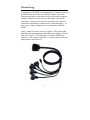
Connecting
Connecting the ES-SloMo is straightforward. Connect the large 25
pin D-Sub connector to the rear of the ES-SloMo. Secure the
connector the unit by screwing the lock screws into the connector.
Connect each deck or video server to the smaller 9 pin D-Sub
connectors. Some video servers have more than one connector,
which allow simultaneous control of the recorder and player. In
these cases, connect each port to its own connector on the ESSloMo.
Lastly, connect the unit to a source of power. This can be either
from the power mains using the provided power supply or directly
from 9-12 volts DC. The connector is a 2.1mm coaxial power
connector. The center pin is positive. A power switch on the rear
panel turns the unit on or off.
6
Initialization
The ES-SloMo configuration and TBar calibration can be reset by
holding the EJECT button while applying power to the unit. After
doing so, the display will show:
0HPRU\,QLWLDOL]HG
Then the display will show:
7%$51(('6&$/,%5$7,21
Follow the directions on the display.
029(72723
$1'35(66(17(5
029(72%27720
$1'35(66(17(5
This calibrates the TBar for optimum range. These values are
stored in nonvolatile memory and should never need to be
changed. After performing this, the unit will revert to normal
operation.
7
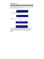
Timecode Display
When the ES-SloMo displays timecode, it displays more than just
the current timecode. The character to the left of the hours field
indicates drop frame operation. If the machine returns nondrop
frame timecode, the ES-SloMo displays a space as in the pictures
below.
7& Nondrop Timecode display in Cue and Park Mode
Nondrop Timecode display in Cue/Play/Stop
and Cue/Play/StopSlo Modes
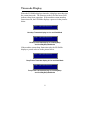
If the machine returns drop frame timecode, the ES-SloMo
displays a period or dot as in the picture below.
7& Drop Frame Timecode display in Cue and Park Mode
Drop Frame Timecode display in Cue/Play/Stop
and Cue/Play/StopSlo Modes
8
The character between the seconds and frames numbers indicates
field 1 or 2. If the machine returns field 1 in the timecode, the ESSloMo displays a period as in the pictures below.
7& Timecode display in Cue and Park Mode indicating field 1
Timecode display in Cue/Play/Stop
and Cue/Play/StopSlo Modes indicating field 1
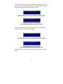
If the machine returns field 2 in the timecode, the ES-SloMo
displays a colon as in the pictures below.
7& Timecode display in Cue and Park Mode indicating field 2
Timecode display in Cue/Play/Stop
and Cue/Play/StopSlo Modes indicating field 2
Many decks do not return fields so, you may only see one or the
other.
9
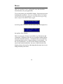
Menu
There are a number of user configurable items that should be
checked and set for your application.
To go to the menu, press the MENU button. Select the menu item
by turning the jog wheel. If you are in Shuttle Mode, the display
will tell you to go to the Jog mode. Press the wheel to go to Jog
mode, and press the MENU button again.
*RLQWR-RJ0RGH
As the Jog wheel is turned, different menu items are displayed on
!7LPH&RGH7\SH
GURS
the top line of the window.
There are two types of items accessed this way: Parameters and
Commands. Parameters allow the user to modify settings and are
stored in nonvolatile memory. Commands allow you to perform
certain operations such as a memory dump or clear memory. In
the case of parameters, you will see the currently selected and
stored value on the bottom line. An arrow of the left side of the
display points to the top line, indicating that the menu item is now
being selected by the wheel.
10
Once the desired menu item is shown, a press of the ENTER key
will cause the arrow to change to the bottom line of the display.
7LPH&RGH7\SH
!GURS
This indicates that turning the Jog wheel will scroll the possible
options for that menu item. Pressing the ENTER key again will
return the arrow to the top line, and additional menu items may be
scrolled thru. When all options have been set, another push of the
MENU button will save them to the nonvolatile memory. If you
decide to not save, pressing the CLR/ESC key will exit out of the
menu mode without saving.
When commands are reached at the end of the parameters, the
arrow symbol no longer appears. The second line will now be an
instruction, such as (17(5 (UDVH. In some cases, additional
instructions may appear after the pressing of ENTER. Pressing the
CLR/ESC key will exit out of the menu operation.
On the following pages are the list of parameters and commands
along with all the possible options. The defaults after initialization
are shown in boldface.
11
Parameters
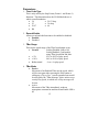
1. Time Code Type
This is only used by the Step Frame (Frame+1 and Frame-1)
functions. This determines how the ES-SloMo behaves at
whole second boundaries.
• 24
• 29.97 drop
• 25
• 30 drop
• 29.97
• 60
• 30
2. Record Enable
Allows record and edit functions to be enabled or disabled.
• Enabled
• Disabled
3. TBar Range
This sets the speed range of the TBar from bottom to top.
• Normal
Scaling Disabled: Still to 10x
Scaling Enabled: Configurable
using TBar Speed Min and Max.
• ± 5%
95% to 105% of play speed
• ± 10%
90% to 110% of play speed
• Bidirectional
-1x to +1x play speed
4. TBar Mode
• Passive
Movement of an Enabled TBar sets the speed, which
will be sent upon either pressing the Play button or
calling up a Clip or Cue. Actual command sent would
be selected by the "TBar Message" below unless set at
exactly Play speed, in which case a Play message will
be sent.
• Active
Movement of the TBar immediately sends an
appropriate command to machine when Enable LED is
on.
12
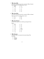
5. TBar Speed Min
This sets the minimum speed to be sent by the TBar in Normal
Mode when the T1 (Scaling) button is active
• ⅛x
• Still
1
• /64x
• 3/16x
• ¼x
• 1/32x
3
• ⅜x
• /64x
1
• /16x
• ½x
• ¾x
• 3/32x
6. TBar Speed Max
This sets the maximum speed to be sent by the TBar in Normal
Mode when the T1 (Scaling) button is active
• 1x
• 4x
• 1½x
• 8x
• 2x
• 10x
7. TBar Speed Preset
Sets the Preset Speed to be evoked by pressing the Preset
Button
• Still
• ¼x
1
• ⅜x
• /64x
1
• /32x
• ½x
• 3/64x
• ¾x
1
• /16x
• Play
3
• /32x
• 1½x
• ⅛x
• 2x
3
• /16x
• 4x
8. TBar Message
This sets the type of command sent by unit during TBar
operations
• Jog
• Variable
• Shuttle
13
9. Stop Æ TBar
This determines if pressing the STOP, PLAY, R-PLAY, REW
or FFWD button will disable the TBar and turn off ENABLE
LED.
• No Effect
• Turns Off
10. Step Frame
This determines what will happen when a Frame+1 or Frame-1
button is pushed.
• GoTo Mode
This will issue a GoTo to the proper frame. This should
be used with most "modern" machines, as it can cause
inaccurate locating with older machines such as the
BVU-800.
•
SloMo Mode
This issues a slow shuttle command in the appropriate
direction, then a Still command when the desired frame
has been reached. This does not work well with diskbased recorders.
•
Step Fwd/Rev
This sends a 2x 14 or 2x 24 command that is
recognized by only very new machines.
11. Audio Trk Type
This determines how the audio track arming is handled.
• Type 1
Older decks with 2 analog tracks.
A1 = Analog Audio 1 (This is sometimes interpreted as
Digital Audio 1 in some decks)
A2 = Analog Audio 2 (This is sometimes interpreted as
Digital Audio 2 in some decks)
Shift + A1 = Analog Audio 3 (TC in some decks)
Shift + A2 = Analog Audio 4 (Sync in some decks)
14
•
Type 2
Sends a 2 byte track arm message with the A1 & A2 bits
copied from the D1 & D2 bits. Tally back uses byte 5 of
the Status Data message.
A1 = Analog Audio 1 and Digital Audio 1
A2 = Analog Audio 2 and Digital Audio 2
Shift + A1 = Digital Audio 3
Shift + A2 = Digital Audio 4
•
Type 3
Same as Type 2, except Tally back uses the Edit Preset
Sense message.
A1 = Analog Audio 1 and Digital Audio 1
A2 = Analog Audio 2 and Digital Audio 2
Shift + A1 = Digital Audio 3
Shift + A2 = Digital Audio 4
•
Type 4
Same as Type 2, except the A1 & A2 bits are set to zero.
A1 = Digital Audio 1
A2 = Digital Audio 2
Shift + A1 = Digital Audio 3
Shift + A2 = Digital Audio 4
12. Stop Method
Sets Stop behavior.
• STOP Command
A Stop command is sent.
•
STILL Command
A Shuttle=0 (Still) command is sent.
•
2nd push STOP or STILL,STOP
The first push will cause a Still command to be sent.
The second push will cause a Stop to be sent.
15
13. FFwd and Rew
Sets Fast Forward and Rewind behavior.
• Latched
After release of the key, the controlled unit will remain
in selected operation until some other button is pressed.
•
Momentary
Upon release, either a Stop or Still will be sent,
depending on the Stop Method selected above.
14. Trk Data Tally
Allows disabling of this tally, which, under unusual
circumstances, might disrupt normal track select operations. If
this is disabled, the ES-SloMo will not "know" of any track
operation done on the controlled unit itself.
• Disabled
• Enabled
15. W1 Button Send,
W2 Button Send
Allow user selection of the command sent by the W1 and W2
buttons.
• Off (no command sent)
• Preroll
• Full EE On
• Preview
• Full EE Off
• Review
• Select EE On
• Autoedit
• ½x Play
• Sync Play
• ½x Rev Play
• Toggle Clip Enable
see "Editing the Cue List" below
• Change SloMo
see "Editing the Cue List" below
16
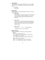
16. Show Shut Spd
Enables or disables display of the Shuttle speed in the display
window.
• Disabled
• Enabled
17. Log Operation
Enables or disables Log Operation.
(See Log Operation in appendix)
• Disabled
• Enabled
18. Cue Operation
This determines how cues are stored and played back and the
definition of a cue.
• Cue and Park
Cues are only defined a start time. When a cue is
recalled, a CueUp message is sent to unit and no further
action is taken. Cue start times are captured using the
Store Cue button. This mode allows 1000 cues.
•
Cue/Ply/Stop
Cues are stored as start and stop times. When a cue is
recalled, a CueUp message is sent. When the unit
reports that it is cued, a Play command is issued. When
the play time agrees with the stop time, a Stop
command is issued. Cues are captured using the Mark
In/Out keys, along with the ENTER key. This mode
allows 400 cues composed of start and stop times.
•
CuePlyStopSlo
Intended primarily for Sports. Like the operation above,
except that when the cue is captured, the present setting
of the TBAR is saved as a SloMo setting. This may be
done without the TBAR actually affecting the speed of
playback at the time the capture takes place. When a
cue is recalled, this SloMo speed setting will be used
17
instead of the Play command (unless the current setting
of the TBAR is at Play speed, in which case, a normal
Play command is issued). This mode allows 400 cues
composed of start and stop times with a speed value.
19. Preroll Time
Sets the amount of preroll applied to all Goto operations.
• 0 second
• 15 frames
• 1 second
• 2 seconds
• 3 seconds
• 4 seconds
• 5 seconds
• 6 seconds
• 7 seconds
• 8 seconds
• 9 seconds
20. Cue Delay Time
Sets the amount of delay between cues when in Play All Cues
operation.
• 0 to 8 seconds. (Default is 0 seconds)
21. Mach 1 Control
Enables or disables the machine on port 1. This is intended for
units that have the ability to simultaneously record and
playback. This feature allows the operator to start the recorder
at the beginning of an event and then locking out the controls
to prevent the accidental stopping of the record process.
• Disabled
• Enabled
18
22. Gangway Oper. (v1.23 or later firmware)
Enables or disables control of an optional JLCooper
Electronics Gangway16 RS-422 router. Enabling this option
repurposes the 1, 2, 3 & 4 buttons and LEDs below the T-Bar
for remote control of the Gangway16. See the section on
Gangway Operation.
19
Commands
23. Ply All Clips
This allows the automatic playback of valid and enabled cues,
starting with the currently selected one. When a blank cue is
reached, the operation ends. A blank cue is defined as a cue
with a stop time = 00:00:00:00, which is the internal condition
of erased cues. You must be in Cue/Play/Stop or CuePlyStp
Slo modes for this operation to take place! After each cue is
played, the controlled unit will stop for a period set by the Cue
Delay Time, and then proceed to the next cue.
•
ENTER
When the ENTER key is pressed to initiate this
command, a second message appears telling the
operator to place the destination deck into record,
then press ENTER again to begin.
•
W1 or W2
By selecting the W1 or W2 button to be "Tog Clip
Enable", it is possible.
•
CLR/ESC
Pressing the CLR/ESC button at any time aborts the
operation.
24. Ply Odet Clips
This the same as Play All Cues, except that it uses the Odetics
protocol to accomplish the playback. All other description of
Play All Cues is valid.
25. Xmit Cue List
Pressing the ENTER key causes all non zero cue location data
to be sent over port #4 to either another ES-SloMo unit or a
computer. When attaching to another ES-SloMo unit, a
special RS-422A crossover cable is necessary. When attaching
to a computer, as RS-422A port or RS-422A to RS-232
converter is necessary.
20
When the ES-SloMo is in Cue and Park mode, the data format
conforms to the Ash Vale SM-2a protocol. When the ESSloMo is in Cue/Ply/Stop or CuePlyStopSloMo mode, the data
format is unique to the ES-SloMo.
Both formats are detailed in the appendix.
26. Rcv Cue Dump
Pressing the ENTER key causes the ES-SloMo to prepare itself
for reception of a Cue Dump from another ES-SloMo or from a
computer. Reception is via port #4. The Es-SloMo will
automatically detect which format is being sent to it. Pressing
the CLR/ESC button aborts this operation.
When sending data from a computer, a 25 mS delay must be
inserted between each cue to allow the unit to write to
nonvolatile memory. The ES-SloMo performs this when it
sends data.
27. Erase All Cues
In Cue and Park mode, pressing the ENTER key will set all
1000 cue locations to 00:00:00:00, which is considered an
erased location.
In Cue/Ply/Stop mode, pressing the ENTER key will set all
400 start and stop times to 00:00:00:00, which is considered an
erased location.
In CuePlyStopSlo mode, pressing the ENTER key will set all
400 start and stop times to 00:00:00:00 and set the speed to 00
00, which is considered an erased location.
21
28. Init for Sports
Pressing the ENTER key will set up parameters for typical
sports slow motion operation.
•
•
•
•
•
•
•
•
•
•
•
•
•
•
•
•
•
•
•
•
•
•
Frame rate and type = 30 drop
Record Enabled
TBar = Normal range
TBar = Passive
Min TBar = Still
Max TBar = Play Speed
TBar Preset = Play Speed
TBar sends Shuttle
Stop/FF/Rew have no effect on TBar Enable
Step Frame = GoTo
Type 2 Audio track handling
Stop button sends Stop
Latched FF and Rew
Enabled Track Tally
W1 toggles Clip Enable
W2 writes new SloMo speed on current Clip
Display Shuttle Speed Off
Log Function Off
Cue operation = Cue/Play/Stop with SloMo
Preroll = 0 sec
Clip Delay = 0 sec.
Mach 1 Control = Enabled
22
29. Init for Coords
Pressing the ENTER key will set up parameters for another
typical sports slow motion operation.
•
•
•
•
•
•
•
•
•
•
•
•
•
•
•
•
•
•
•
•
•
•
Frame rate and type = 30 drop
Record Enabled
TBar = Normal range
TBar = Passive
Min TBar = Still
Max TBar = Play Speed
TBar Preset = Play Speed
TBar sends Shuttle
Stop/FF/Rew have no effect on TBar Enable
Step Frame = GoTo
Type 2 Audio track handling
Stop button sends Stop
Monentary FF and Rew
Enabled Track Tally
W1 Off
W2 Off
Display Shuttle Speed Off
Log Function Off
Cue operation = Cue and Park
Preroll = 15 frames
Clip Delay = 0 sec.
Mach 1 Control = Enabled
23
Cue Operations
There is nonvolatile storage on the ES-SloMo for 1000 cues or 400
clips. These are numbered 000 – 999 or 000 - 399. The various
operations involving cues are as follows:
Basic Cue Operations
To Goto a Predefined Cue #
1. Enter the 1,2 or 3 digit number: the time will show on line
#2 of the display, while the entry is shown on line #1.
2. Press Enter. A locate command will be issued, and the top
line will revert to showing current time.
Note: If Preroll is enabled, that will be applied to time.
3. The next action will depend upon the Cue Operation mode
that the unit is configured for.
•
•
•
If in Cue and Stop mode, the controller does nothing.
If in Cue/Ply/Stop mode, the controller will send a Play
command when Mark In point is reached (minus any
Preroll), and will send a Stop command when the Mark
Out point is reached.
If in CuePlyStopSlo mode, the controller will send a
Variable Play command when Mark In point is reached
(minus any Preroll), and will send a Stop command
when the Mark Out point is reached.
4. Pressing the CLR/ESC button will exit the cue entering
process, but will allow the entered cue to remain "pending"
for possible Cue/Ply/Stop time capture operation.
24
Next Cue
Pressing this will bring up the next higher cue from the last entered
or used. The time stored in this Cue location will be displayed on
the second line. Multiple presses of this will scroll thru the Cues.
•
Pressing Enter will cause the currently displayed Cue to
be sent.
•
Pressing the Clr/Esc button will exit back to normal
operation without sending the Cue.
Last Cue
This operates the same as above, except that the Cue number is
decremented with each push.
Current Cue
Pressing the ENTER key will replay the most recently selected
cue. This may be done repeatedly.
“Cue and Park" Specific Operations
To Manually Enter a Goto Time
1. Press ManTime button. The display will show:
(QWHU7LPH
2. Start pressing numbers: they will scroll from right to left
across screen. At any time, a first press of the CLR/ESC
button will clear whatever entry is being made to all zeros.
A second push of the button will exit the operation.
3. When the desired time is displayed, press Enter. The GoTo
command will be issued and the top line will revert to
showing current time.
Note: If Preroll enabled, that will be applied to time.
25
To store Current Time to a Cue #
1. Press StoreCue. If no manual entry of time has been made,
the Current Time will transfer to bottom line and
6725(&XH
will appear on top line.
2. Enter a 1, 2 or 3 digit number.
3. Press Enter. Current time will be stored, and display will
revert. No Goto will be sent.
To store a manually entered time to a Cue #
1. Press ManTime button. The display will show:
(QWHU7LPH
2. Start pressing numbers: they will scroll from right to left
across the screen.
3. When desired time entered, press StoreCue. The display
will show:
6725(&XH
4. Enter a 1, 2 or 3 digit number.
5. Press Enter. The entered time will be stored, and the
display will revert. No Goto will be sent.
To copy a time from one Cue to another
1. Enter a 1 or 2 digit Cue number. The associated time will
be shown on the second line.
26
2. Press StoreCue. The display will show:
6725(&XH
3. Enter a 1, 2 or 3 digit number.
4. Press Enter. The entered time will be stored, and the
display will revert. No Goto will be sent.
“Cue/Ply/Stop” and “CuePlyStp Slo” Specific
Operations
Saving a Cue with Start and Stop times
1. Insure that in either Cue/Ply/Stop or CuePlyStp Slo mode.
2. Select a starting Cue number by entering the number on the
keypad, then pressing CLR/ESC. The number will show as
the leftmost 3 digits on the top line.
3. At desired Start point, press Mark In. An asterisk appears
to the right of the cue number. This may take place with
unit playing at any speed or stopped.
4. At desired Stop point, press Mark Out. Again, this may
take place with unit playing at any speed or stopped. The
Store Cue LED will light, and the current time will freeze
on the display.
5. If planning to have the automatic SloMo speed captured,
you can at this point move the TBar to a desired speed,
which will be displayed on the second line. If the
ENABLE LED is off, this may be done without affecting
the playback that may be going on.
27
6. Press the ENTER key. The Start and Stop times, along
with the SloMo speed will be saved to the currently
displayed storage location, then the Cue number will autoincrement.
7. Repeat steps 3 thru 6. Each time, the Cue number will
increment to the next.
Playing back a Cue/Ply/Stop or CuePlyStp Slo Cue
1. Make sure in correct mode.
2. Enter the desired Cue number on the numeric keypad.
3. Press ENTER
4. Controlled unit will be directed to cue to the Start time
minus any preroll time. Once there, either a Play or a
SloMo command will be issued. The exact command sent
is the one set in the TBar Message Menu item. When the
unit has reached the prestored Stop point, a Stop command
is issued.
Editing the Cue List
It is possible to step thru the list of Cues and Enable or Disable
them individually for inclusion in the "Play all Clips" playback.
1. Set the W1 or W2 button for Toggle Clip Enable.
2. As you step thru the clips using the Next, Last, or
numerical input, the selected W1 or W2 button's LED will
light if a clip is enabled. Pressing the button toggles the
condition.
It is possible to change the SloMo speed that a CuePlyStp
Slo Clip plays back. This will take effect on individual
recalls of a Clip or on the Play all Clips" operation.
28
3. Program the W1 or W2 button for "Change SloMo"
operations.
4. With the TBar Enabled, recall a Clip.
5. Move the TBar to a desired speed (optional at this point).
6. Recall a clip. While playing, you may move the TBar to
desired speed.
7. When set to desired speed, press the W1 or W2 button
programmed in step 3 above. The new speed will now be
written to the current clip.
29
TBar Operation
The TBar may be set via "TBar Range" to Normal, ±5%, ±10%, or
bidirectional operation.
Normal
There are three main aspects of the "Normal" speed operation of
the TBar, as follows:
Full Range Operation
Press the ENABLE button. As soon as the TBar is moved, a
speed command (depending on message choice made in the
Menu) will be sent. The range of operation is from Still (all the
way toward the operator) to 10x normal play speed.
A subsequent press of the ENABLE button will turn the TBar
off. Depending on selection within the Menu, the pressing of
any "transport" button (REW, R-PLAY, STOP, PLAY, FFWD)
may be made to turn the TBar off.
Scaled Range Operation
Press the T1 button. The TBar will be enabled. The Minimum
speed of the T Bar will now be the value set in the Menu Item
TBar Speed Min. The Maximum speed will now be the value set
in the Menu Item TBar Speed Max.
Preset Operation
It might be desired to be able to always start T Bar operation at
a know speed different from the Max or Min value. When the
PRESET button is pushed, a speed value equal to the speed set
in the Menu Item "TBar Speed Preset" will be immediately
sent. That speed will be shown on the second line of the
display. Unless the TBar happens to be sitting at the Preset
speed, the PRESET LED will blink indicating that the T Bar
needs to be moved to the "null" point (the point where the T
Bar position is the same as the Preset).
30
On the far right of the display, an up or down arrow will show
which direction the T Bar needs to be moved. When the TBar
is moved past the Preset point, the LED will turn off, and the
arrow will disappear. The T Bar is now "Live".
When the ENABLE LED is off, movement of the T Bar will
display (for about 1/2 second) the speed that would be sent
were the T Bar enabled. This includes any min/max scaling if
the T1 LED is lit. By this means, the operator can go to an
exact speed position at any time without causing the controlled
machine to move.
±5% Play Range
With this range, the Preset and Range buttons do nothing. The
range of the TBar is from about 95% of normal play speed to about
105%.
±10% Play Range
With this range, the Preset and Range buttons do nothing. The
range of the TBar is from about 90% of normal play speed to about
110%.
Bidirectional
With this range, the Preset and Range buttons do nothing. The
range of the TBar is from 100% reverse play speed to 100%
forward play speed.
31
Edit Preset (Track Arming)
The ES-SloMo includes buttons dedicated to adjusting the Edit
Preset status of a target machine. The main modes are:
Crash Recording
Insure that neither the INS nor ASM LEDs are on. Holding
down the Shift button, then pushing the PLAY button will
place the machine(s) in the Crash Record mode.
Assemble Recording
Toggle the ASM button so that it is on. Holding down the
Rec/Shift button, then pushing the PLAY button will place the
machine(s) in the Assemble Record (Edit) mode.
Insert Recording
Toggle the Ins button so that it is on. In addition, press the
desired tracks so that they are on. Immediately available are
the Video, A1 and A2 tracks. When the Rec/Shift is pushed,
the A1 and A2 buttons/LEDs become the D3 and D4 toggles.
Holding down the Rec/Shift button, then pushing the PLAY
button will place the machine(s) into the Insert Record (Edit)
mode. If no Video or Audio track is enabled, only the Play
command will be sent.
To exit any of the modes while the deck in motion, simply press
the Stop button.
The exact command sent will depend on the $XG7UN7\SHmenu
item.
32
Machine Control
Any combination of four machines may be controlled by the ESSloMo. The four buttons labeled "Machine Control" indicate and
modify the machines that will receive commands. Pressing a single
button will switch both the output of the ES-SloMo and the tally
back to it to the selected machine. If more than one button are held
down, all units will receive commands from the ES-SloMo. In
this case, the first one pushed will become the machine used for
Tally operations (current time code, transport control LEDs, and
Edit Presets.) In a multi-machine operation, the selection of tally
machine made during the output select process may be overridden
by holding down the Rec/Shift button, then selecting a machine.
As soon as the Rec/Shift button is held, the current tally machine
will be displayed.
Upon power-up, the unit will always start with machine #1
selected unless the menu item Mach 1 Control is set to Disabled.
In that case, the ES-SloMo will start up with machine #2 selected.
33
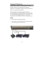
Gangway16 Operation
When Gangway16 Operation is enabled in the menu, the ESSloMo is able to remotely control the Gangway16. The ES-SloMo
must have version 1.23 or later firmware to control the
Gangway16. The Gangway16 requires version 1.01 firmware or
later to be controlled by the ES-SloMo.
Firmware upgrades are available for purchase from the
JLCooper Electronics Service Department. You can contact the
Service Department by dialing (310) 322-9990 in North America
or +1-310-322-9990 outside North America. The Service
Department is also available by email at: [email protected].
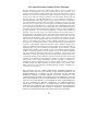
Setup
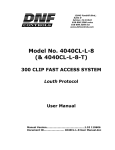
To use the Gangway16 with the ES-SloMo:
1. Connect port 1 of the ES-SloMo to the rear panel controller
port of the Gangway16 as shown below.
34
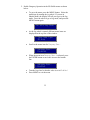
2. Enable Gangway Operation in the ES-SloMo menu as shown
below.
•
To go to the menu, press the MENU button. Select the
menu item by turning the jog wheel. If you are in
Shuttle Mode, the display will tell you to go to the Jog
mode. Press the wheel to go to Jog mode, and press the
MENU button again.
*RLQWR-RJ0RGH
•
As the Jog wheel is turned, different menu items are
displayed on the top line of the window.
!7LPH&RGH7\SH
GURS
•
Scroll to the menu item for *DQJZD\2SHU
!*DQJZD\2SHU
'LVDEOHG
•
When the menu item *DQJZD\2SHU is selected, press
the ENTER button to move the cursor to the bottom
line.
*DQJZD\2SHU
!(QDEOHG
•
•
Turn the Jog wheel so that the value is set to (QDEOHG.
Press MENU to exit the menu.
35
Gangway16 Controls
When Gangway Operation is enabled in the menu, the Machine
Control buttons and LEDs are repurposed to control the
Gangway16. In this case, the functions of the buttons and LEDs
are as follows:
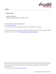
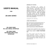
Labeling
Since the default labeling of these 4 buttons is for the Machine
Control function, a plastic decal (shown below) is supplied with
the unit which allows the labeling of the buttons with the Gangway
functions. If desired, this decal can be applied the ES-SloMo
above the four Machine Control as shown above to clarify the
operation of these buttons and LEDs.
36
Enable
Pressing this button enters the Gangway16 configuration mode. In
this mode, the Enable LED will illuminate and the VFD will show
the Gangway16 routing.
All On
When this button is pressed, the Gangway is configured to enable
all 16 ports.
All Off
When this button is pressed, the Gangway is configured to disable
all 16 ports.
Tally
Pressing this button allows you to select the port, which provides
Tally information (timecode, status) to the ES-SloMo. In this
mode, the Tally LED will illuminate and the VFD will show the
Gangway16 Tally routing.
37
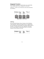
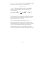
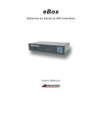
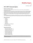
Controlling the Gangway16
To control the Gangway16, simply press the Enable button. The
Enable LED will illuminate and the display will show similar to
the screen shot below.
s
← Port 1
← Port 2
← Port 3
← Port 4
← Port 5
← Port 6
← Port 7
← Port 8
← Port 9
← Port 10
← Port 11
← Port 12
← Port 13
← Port 14
← Port 15
← Port 16
The top line indicates the ports of the Gangway16, = Port 1, =
Port 2 and so on. Starting with , only the last digit is shown due
to space constraints. In this case, = Port 10, = Port 11 and so
on.
s
The bottom line indicates which ports are enabled. The presence
of an arrow pointing up indicates that a port is enabled for output.
While the absence of an arrow indicates that the port is not enabled
for output.
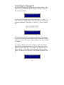
To enable or disable a port on the Gangway, make sure that the
Enabled LED is illuminated then, key in the 2 digit entry on the
numeric keypad for the port. For example, to toggle the state of
Port 6, press 0, 6. The display will be similar to the screen shot
below. In addition, the Gangway16 will illuminate buttons 1 and
6.
ss
38
This indicates that Ports 1 and 6 are enabled for output that is,
commands from the ES-SloMo will be sent to decks connected to
Ports 1 & 6.
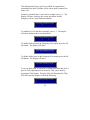
Similarly, to disable Port 1 in the above example, press 0, 1. The
display will show similar to the screen shot below and the
Gangway will now only illuminate button6.
s
To enable Port 12 in the above example, press 1, 2. The display
will show similar to the screen shot below.
ss
To enable all the ports on the Gangway16 for output, press the All
On button. The display will show:
ssssssssssssssss
To disable all the ports on the Gangway16 for output, press the All
Off button. The display will show:
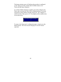
To receive data (such as Timecode or Status) back from the deck, a
port for Tally operation must be selected. This can be done by
pressing the Tally button. Pressing Tally will illuminate the Tally
LED and cause the display to show the following:
r
39
The down pointing arrow will indicate the port that is configured
as the Tally port or the port that the ES-SloMo listens to for
Timecode and Status responses.
As with the Enable function, to enable a port on the Gangway for
Tally, make sure that the Tally LED is illuminated then, key in the
2 digit entry on the numeric keypad for the port. For example, to
select Port 9 for Tally, press 0, 9. The display will be similar to the
screen shot below.
r
To remove the Gangway16 configuration pages, simply press the
Enable button. This will cause the display to revert to normal
operation.
40
Appendix
Log Operation
When doing QC work with films or tapes, an operator must look
for flaws, and log the type of flaw and time code, often by hand.
The ES-SloMo includes a mode to help automate this task. When
in this mode (accessed thru the Menu Item "Log Operation",)
Machine #4's output is used to send a special command upon the
operator's pushing of one of the buttons immediately below the
display. This command will be in the form:
74h bb ff mm ss hh cs
where:
bb is button # from 0 to 5. This is intended to be an indication
of the type of flaw found by the operator and is entirely
definable by the user.
ff mm ss hh is the timecode as returned from the machine
immediately preceding the button press. It is in BCD format.
cs is checksum of all the bytes in the packet preceding it. The
checksum is truncated to the least significant 8 bits.
The data transmission from the ES-SloMo follows the standard P2
specification. EIA RS-422A at 38400 bits/sec, 8 data bits, 1 stop
bit and odd parity. The user will need to (usually) provide a RS422 to RS-232 or USB converter, and will need to provide a simple
application that receives this data and presents it in a useful format.
JLCooper may provide this software at some point in the future,
depending on demand. Contact the factory for details.
For details on how to connect your ES-SloMo to a computer, refer
to the pinout section.
41
Clip Transfer Protocol
The ES-SloMo can transfer cue information in one of two
protocols:
•
•
Ash Vale SM-2a
ES-SloMo
The SM-2a protocol is:
The port settings are:
38400 bits/sec, no parity, 8 data bits, 1 stop bit.
The data format is
0Dh 0Ah <Cue#> 20h <Time>
:
0Dh 0Ah <Cue#> 20h <Time>
0Dh 0Ah @
The ES-SloMo protocol is:
The port settings are:
38400 bits/sec, no parity, 8 data bits, 1 stop bit.
The data format is
0Dh 0Dh 0Ah <Cue#> 20h <StartTime> 20h <EndTime>
20h <n1> <n0>
:
0Dh 0Dh 0Ah <Cue#> 20h <StartTime> 20h <EndTime>
20h <n1> <n0>
0Dh 0Dh 0Ah @
Cue# is a 3 digit ASCII value (000 to 999 or 000 to 399) that
specifies the cue location.
42
Time, StartTime and EndTime are 11 digit ASCII values
that specifies timecode values in the following format:
hh:mm:ss:ff
n1 and n0 define play speed for the clip in CuePlyStop Slo
mode. The actual play speed is can be determined by the
following equation.
TapeSpeed = 10
n1
−2
32
n1 +1
n1
−2
−2
n0 32
+
× 10
− 10 32
256
These are the same values sent from the ES-SloMo to a machine
and are defined on page 17 of the Sony document Protocol of
Remote (9-pin) Connector 2nd Edition.
The ‘@’ character terminates the sending of cue data.
When sending data from a computer, a 30 mS delay must be
inserted between each cue to allow the unit to write to nonvolatile
memory. The ES-SloMo performs this when it sends data.
For details on how to connect two ES-SloMos together or to
connect your ES-SloMo to a computer, refer to the pinout section.
43
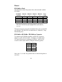
Pinout
ES-SloMo to Deck
The table below details the pinout of the cable included with the
ES-SloMo.
ES-SloMo
Function
Ground
Receive A
Transmit B
Receive B
Transmit A
Machine
1
21
22
10
9
23
Machine
2
11
25
12
13
24
Machine
3
16
17
5
4
18
Machine
4
6
20
7
8
19
Ports
1,2,3,4
1
2
3
7
8
Note: Some decks do not use pin 1 for ground so you may have to
connect pin 1 at each end of the ES-SloMo cable to pins 4 and 6 on
your deck.
The data transmission from the ES-SloMo follows the standard P2
specification. EIA RS-422A at 38400 bits/sec, 8 data bits, 1 stop
bit and odd parity.
ES-SloMo to ES-SloMo / ES-SloMo to Computer
To connect two ES-SloMos together, an RS-422A crossover
adapter or cable will be needed. An adapter is available from
JLCooper Electronics by ordering p/n 620026. An RS-422A
crossover cable can be made by using the following pinout:
1,4,6&9 1,4,6&9
2
8
3
7
7
3
8
2
Note: pins 1, 4, 6 and 9 are grounds and are connected together at
each end.
44
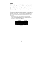
Power
The ES-SloMo requires a 9-12 volt DC power supply capable of
delivering 500 milliamps or more. This can be either from the
power mains using the provided power supply or directly from 912 volts DC. The connector is a 2.1mm coaxial power connector.
The center pin is positive. A power switch on the rear panel turns
the unit on or off.
The unit comes with a power supply appropriate for the country in
which the unit was sold. If you need a power supply specific to
your location, please contact your local distributor or JLCooper
Electronics.
Warning: Using a power supply other than the unit specified could
result in damage to the ES-SloMo and/or other equipment, which is not
covered by the JLCooper Factory Warranty.
Location
North America
Europe (except UK)
Japan
JLC P/N
PSDC117
PSDC230
PSDC117
JLCooper Approved Power
Supplies
45
Troubleshooting
If for some reason the ES-SloMo does not give you the expected
results, take a moment to do some investigating. The most
important concept is that you have your ES-SloMo connected
properly as outlined in Installation and Use. Take a moment to
double check your setup.
A common problem is forgetting to turn the power switch on or
turning the unit on after the software application has launched.
In addition, the JLCooper website (www.jlcooper.com) will
contain up to date information on drivers, applications and
troubleshooting.
If all else fails, you can contact the JLCooper Service Department
at: [email protected].
Care and Service
If properly cared for, your ES-SloMo should provide years of
troublefree performance. While the ES-SloMo is built in a rugged
metal enclosure, please avoid dropping the ES-SloMo.
Clean with a soft, damp cloth. Do not allow liquids, dust or other
foreign matter to get inside the unit.
There are no user-serviceable parts in the ES-SloMo. Please refer
to the JLCooper Electronics Limited Factory Warranty on the
following page for detailed warranty and service information.
46
JLCooper Electronics Limited Factory Warranty
JLCooper Electronics ("JLCooper") warrants this product to be free of defects in
materials or workmanship for a period of 12 months from the date of purchase. This
warranty is non-transferable and the benefits apply only to the original owner. Proof of
purchase in the form of an itemized sales receipt is required for warranty coverage. To
receive service under this warranty, customers in the United States should contact the
JLCooper factory at (310) 322-9990 and talk to a service technician. If necessary, a
Return Authorization number may be issued. For our customers outside the United States,
it is recommended that you first contact your Dealer or Distributor, since they may offer
their own service or support policy. If local support is not obtainable, please send a FAX
to JLCooper's Service Department at +1 310 335 0110 with a detailed description of the
service required. Upon issuance of return authorization, the product should be packed in
the original shipping materials and shipped prepaid and insured to: Service Department,
JLCooper Electronics, 142 Arena Street, El Segundo, CA 90245. Please include the
following: copy of the sales receipt, your name and address (no P.O. Boxes, please), a
brief description of the problem, and any other related items discussed with the service
department and considered necessary to evaluate the product or effect a repair. The return
authorization number must be clearly written on the outside of the package. JLCooper
will, at its option, without charge for parts or labor, either repair or replace the defective
part(s) or unit. Shipping costs, duties, customs, brokerage and other fees to and from
JLCooper are not covered by this warranty. JLCooper's normal repair turn around time at
the factory is approximately 10 business days from receipt of product to shipping. Your
actual turn around time will include return shipping. Actual turn around time will vary
depending upon many factors including the repeatability of the customer's reported
complaint, the availability of parts required for repair, the availability of related products
needed to evaluate the product if necessary. Priority services are available at additional
cost. These should be discussed with the service representative at the time the return
authorization is issued. This warranty provides only the benefits specified and does not
cover damage, defects or repairs needed as result of acts beyond the control of JLCooper
including but not limited to: abuse, damage by accident or negligence, damage from
using incorrect power supply, modification, alteration, improper or abnormal use,
unauthorized servicing, tampering, ingress of foreign matter or failure to operate in
accordance with the procedures outlined in the owner's manual; nor for natural or manmade events such as, but not limited to flooding, lightning, tornadoes, earthquake, fire,
civil unrest, war, terrorism, etc.
THE DURATION OF ANY OTHER WARRANTIES, WHETHER IMPLIED OR
EXPRESS, INCLUDING BUT NOT LIMITED TO THE IMPLIED WARRANTY OF
MERCHANTABILITY, IS LIMITED TO THE DURATION OF THE EXPRESS
WARRANTY HEREIN. JLCOOPER HEREBY EXCLUDES INCIDENTAL AND
CONSEQUENTIAL DAMAGES, INCLUDING BUT NOT LIMITED TO: LOSS OF
TIME, INCONVENIENCE, DELAY IN PERFORMANCE OF THIS WARRANTY, THE
LOSS OF USE OF THE PRODUCT OR COMMERCIAL LOSS, AND FOR BREACH
OF ANY EXPRESS OR IMPLIED WARRANTY OF MERCHANTABILITY
APPLICABLE TO THIS PRODUCT. JLCOOPER SHALL NOT BE LIABLE FOR
DAMAGES OR LOSS RESULTING FROM THE NEGLIGENT OR INTENTIONAL
ACTS OF THE SHIPPER OR HIS CONTRACT AFFILIATES. THIS WARRANTY
SHALL BE GOVERENED BY THE LAWS OF THE STATE OF CALIFORNIA.
47