1
Micriµm
Empowering Embedded Systems
µC/OS-II
µC/LCD
µC/Probe
and
The Freescale MC9S12DG256
(Using the Wytec Dragon12-Plus Evaluation Board)
Application Note
AN-1456
www.Micrium.com
Micriµm
µC/OS-II, µC/LCD and µC/Probe
for the Freescale MC9S12DG256
Table Of Contents
1.00
Introduction
1.01
Source code access
1.02
Quick Start Guide
1.03
Hardware Configuration
1.04
Port Specific Details
1.05
μC/Probe
1.06
Directories and Files
1.07
Codewarrior IDE
2.00
Example Code
2.01
Example Code, app.c
2.02
Example Code, app_cfg.h
2.03
Example Code, includes.h
2.04
Example Code, os_cfg.h
3.00
Board Support Package (BSP)
3.02
Board Support Package, bsp*.*
3.03
Configuring the PLL
3.04
Vectors.c
3.05
Creating Interrupt Service Routines
4.00
Porting to Other MC9S12 Derivatives
4.01
Additional Reading
Licensing
References
Contacts
3
4
4
6
6
7
9
14
17
17
23
23
23
24
24
30
32
33
35
36
36
37
37
2
Micriµm
µC/OS-II, µC/LCD and µC/Probe
for the Freescale MC9S12DG256
1.00
Introduction
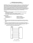
This document shows example code for using µC/OS-II, µC/LCD and µC/Probe on a
Freescale MC9S12DG256 processor. To demonstrate the MC9S12DG256, we used a Wytec
Dragon12-Plus Evaluation Board as shown in Figure 1-1.
We used the Freescale Codewarrior IDE version 4.5 and Freescale Serial Monitor to compile and
load this application. However, other tool-chains may be used.
Figure 1-1, Wytec Dragon12-Plus Evaluation Board
The application code is downloaded into flash memory using the Freescale serial monitor
application. The serial monitor has been preinstalled within the MC9S12 flash memory prior to
shipping from Wytec. In order to download the demonstration application to the MC9S12, the
host PC must have an available serial port. If a serial port is unavailable, it is possible to
download and debug the application using a P&E Multilink BDM and changing the project
configuration settings found above the build tree from ‘HCS12 Serial Monitor’ to ‘P&E Multilink
Cyclone Pro’.
Once the application has been loaded into the MCU flash memory, the user may either run the
application from the debugger or switch the EVB to RUN mode and press reset. Once the
application is running, the onboard LCD and seven segment displays will update. After a few
seconds, the user will be prompted via the LCD that the keypad is available for use. Keys
pressed during this time will be displayed on the bottom row of the LCD.
3
Micriµm
µC/OS-II, µC/LCD and µC/Probe
for the Freescale MC9S12DG256
1.01
Source code access
This application note describes a demonstration application using µC/OS-II, µC/LCD, and
µC/Probe and is based on µC/OS-II Version 2.86.
Micrium's policy in regards to getting access to source code is as follows:
µC/OS and µC/OS-II source and object code can be used by accredited Colleges and
Universities without requiring a license, as long as there is no commercial application
involved. In other words, no licensing is required if µC/OS and µC/OS-II is used for
educational use.
You need to obtain an 'Object Code Distribution License' to embed µC/OS or µC/OS-II in
a product that is sold with the intent to make a profit or if the product is not used for
education or 'peaceful' research.
You also need to obtain a 'Source Code Distribution License' to distribute µC/OS or
µC/OS-II in source code form.
For all the µC/ products other than µC/OS-II, you need to obtain an 'Object Code Distribution
License' to get access to the source code.
1.02
Quick Start Guide
Prerequisites:
1. Codewarrior 4.5 or better. A valid license file must be present. The standard
demonstration Codewarrior license is limited to 32 files and will not be sufficient for
compiling the provided application. If you do not have a full featured license and belong
to an academic institution, one may be obtained by contacting Freescale support.
2. Dragon12-Plus EVB.
3. Available serial port on the host computer. A standard UART is required by Codewarrior
when using the ‘serial monitor’ configuration to connect to MC9S12 MCU. The cable
should be connected between the host PC and SCI0 on the Dragon12-Plus.
Instructions:
1. Unzip AN1456 to c:\. This will result in the c:\Micrium\ directory being created. It is
recommended that you unzip to the default directory since it adheres to AN2002,
‘Directory Structure’ and makes supporting applications easier. It also provides for a
consistent directory structure with regards to version controlling several projects that
share the same base code.
2. Open the project file using Codewarrior version 4.5 or better. The project file is
located in the following directory and is named OS-Probe-LCD.mcp.
4
Micriµm
µC/OS-II, µC/LCD and µC/Probe
for the Freescale MC9S12DG256
\Micrium\Software\EvalBoards\Freescale\MC9S12DG256B\Wytec\Dragon12\Metrowerks\
Page \OS-Probe-LCD
3. Ensure that the Dragon12-Plus ‘Run/Load’ switch is in the ‘LOAD’ position. This may
be accomplished by switching the left hand switch of SW7 to the ‘down’ position.
4. Ensure that the current build configuration is set for ‘HCS12 Serial Monitor’. This can
be verified by viewing the pull-down box above the source code tree illustrated in the
screen shot below.
5. Build and load the application by clicking on the green debug button illustrated by the
red arrow.
6. Once the application has been loaded, there are two options.
a. Press the green arrow within the debugger to launch the application in debug
mode.
b. Change the left SW7 to the up position, ‘RUN’ mode, close the debugger and
reset the target. This will cause the application to run in stand-alone mode.
7. Additionally, you may visit the Micrium web site, www.micrium.com, and download
the latest trial version of µC/Probe. µC/Probe allows global variables to be
graphically mapped via a Windows application to various counters, gauges,
spreadsheets, switches and knobs for both viewing and changing during run-time. If
µC/Probe is utilized, a second serial cable will need to be attached between the PC
and SCI1 of the Dragon12-Plus EVB. See the section labeled µC/Probe for more
information.
5
Micriµm
µC/OS-II, µC/LCD and µC/Probe
for the Freescale MC9S12DG256
8. Once the application is running, the LCD and seven segment displays should update.
After a short while, the application will prompt the user via the LCD screen indicating
that keypad entry is now possible.
1.03
Hardware Configuration
1. Enable seven segment LED blocks by placing J24A and removing J24B.
2. Enable SCI1 for RS232 communication by setting J23 to position 2, the SCI1 setting.
3. Set the left switch of SW7 to the down position to enable LOAD mode. Once the
application is running and debugging is no longer necessary, the user may move the left
SW7 switch to the up position to enable RUN mode. From this mode, the MCU / serial
monitor will automatically start the user application upon power up.
Pins in use:
1.
2.
3.
4.
1.04
Port A, on-board keypad.
Port B, seven segment LED blocks.
Port K, character LCD.
PS0 through PS3. SCI0 for the serial monitor and SCI1 for µC/Probe.
Port Specific Details
This µC/OS-II processor port has been designed to operate in the MC9S12 banked memory
model. Paging must not be enabled within the Codewarrior project options since the PPAGE
register save and restore functionality has been included in the µC/OS-II port.
Additionally, this µC/OS-II port has been customized to work in conjunction with the Freescale
serial monitor application. As a result, this port will NOT work when the MCU is in expanded
mode since the ability to use SWI to perform context switches has been replaced with the JSR,
opposed to the CALL instruction. Applications that are loaded and run without the serial monitor
are encouraged to use the non serial monitor compliant port as it offers slightly improved context
switch performance via SWI.
This application assumes the presence of an 8MHz crystal on the Dragon12-Plus EVB. Once the
application has been initialized, the on-chip PLL is configured to 48MHz which results in a
24MHz. bus clock. The PLL settings may be changed from within bsp.h. Refer to the section
labeled “Configuring the PLL” for more information.
Next, µC/OS-II requires the use of an ECT channel for periodic time keeping. This application
configures ECT channel 7 for the µC/OS-II Ticker, however, if TC7 is not available, you may
configure an alternate ECT timer channel by adjusting the macro named “OS_TICK_OC” within
bsp.h accordingly. If the ECT channel is changed, then the file vectors.c will also require
modification. See the section labeled “vectors.c” for more information.
Lastly, all ISRs must be written as specified within the section labeled “Creating Interrupt Service
Routines”. Creating ISRs from ‘C’ without the proper µC/OS-II primitives will cause task
scheduling jitter which could result in poor real-time performance for some applications.
6
Micriµm
µC/OS-II, µC/LCD and µC/Probe
for the Freescale MC9S12DG256
1.05
μC/Probe
µC/Probe is a Microsoft Windows program that displays the content of system variables on
various user definable graphical elements such as simulated mechanical counters, graphs,
on-screen LEDs and so on.
In order for µC/Probe to display information about your application, an ELF file, must be
generated by the user’s compiler. The ELF file contains the names and addresses of all the
global symbols referenced within the users embedded application. Only symbols that have been
allocated memory, e.g. not allocated on the stack, are able to be monitored by µC/Probe. Global
and static variables are examples of variables that may be monitored.
The user places components (such as gauges, labels, and charts) into a Data Screen in a
µC/Probe workspace. Each one of these controls is then assigned to one or more of the
variables from the Symbol Browser. The Symbol Browser lists all symbols referenced from within
the ELF file. Symbols associated with components placed on an open Data Screen will be
updated after the user presses the start button (assuming the user’s PC is connected to the
target and the target is running).
µC/Probe currently interfaces with a target processor via JTAG, RS-232, UDP and USB. A
small section of code resident on the target receives commands from the Windows application
and responds to those commands. The commands ask for a certain number of bytes located at a
certain address, for example, “Send 16 bytes beginning at 0x0040102C”. The Windows
application, upon receiving the response, updates the appropriate component(s) on the data
screen(s) with the new values.
7
Micriµm
µC/OS-II, µC/LCD and µC/Probe
for the Freescale MC9S12DG256
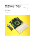
Start / Stop button.
This button switches
between Design and
Run-Time Views.
During Run-Time View
(when data is
collected), this will
appear as a stop
button (a blue square).
Symbol Browser.
Contains all symbols from the
ELF files added to the
workspace.
Data Screen.
Components are placed onto the data screen and
assigned symbols during Design View. During
Run-Time View, these components are updated
with values of those symbols from the target
Figure 2-1. µC/Probe Windows Program
To use µC/Probe with the example project (or your application), do the following:
1. Download and Install µC/Probe. A trial version of µC/Probe can be downloaded
from the Micriµm website at
http://www.micrium.com/products/probe/probe.html
2. Open µC/Probe. After downloading and installing this program, open the example
µC/Probe workspace for µC/OS-II, named OS-Probe.wsp, which should be located in
the AN-1456 Codewarrior project directory.
You may also open one of the sample workspaces that come with µC/Probe. The
sample workspace files are located in the µC/Probe target directory.
3. Connect Target to PC. Currently, µC/Probe can use RS-232 to retrieve information
from the target. You should connect a RS-232 cable between your target and computer.
Load Your ELF File. The example projects included with this application note are
already configured to output an ELF file. (If you are using your own project, please refer
to Appendix A of the µC/Probe user manual for directions for generating an ELF file with
8
Micriµm
µC/OS-II, µC/LCD and µC/Probe
for the Freescale MC9S12DG256
your compiler.) Codewarrior generates an ELF file with an .abs extension. This file is
located in a directory named BIN within the sample project directory.
To load this ELF file, right-click on the symbol browser and choose “Add Symbols”.
Navigate to the file directory, select the file, and choose “OK”.
4. Configure the RS-232 Options. In µC/Probe, choose the “Options” menu item on the
“Tools” menu. A dialog box as shown in Figure 6-2 (left) should appear. Choose the
“RS-232” radio button. Next, select the “RS-232” item in the options tree, and choose the
appropriate COM port and baud rate. The baud rate for the project accompanying this
application note is 115,200.
5. Start Running. You should now be ready to run µC/Probe. Just press the run button
to see the variables in the open data screens update.
1.06
Directories and Files
The code and documentation of the port are placed in a directory structure according to
“AN-2002, µC/OS-II Directory Structure”. Files for the banked serial monitor and non serial
monitor compliant ports have been supplied by Micrium. Specifically, the files are placed in the
following directories:
µC/OS-II:
\Micrium\Software\uCOS-II\Source
This directory contains the processor independent code for µC/OS-II. The version used
was 2.86.
\Micrium\Software\uCOS-II\Ports\HCS12\Paged\Metrowerks
\Micrium\Software\uCOS-II\Ports\HCS12\Paged\Metrowerks\SerialMonitor
These directories contain the standard processor specific files for a µC/OS-II port
assuming the Freescale Codewarrior IDE. These files could easily be modified to work
with other tool chains; however, you would place the modified files in a different directory.
Only one processor port, non serial monitor compliant or serial monitor compliant may be
compiled in to a µC/OS-II project at any given time. When switching ports, it is
necessary to remove the old port files from the build tree, add the new port files, and
adjust the access path settings to ensure that Codewarrior does not observe header files
from the old port directory.
Specifically, the required files are:
os_cpu.h
os_cpu_a.s
os_cpu_c.c
µC/Probe:
9
Micriµm
µC/OS-II, µC/LCD and µC/Probe
for the Freescale MC9S12DG256
C:\Micrium\Software\uC-Probe\Target\Communication\Generic\OS\uCOS-II
This directory contains the OS dependent interface for the communication layer of
µC/Probe. If you plan to run µC/Probe with a different RTOS, or without any RTOS,
the following files would have to be adjusted accordingly:
probe_com_os.c
C:\Micrium\Software\uC-Probe\Target\Communication\Generic\RS-232\OS\uCOS-II
This directory contains OS dependent interface code for the RS-232 specific portion of
µC/Probe, specifically the code necessary to generate an optional Rx packet parse
task. If you plan to run µC/Probe with a different RTOS, modifications to the files listed
below will have to be made. If you are not running an RTOS, the following files may be
excluded from the build.
probe_rs232_os.c
C:\Micrium\Software\uC-Probe\Target\Communication\Generic\RS-232\Ports\Freescale\MC9S12
This directory contains the µC/Probe hardware port files for the MC9S12 processor.
probe_rs232c.c
probe_rs232c.h
probe_rs232_ba.s
C:\Micrium\Software\uC-Probe\Target\Communication\Generic\RS-232\Source
This directory contains target independent source code for the µC/Probe RS-232
communication layer. Specifically, this directory contains the following files:
probe_rs232.c
probe_rs232.h
C:\Micrium\Software\uC-Probe\Target\Communication\Generic\Source
This directory contains target independent source code for the
communication layer. Specifically, this directory contains the following files:
µC/Probe
probe_com.c
probe_com.h
C:\Micrium\Software\uC-Probe\Target\Plugins\uCOS-II
This directory contains the target independent source code for µC/Probe. Specifically,
this directory contains the following files:
os_probe.c
os_probe.h
Application Code:
10
Micriµm
µC/OS-II, µC/LCD and µC/Probe
for the Freescale MC9S12DG256
\Micrium\Software\EvalBoards\Freescale\MC9S12DG256B\Wytec\Dragon12\Metrowerks\Paged
\OS-Probe-LCD
This directory contains the Freescale Codewarrior project file for the AN-1456.
OS-Probe-LCD.mcp
\Micrium\Software\EvalBoards\Freescale\MC9S12DG256B\Wytec\Dragon12\Metrowerks\Paged
\OS-Probe-LCD\Source
This directory contains the source code for an example running on the Dragon12-Plus
evaluation board. It assumes the presence of µC/OS-II.
This directory contains:
app.c
app_cfg.h
app_hooks.c
app_probe.c
datapage.c
includes.h
os_cfg.h
probe_com_cfg.h
Start12.c
vectors.c
app.c contains the application entry point, main() and example code.
app_cfg.h contains application specific configuration information such as task priorities
and stack sizes. It is highly recommended that users continue to use the app_cfg.h for all
application configuration constants instead of placing defines within several different files.
App_hooks.c contains application software hooks for many OS functions such as context
switching and idle task iterations. µC/Probe makes use of the µC/OS-II hooks in order
to use idle processor time for making various measurements.
App_probe.c contains initialization code for µC/Probe.
Includes.h is a master include file used by the application. It is recommended, but not
necessary that users include additional files from includes.h.
os_cfg.h is the µC/OS-II configuration file. Unused features of the operating system may
be disabled from within this file in order to reduce the ROM and RAM footprint of the OS.
By default, all features are enabled and the OS ticker is configured to run 1000 times per
second. This equates to a timer resolution of 1 millisecond.
Probe_com_cfg.h is a configuration file for µC/Probe. By default, µC/Probe has been
configured for task priority 9, a stack size of 160 bytes, a receive buffer of 64 bytes, and
configured to use SCI1. Any of these configuration values, including SCI selection, may
be changed if necessary.
Datapage.c and start12.c are provided by Codewarrior but have been placed in
the application directory for code warrior project consistency purposes.
11
Micriµm
µC/OS-II, µC/LCD and µC/Probe
for the Freescale MC9S12DG256
\Micrium\Software\EvalBoards\Freescale\MC9S12DG256B\Wytec ragon12\Metrowerks\Paged\BSP
This directory contains the Board Support Package for the Dragon12-Plus evaluation
board. Some of the code in this directory may work on other MC9S12 derivatives,
however, routines that are hardware dependent such as LED_On() will require
modification depending on the hardware design of the EVB.
Please see the section labeled “Board Support Package” and “Porting to Other MC9S12
Derivatives” for more information related to the BSP.
This directory contains:
bsp.c
bsp.h
keypad.c
keypad.h
sevenSegDisp.c
sevenSegDisp_OS.c
sevenSegment.s
sevenSegDisp.h
nvm.c
nvm.h
Vectors.c
bsp.c contains hardware specific source code for LED services, PLL initialization,
µC/OS-II ticker initialization, µC/LCD hardware access routines, µC/Probe timer
routines, and general purpose functions for obtaining clock frequencies during run-time.
It is highly recommended that utilize the BSP functionality and not hardcode clock
dividers during build time.
bsp.h contains macros for configuring the system PLL and µC/OS-II time tick ECT
channel. Please see the section labeled “Porting to Other MC9S12 Derivatives” for more
information related to the bsp.h.
nvm.c and nvm.h contain hardware access functions for reading and writing both Flash
and EEPROM during run-time. Neither of these files are used within the example but
have been provided for convenience. Special care should be taken when modifying the
contents of Flash or EEPROM during run-time as it may be possible to overwrite portions
of the application accidentally.
vectors.c contains the processor interrupt vector table. This array of Interrupt Service
Routine addresses must be updated whenever a new interrupt is being configured on the
system. Interrupt vectors that are not in use should be plugged with the appropriate
Dummy ISR handler provided. The serial monitor automatically copies user specified
vectors into the serial monitor secondary vector table.
\Micrium\Software\EvalBoards\Freescale\MC9S12DG256B\Wytec Dragon12\Metrowerks\Paged
\OS-Probe-LCD\prm
This directory contains the processor linker files. When a new Codewarrior project is
created, the startup vector is automatically placed in the active project’s linker file. The
user MUST remove all vectors from the .prm files and use the provided vectors.c instead.
Failure to remove the startup vector from the linker file will result in a linker error during
12
Micriµm
µC/OS-II, µC/LCD and µC/Probe
for the Freescale MC9S12DG256
link time. The linker file is derivative dependent. If a different MC9S12 MCU is to be
used, please see the section labeled “Porting to Other MC9S12 Derivatives below”
13
Micriµm
µC/OS-II, µC/LCD and µC/Probe
for the Freescale MC9S12DG256
1.07
Codewarrior IDE
We used the Freescale Codewarrior IDE version 4.5 to compile and run the MC9S12DG256
example. You can of course use µC/OS-II with other tools. Figures 1-3 shows the project
source tree with all of the files necessary to build the example.
14
Micriµm
µC/OS-II, µC/LCD and µC/Probe
for the Freescale MC9S12DG256
15
Micriµm
µC/OS-II, µC/LCD and µC/Probe
for the Freescale MC9S12DG256
Figure 1-3, Complete Codewarrior Source Tree
16
Micriµm
µC/OS-II, µC/LCD and µC/Probe
for the Freescale MC9S12DG256
2.00
Example Code
As mentioned in the previous section, the example code for this board is found in the following
directories and will be briefly described:
\Micrium\Software\EvalBoards\Freescale\MC9S12DG256B\Wytec\Dragon12\Metrowerks\Paged
\OS-Probe-LCD
It should be noted that processor header files and libraries are not included within the AN-1456
code archive since they are supplied by Freescale via the Codewarrior installation.
2.01
Example Code, app.c
app.c demonstrates some of the capabilities of µC/OS-II.
Listing 2-1, main()
void
{
main (void)
INT8U
(1)
err;
BSP_IntDisAll();
(2)
OSInit();
(3)
OSTaskCreateExt(AppStartTask,
(4)
(void *)0,
(OS_STK *)& AppStartTaskStk[APP_START_TASK_STK_SIZE - 1],
APP_START_TASK_PRIO,
APP_START_TASK_PRIO,
(OS_STK *)&AppStartTaskStk[0],
APP_START_TASK_STK_SIZE,
(void *)0,
OS_TASK_OPT_STK_CHK | OS_TASK_OPT_STK_CLR);
#if OS_TASK_NAME_SIZE > 11
OSTaskNameSet(APP_START_TASK_PRIO, "Start Task", &err);
#endif
OSStart();
(5)
(6)
}
L2-1(1)
As with most C applications, the code starts in main().
L2-1(2)
We start off by calling a BSP function (see bsp.c) that will disable all interrupts. We
do this to ensure that initialization doesn’t get interrupted in case we do a ‘warm
restart’.
L2-1(3)
As will all µC/OS-II applications, you need to call OSInit() before creating any
task or other kernel objects.
17
Micriµm
µC/OS-II, µC/LCD and µC/Probe
for the Freescale MC9S12DG256
L2-1(4)
We then create at least one task (in this case we used OSTaskCreateExt() to
specify additional information about your task to µC/OS-II). It turns out that
µC/OS-II creates one and possibly three tasks in OSInit(). As a minimum,
µC/OS-II creates a the idle task, OS_TaskIdle(). Optionally, the statistics task,
OS_TaskStat(), and the timer task, OS_TmrTask() are created if OS_STAT_EN
and OS_TMR_EN are set to 1 within os_cfg.h.
Both OS_TaskStat() and
OS_TmrTask() are internal to µC/OS-II.
L2-1(5)
As of V2.6x, you can now name µC/OS-II tasks (and other kernel objects) and be
able to display task names at run-time or, with a debugger. In this case, we name
our first task ‘Start Task’.
L2-1(6)
We finally start µC/OS-II by calling OSStart(). µC/OS-II will then start executing
AppStartTask() since that’s the highest priority task created. OSStart() does
not return.
Listing 2-2, AppStartTask()
static void AppStartTask (void *p_arg)
{
(void)p_arg;
(1)
BSP_Init();
(2)
#if OS_TASK_STAT_EN > 0
OSStatInit();
#endif
(3)
#if (uC_PROBE_OS_PLUGIN > 0) || (uC_PROBE_COM_MODULE > 0)
AppProbeInit();
#endif
(4)
AppTaskCreate();
(5)
while (TRUE) {
OSTimeDlyHMSM(0, 0, 0, 500);
}
(6)
(7)
}
L2-2(1)
(void)p_arg prevents a common compiler warning which says that p_arg is not
referenced anywhere in the code.
L2-2(2)
BSP_Init() is called to initialize the Board Support Package – the I/Os, the tick
interrupt, and so on. BSP_Init() will be discussed in the next section.
L2-2(3)
OSStatInit()initializes the statistics task which is responsible for counting context
switches and so fourth. OS_TASK_STAT_EN in os_cfg.h is set to 1.
L2-2(4)
This function is called in order to initialize µC/Probe. The UART baud rate is
configured from within app_probe.c as 115,200 baud by default. This call may be
removed along with the µC/Probe files if µC/Probe functionality is not required.
L2-2(5)
Create additional application tasks through the use of a user supplied function
named AppTaskCreate(). From here, tasks for updating the LCD, seven segment
display, and reading the keypad are created.
18
Micriµm
µC/OS-II, µC/LCD and µC/Probe
for the Freescale MC9S12DG256
L2-2(7)
As with ALL task managed by µC/OS-II, the task must either enter an infinite loop
‘waiting’ for some event to occur or terminate itself.
L2-2(8)
Delay the task for 500 milliseconds and repeat the contents of the while loop
indefinitely. Even though AppStartTask() serves as the system startup task, it
may be used as a general purpose task. In this particular case, the task body has
been left empty and thus may be utilized by the user’s application if desired.
Otherwise, the task could delete itself and a new task could be created that utilizes
the startup tasks stack space.
Listing 2-3, LCD_TestTask()
static
{
void
LCD_TestTask (void *p_arg)
CPU_INT08S
CPU_INT08U
i;
err;
const
const
CPU_INT08U
CPU_INT08U
KeypadEnStr[18]
KeypadDisStr[18]
= {"Keypad Enabled"};
= {"Keypad Disabled"};
const
CPU_INT08U
WelcomeStr[6][18]
= {"Welcome to the", "Dragon 12 EVB. ",
"This demo runs", "Micrium uC/OS-II",
"on a 48 MHz
", "MC9S12DG256B CPU"};
const
CPU_INT08U
aboutStr[]
= {"Did you know that uC/OS-II can "
"provide multi-tasking and "
"real-time services to your "
"embedded applications? In fact, "
"uC/OS-II provides services "
"such as task delays, "
"semaphores, message mailboxes, "
"timers, event flags, memory "
"management, mutexes, queues, "
"and much more! "
};
CPU_INT08U
*aboutStrPtr;
(1)
(void)p_arg;
DispInit(2, 16);
(2)
while (DEF_TRUE) {
DispClrScr();
(3)
for (i = 0; i < 6; i+=2) {
DispStr(0, 0, WelcomeStr[i]);
DispStr(1, 0, WelcomeStr[i+1]);
OSTimeDlyHMSM(0, 0, 2, 0);
}
(4)
DispClrLine(1);
(5)
OSFlagPost(keypadEnFlagGrp, 0x01, OS_FLAG_SET, &err);
(6)
while (err != OS_NO_ERR) {
OSTimeDlyHMSM(0, 0, 1, 0);
OSFlagPost(keypadEnFlagGrp, 0x01, OS_FLAG_SET, &err);
}
(7)
DispClrLine(0);
for (i = 0; i < 3; i++) {
DispStr(0, 0, KeypadEnStr);
OSTimeDlyHMSM(0, 0, 0,500);
DispClrLine(0);
OSTimeDlyHMSM(0, 0, 0,500);
(8)
(9)
19
Micriµm
µC/OS-II, µC/LCD and µC/Probe
for the Freescale MC9S12DG256
}
aboutStrPtr = aboutStr;
for (i = 15; i >= 0; i--) {
if (*aboutStrPtr != '\0') {
DispStr(0, i, aboutStrPtr);
OSTimeDlyHMSM(0, 0, 0, 100);
}
}
while ((aboutStr + sizeof(aboutStr) - aboutStrPtr) >
DispStr(0, 0, aboutStrPtr++);
OSTimeDlyHMSM(0, 0, 0, 100);
}
(10)
16) {
for (i = 15; i >= 0; i--) {
if (*aboutStrPtr != '\0') {
DispStr(0, 0, aboutStrPtr++);
DispChar(0, i, ' ');
OSTimeDlyHMSM(0, 0, 0, 100);
}
}
DispClrLine(1);
OSFlagPost(keypadEnFlagGrp, 0x01, OS_FLAG_CLR, &err);
(11)
(12)
(13)
while (err != OS_NO_ERR) {
OSTimeDlyHMSM(0, 0, 1, 0);
OSFlagPost(keypadEnFlagGrp, 0x01, OS_FLAG_CLR, &err);
}
(14)
DispClrScr();
for (i = 0; i < 3; i++) {
DispStr(0, 0, KeypadDisStr);
OSTimeDlyHMSM(0, 0, 0,500);
DispClrLine(0);
OSTimeDlyHMSM(0, 0, 0,500);
}
(15)
(16)
}
}
L2-3(1)
Define constant strings that will be displayed on the LCD. Strings declared with the
‘const’ keyword will be placed into Flash memory and not in RAM.
L2-3(2)
Initialize µC/LCD. Generally, if more than 1 task utilizes a particular module, it
should be initialized prior to either of those tasks running. A good place to initialize
such modules would be in the startup task. In this particular case, access to the LCD
screen is protected by an OS flag group, therefore, since the LCD_TestTask() is the
primary owner of the LCD, initialization occurs within this task, however, it could have
been done elsewhere.
L2-3(3)
Clear the LCD screen.
L2-3(4)
Display the ‘Welcome’ message two lines at a time with a two second delay between
screen updates.
L2-3(5)
Clear the bottom line of the LCD.
L2-3(6)
At this point, this task no longer requires both lines of the LCD. Signal the
keypadRdTask() to awaken it so that it may read the keypad and show which key
is being pressed on the bottom row of the LCD.
20
Micriµm
µC/OS-II, µC/LCD and µC/Probe
for the Freescale MC9S12DG256
L2-3(7)
Check for flag posting errors. This code is optional since no errors should occur
during the posting of the flag. If an error does occur, the application will attempt to
repost the flag every second until successful.
L2-3(8)
Clear the top row of the LCD while the keypadRdTask() is utilizing the bottom row.
L2-3(9)
Flash the ‘Keypad enabled’ message three times with a half second delay in
between.
L2-3(10)
Begin scrolling the ‘about’ message from right to left. This short loop shifts the
message by one character until the white space to the left of the string has been
filled by incoming characters.
L2-3(11)
Once the string has filled the top row of the LCD, continue to shift the string left to
create a scrolling effect until the end of the string is near.
L2-3(12)
Shift the remaining characters off of the LCD and fill the training characters with
spaces to have them appear empty. This gives the illusion that the string is scrolling
off of the LCD.
L2-3(13)
Clear the LCD ownership flag indicating to the keypadRdTask() that control of the
LCD is being returned to the LCD_TestTask(). The keypadRdTask()will
continue to execute until it wraps around the task body and pends on the flag group.
L2-3(14)
Check for errors while posting to the flag group. This code is optional since no errors
should occur while posting to the flag group, however, checking for errors is of
course best practice. If an error does occur, the application will attempt to repost the
flag every second until successful.
L2-3(15)
Clear both rows of the LCD.
L2-3(16)
Flash the ‘keypad disabled’ string three times with a half second in between screen
updates.
Listing 2-4, SevenSegTask()
static void SevenSegTestTask (void *p_arg)
{
CPU_INT16U num;
(void)p_arg;
SevenSegDisp_Init();
(1)
num = 0;
while (DEF_TRUE) {
SevenSegWrite(num);
num = ((num + 1) % 10000);
OSTimeDlyHMSM(0, 0, 0, 10);
}
(2)
(3)
(4)
}
L2-4(1)
Initialize the seven segment display BSP. The seven segment display BSP initiates
a periodic ECT channel interrupt which writes the specified value to the seven
segment display blocks every time the interrupt occurs. This functionality is
independent of calling SevenSegWrite() which only updates the value to be
21
Micriµm
µC/OS-II, µC/LCD and µC/Probe
for the Freescale MC9S12DG256
displayed until the next call to SevenSegWrite(). The ECT channel used may be
changed within app_cfg.h.
L2-4(2)
Write an initial starting value to the seven segment display.
L2-4(3)
Increment the number to be displayed next by one, keeping it between 0 and 9999.
L2-4(4)
All µC/OS-II tasks must either enter an infinite loop ‘waiting’ for some event to occur
or terminate itself. In this case, we wait for time to expire as the ‘event’. This is
accomplished by calling OSTimeDlyHMSM()with a timeout of 10 milliseconds.
Listing 2-5, KeypadRdTask()
static void KeypadRdTask (void *p_arg)
{
CPU_INT08U key;
CPU_INT08U out_str[17];
CPU_INT08U key_map[] = {'1', '2', '3',
'4', '5', '6',
'7', '8', '9',
'*', '0', '#',
};
CPU_INT08U err;
'A',
'B',
'C',
'D'
(void)p_arg;
KeypadInitPort();
(1)
keypadEnFlagGrp = OSFlagCreate(0, &err);
(2)
while (err != OS_NO_ERR) {
OSTimeDlyHMSM(0, 0, 1, 0);
keypadEnFlagGrp = OSFlagCreate(0, &err);
}
OSFlagPend(keypadEnFlagGrp, 0x01, OS_FLAG_WAIT_SET_ALL, 0, &err);
(3)
DispClrLine(1);
while (DEF_TRUE) {
OSFlagPend(keypadEnFlagGrp, 0x01, OS_FLAG_WAIT_SET_ALL,0, &err);
key = KeypadReadPort();
if (key == 0xFF) {
err = sprintf(out_str, "Keypad is IDLE");
} else {
err = sprintf(out_str, "You Pressed: %c", key_map[key]);
}
DispStr(1, 0, out_str);
OSTimeDlyHMSM(0, 0, 0, 100);
(4)
(5)
(6)
(7)
(8)
}
}
L2-5(1)
Initialize the keypad BSP.
L2-5(2)
Create a flag group used to signal between the LCD_TestTask() and the
keypadRdTask() when access to the bottom row of the LCD is permitted.
L2-5(3)
Wait (block) until the LCD_TestTask() posts the flag.
L2-5(4)
Check the flag to ensure access to the LCD is still permitted. If the flag remains
clear, then the task will continue into the task body. Upon each iteration of the loop,
22
Micriµm
µC/OS-II, µC/LCD and µC/Probe
for the Freescale MC9S12DG256
the flag is checked to ensure that access to the LCD has not been revoked by the
LCD_TestTask().
L2-5(5)
Read the keypad. If a button is pressed, a value between 0 and 15 will be returned.
Otherwise, 0xFF is returned.
L2-5(6)
If no keys have been pressed, create the string, ‘The keypad is IDLE’. Otherwise,
look up which key character is pressed within the key map array and create the
string, ‘You Pressed <char>’.
L2-5(7)
Print the correct string to the bottom row of the LCD.
L2-5(8)
Repeat the keypad polling process every 100 milliseconds until blocked by the
Keypad_TestTask().
2.02
Example Code, app_cfg.h
This file is used to configure:
2.03
the µC/OS-II task priorities of each of the tasks in your application
the stack size for each task
µC/LCD
some aspects of µC/Probe
Example Code, includes.h
includes.h is a ‘master’ header file that contains #include directives to include other header files.
This is done to make the code cleaner to read and easier to maintain. It is recommended that
additional include files be included from within includes.h.
2.04
Example Code, os_cfg.h
This file is used to configure µC/OS-II and defines the maximum number of tasks that your
application can have, which services will be enabled (semaphores, mailboxes, queues, etc.), the
size of the idle and statistic task and more. In all, there are about 60 or so #defines that you
can set in this file. Each entry is commented and additional information about the purpose of
each #define can be found in the µC/OS-II book. os_cfg.h assumes you have µC/OS-II
V2.85 or higher but also works with previous versions of µC/OS-II.
23
Micriµm
µC/OS-II, µC/LCD and µC/Probe
for the Freescale MC9S12DG256
3.00
Board Support Package (BSP)
BSP stands for Board Support Package and provides functions to encapsulate common I/O
access functions in order to make it easier for you to port your application code. In fact, you
should be able to create other applications using the Dragon12-Plus evaluation board and reuse
these functions thus saving you a lot of time. Many of the provided functions are backward
compatible with the standard Dragon12.
The BSP performs the following functions:
-
Determine the MC9S12 CPU clock and bus frequencies
Configure the LED I/Os for the Dragon12-Plus EVB.
Configuration and handling of the µC/OS-II tick timer
Configuration and handling of the µC/Probe measurement timer
The BSP for the Dragon12-Plus is found in the follow directory.
\Micrium\Software\EvalBoards\Freescale\MC9S12DG256B\Wytec ragon12\Metrowerks\Paged\BSP
This directory contains:
bsp.c
bsp.h
keypad.c
keypad.h
sevenSegDisp.c
sevenSegDisp_OS.c
sevenSegment.s
sevenSegDisp.h
nvm.c
nvm.h
Vectors.c
3.02
Board Support Package, bsp*.*
We will not be discussing every aspect of the BSP but only cover topics that require special
attention.
Your application code must call BSP_Init() to initialize the BSP. BSP_Init() in turn calls
other functions when necessary.
Listing 3-1, BSP_Init()
void BSP_Init (void)
{
INT32U sys_clk_frq;
#if PLL_EN > 0
PLL_Init();
BSP_SetECT_Prescaler(4);
(1)
(2)
(3)
24
Micriµm
µC/OS-II, µC/LCD and µC/Probe
for the Freescale MC9S12DG256
#endif
OSTickISR_Init();
LED_Init();
(4)
(5)
sys_clk_frq = BSP_CPU_ClkFreq();
sys_clk_frq /= 1000;
Flash_Init (sys_clk_frq);
(6)
(7)
(8)
}
L3-1(1)
If PLL_EN is configured to 1 within BSP.h, the processor PLL will be initialized. The
conditional compilation for PLL initialization is necessary since the ECT is dependent
on system bus frequency. The ECT timer, TCNT, is a 16 bit up counter. The match
register used to create the µC/OS-II time tick is also a 16 bit value. If the timer
operates too quickly, then the number of time ticks necessary to obtain the desired
OS_TICKS_PER_SEC (see os_cfg.h) will
overflow during the call to
OSTickISR_Init(). Therefore, the ECT prescaler must be increased from the
default value when the PLL is active.
L3-1(2)
This function initializes the on chip PLL. First, the multiplier and divider are
configured, then the PLL is enabled, and finally, the system clock is switched from
the main oscillator to that of the PLL output.
L3-1(3)
Adjust the ECT prescaler if the PLL is enabled to prevent an overflow of
OSTickCnts during the call to OSTickISR_Init().
L3-1(4)
Initialize the selected ECT channel for use with the µC/OS-II time tick interrupt. The
code for this function is described below.
L3-1(5)
Initialize the general purpose I/O pins used for controlling the onboard LEDs.
L3-1(6)
Determine the CPU clock frequency in Hz during run time. It is highly recommended
that application code make use of this function in order to program system dividers
during runtime. This prevents the user from having to change all hard coded divider
values should the clock frequency need to be modified at a later time.
Note: The system bus frequency is the CPU clock frequency divided by 2. Some
module input clocks use the CPU clock as a reference while others use the bus
clock. Be sure to determine the correct clock for the module being initialized and use
BSP_CPU_ClkFreq() / 2 when necessary.
L3-1(7)
Convert the CPU clock frequency from Hz to KHz.
L3-1(8)
Initialize the Flash memory access dividers. Steps 6 through 8 are optional and are
not present in the Dragon12-Plus BSP. However, including the nvm.c and nvm.h files
and adding these lines, either within the BSP, or another part of the application will
allow the user to change the content of either Flash memory or EEPROM during runtime.
25
Micriµm
µC/OS-II, µC/LCD and µC/Probe
for the Freescale MC9S12DG256
Listing 3-2, OSTickISR_Init ()
static void OSTickISR_Init (void)
{
INT32U cpu_frq;
INT32U bus_frq;
INT8U ECT_Prescaler;
cpu_frq = BSP_CPU_ClkFreq();
bus_frq = cpu_frq / 2;
(1)
(2)
ECT_Prescaler = TSCR2 & 0x07;
(3)
ECT_Prescaler = (1 << ECT_Prescaler);
(4)
OSTickCnts
(5)
= (INT16U)((bus_frq / (ECT_Prescaler * OS_TICKS_PER_SEC)) - 1);
#if OS_TICK_OC == 0
TIOS |= 0x01;
TC0
= TCNT + OSTickCnts;
TIE |= 0x01;
#endif
(6)
(7)
(8)
(9)
#if OS_TICK_OC == 1
TIOS |= 0x02;
TC1
= TCNT + OSTickCnts;
TIE |= 0x02;
#endif
#if OS_TICK_OC == 2
TIOS |= 0x04
TC2
= TCNT + OSTickCnts;
TIE |= 0x04
#endif
#if OS_TICK_OC == 3
TIOS |= 0x08
TC3
= TCNT + OSTickCnts;
TIE |= 0x08
#endif
#if OS_TICK_OC == 4
TIOS |= 0x10;
TC4
= TCNT + OSTickCnts;
TIE |= 0x10;
#endif
#if OS_TICK_OC == 5
TIOS |= 0x20;
TC5
= TCNT + OSTickCnts;
TIE |= 0x20;
#endif
#if OS_TICK_OC == 6
TIOS |= 0x40;
TC6
= TCNT + OSTickCnts;
TIE |= 0x40;
#endif
#if OS_TICK_OC == 7
TIOS |= 0x80;
TC7
= TCNT + OSTickCnts;
TIE |= 0x80;
#endif
TSCR1 = 0xC0;
(10)
}
26
Micriµm
µC/OS-II, µC/LCD and µC/Probe
for the Freescale MC9S12DG256
L3-2(1)
Get the CPU operating frequency in Hz
L3-2(2)
Divide the CPU frequency by 2 in order to obtain the bus clock frequency in Hz. This
value is used to calculate the correct number of timer increments for the desired OS
Tick rate.
L3-2(3)
Determine the ECT prescaler value. The ECT prescaler acts as a divider to the input
clock of the ECT. The higher the ECT prescaler, the more slowly TCNT, the ECT up
counter register, increments. The ECT prescaler is an important piece of information
when calculating required timer channel match value.
L3-2(4)
Convert the ECT prescaler register value into the decimal equivalent suitable for
mathematical calculations. (E.g. Turn the bit pattern ‘01’ into a prescaler value of 2
and so on).
L3-2(5)
Compute the number of timer increments necessary to generate the desired
µC/OS-II Tick rate.
L3-2(6)
If OS_TICK_OC in bsp.h is defined as 4, then configure TC4 as the µC/OS-II tick
source.
L3-2(7)
Configure the desired timer channel as an output compare.
L3-2(8)
Write the match register with the current value of the ECT counter (TCNT) plus the
number of ticks until the next desired match.
L3-2(9)
Enable output compare interrupts on the desired ECT channel.
L3-2(10)
Start the timer.
Listing 3-3, Tmr_TickISR_Handler()
void OSTickISR_Handler (void)
{
#if OS_TICK_OC == 0
TFLG1 |= 0x01;
TC0
+= OSTickCnts;
#endif
(1)
(2)
(3)
#if OS_TICK_OC == 1
TFLG1 |= 0x02;
TC1
+= OSTickCnts;
#endif
#if OS_TICK_OC == 2
TFLG1 |= 0x04;
TC2
+= OSTickCnts;
#endif
#if OS_TICK_OC == 3
TFLG1 |= 0x08;
TC3
+= OSTickCnts;
#endif
#if OS_TICK_OC == 4
TFLG1 |= 0x10;
TC4
+= OSTickCnts;
#endif
27
Micriµm
µC/OS-II, µC/LCD and µC/Probe
for the Freescale MC9S12DG256
#if OS_TICK_OC == 5
TFLG1 |= 0x20;
TC5
+= OSTickCnts;
#endif
#if OS_TICK_OC == 6
TFLG1 |= 0x40;
TC6
+= OSTickCnts;
#endif
#if OS_TICK_OC == 7
TFLG1 |= 0x80;
TC7
+= OSTickCnts;
#endif
OSTimeTick();
(4)
}
This function is called from an assembly interrupt service routine which informs µC/OS-II of the
interrupt and calls the ‘C’ code interrupt handler. See os_cpu_a.s and the section labeled
“Creating Interrupt Service Routines” for more information.
L3-3(1)
If OS_TICK_OC is configured to 4
L3-3(2)
Clear the interrupt source
L3-3(3)
Adjust the timer channel match register so that a new time tick will occur after
OSTickCnts additional counts.
L3-3(4)
Call OSTimeTick() to inform µC/OS-II of the clock tick.
28
Micriµm
µC/OS-II, µC/LCD and µC/Probe
for the Freescale MC9S12DG256
The ECT generates match interrupt when the up-counter value reaches the value stored within
the timer channel match register. After an interrupt occurs, the match register is incremented to
the next value for which a time tick interrupt is desired. The timer is allowed to free-run and
overflow without error when necessary.
0xFFFF
TCNT
Interrupt on TCx Match
0x0000
1 Millisecond
Figure 3-1, OS Tick Timer Operation
When the selected Timer issues an interrupt, the processor vectors to OSTickISR() which has
been specified in vectors.c and is located within os_cpu_a.s. The ISR handler performs the
necessary OS handling steps and then calls a ‘C’ handler function named
OSTickISR_Handler() located within bsp.c as described above in Listing 3-3.
You should note that ALL of your ISRs should be written in assembly where OS related
processing may take place before calling an interrupt handler function of the form ‘interrupt
void MyISR_Handler(void)’ . See the section labeled ‘Creating Interrupt Service Routines’
for more information.
29
Micriµm
µC/OS-II, µC/LCD and µC/Probe
for the Freescale MC9S12DG256
3.03
Configuring the PLL
The PLL is an on chip peripheral capable of boosting the processor clock and bus frequencies
higher than the frequency provided by the supplied oscillator across the XTAL pins of the MCU.
Before attempting to reconfigure the PLL from bsp.h you should consult your MC9S12 derivative
datasheet and understand the MCU’s absolute maximum ratings. The absolute maximum ratings
must be followed in order to prevent the possibility of damaging the device.
The MC9S12DG256 has a maximum processor clock (SYSCLK) of 50MHz. The bus clock
(BUSCLK) is always ½ of the processor clock and must never exceed 25 MHz. The oscillator
supplied on the Dragon12-Plus is 8MHz which means that the highest stable clock frequency for
this EVB is 48MHz with a 24MHz bus frequency.
Note: The input oscillator frequency is automatically doubled before entering the PLL. Therefore,
the highest possible PLL multiplier is 4, which effectively multiplies the 16MHz (8MHz * 2) input
frequency by 4, this creating a 48MHz CPU clock frequency.
The PLL may be configured by adjusting the following macros within bsp.h:
OSCFREQ
PLL_EN
PLL_CLK_MUL
PLL_CLK_DIV
The output frequency is computed by the following formula:
((OSCFREQ * 2) * (PLL_CLK_MUL + 1) / (PLL_CLK_DIV + 1)
Where OSCFREQ is the frequency of the oscillator attached to the XTAL pins of the MCU. In the
case of the Dragon12-Plus, OSCFREQ equals 8,000,000 Hz.
The PLL may be disabled by setting the value of PLL_EN to 0. The example provided is
capable of running with the PLL either enabled or disabled. High performance applications may
wish to enable the PLL, while power aware devices such as portable electronics may wish to run
the device with the PLL disabled or with an increased divider thereby lowering the overall
frequency below the supplied oscillator frequency. In general, lower clock speeds require less
operating power. The operating frequency of the MC9S12DG256 must never fall below 8MHz
with the PLL enabled.
When enabling the PLL on the MC9S12DG256, the highest possible value for PLL_CLK_MUL is
3, while the lowest possible value of PLL_CLK_DIV is 0.
Plugging these register values into the above equation yields the following:
SYSCLK = ((8,000,000 * 2) * (3 + 1) / (0 + 1)
=
(48MHz * 1) / 1 = 48MHz
BUSCLK =
SYSCLK / 2
= 24MHz
The BSP function BSP_CPU_ClkFreq()yields the current SYSCLK frequency and is the
preferred method for determine the system operating frequency during run-time.
30
Micriµm
µC/OS-II, µC/LCD and µC/Probe
for the Freescale MC9S12DG256
Note: BSP_CPU_ClkFreq()returns a 32 bit unsigned integer representation of the SYSCLK
frequency. Dividing this value by 2 will yield the BUSCLK frequency. It is recommended that
users call this function before programming peripheral clock dividers so that the dividers need not
be re-evaluated should the clock frequency be adjusted at a later time.
This method is used when computing the µC/OS-II tick number of counts during initialization,
and when computing the baud rate for µC/Probe. It is important to note that most, but not all,
MC9S12 peripherals use the BUSCLK as a reference clock source. An example of divider
initialization based on an unknown operating frequency may be performed as follows:
Listing 3-4, Set_SCI_BaudRate()
void
{
Set_SCI_BaudRate (INT32U baud)
CPU_INT32U
baudDiv;
(1)
baudDiv = BSP_CPU_ClkFreq();
baudDiv /= (2 * baud * 16);
(2)
(3)
SCI0BDH = baudDiv >> 8;
SCI0BDL = baudDiv & 0xFF;
(4)
(5)
}
L3-4(1)
Declare a 32 bit unsigned variable to hold the current SYSCLK frequency.
L3-4(2)
Call BSP_CPU_ClkFreq() in order to obtain the current SYSCLK frequency.
L3-4(3)
Divide the SYSCLK frequency by 2 in order to obtain the BUSCLK frequency. Note:
the SCI’s reference clock is derived from BUSCLK. Next divide the BUSCLK
frequency by 16 to account for the SCI over sampling. The is mentioned in the SCI
block documentation under the section for computing the SCI baud rate. Finally,
divide by the desired baud rate to achieve the SCI divider that corresponds to the
specified baud rate and the current MCU operating frequency. If you look closely,
the division by 2, 16, and the desired baud was optimized in order to reduce the
amount of truncation. Truncation on smaller dividers such as 6.78 (for 115,200 baud
given BUSCLK = 24MHz) can be significant. The actual baud rate after truncation
would be (BUSCLK / (2 * 16 * 6) = 125,000 baud which corresponds to an
8% error rate, which is acceptable for many UARTS. If necessary, take the ceiling of
fractional dividers. It’s better to operate too slowly than too fast.
L3-4(4)
Write the high byte of the divider to the baud rate high byte register.
L3-4(5)
Write the low byte of the divider to the baud rate low byte register.
31
Micriµm
µC/OS-II, µC/LCD and µC/Probe
for the Freescale MC9S12DG256
3.04
Vectors.c
vectors.c contains the interrupt vector table for the application. The interrupt vector table is
necessary so that the processor knows the address of the interrupt service routine to jump to
when a specific interrupt occurs. Failure to properly plug the interrupt vector table with the
address of a valid handler may cause the application to crash. If a wrong, but valid, interrupt
handler address is specified for vector number ‘n’ and the interrupt occurs, the interrupt source
will not be cleared and the processor will execute the same interrupt service routine indefinitely.
Care should be taken when working with the interrupt vector table.
For convenience, dummy interrupt service routines have been provided for all 64 vectors. This
does not include the reset vector since its value must always be set correctly. When an interrupt
vector is not in use, the dummy ISR for that vector should be plugged. In the case of a spurious
interrupt, the processor will vector to the dummy ISR and loop indefinitely. Should this occur, you
may be able to debug the application and catch the processor in the dummy interrupt service
routine thus identifying the source of the spurious interrupt. The correct action may then be taken
to correct the application to prevent this type of error in the future.
When plugging the interrupt vector table with a new vector, a ‘C’ prototype in the form of:
extern void near
MyISR(void);
must be provided at the top of the vectors.c file. The name of the ISR may then be plugged into
the correct location of the interrupt vector table.
The following vectors are used by µC/OS-II and should not be modified:
Vector 8: Standard Timer Channel 0. This ECT channel functions as a periodic interrupt for
driving the seven segment display.
Vector 15: Standard Timer Channel 7. This may be adjusted to one of the other Standard Timer
Channel vectors if desired. See the section labeled “Porting to Other MC9S12 Derivatives” for
more information.
Vector 21: SCI1. The selected communication port for µC/Probe. Vector 20, SCI0 may be used
instead of SCI1 if desired. However, the serial monitor uses SCI0 by default therefore loading
and debugging would have to occur using a BDM in order to free up the additional SCI. If the
µC/Probe default SCI port is changed, then prob_com_cfg.h will need to be adjusted accordingly.
32
Micriµm
µC/OS-II, µC/LCD and µC/Probe
for the Freescale MC9S12DG256
3.05
Creating Interrupt Service Routines
All interrupt service routines must contain a short assembly routine. The address of the
assembly routine is used to plug the interrupt vector table, while the content is designed to notify
µC/OS-II of the interrupt and call the user supplied interrupt handler written in either assembly or
‘C’ code.
The prototype specified at the top of vectors.c (See section 3.04 above) is the ‘C’ code prototype
for the following assembly interrupt service routine. It is this prototype that allows you to plug the
interrupt vector table with the name (address) of the ISR from ‘C’.
As a reminder, the prototype is written as follows:
extern void near
MyISR(void);
Of course, the name of the ISR would change each time a new ISR is declared since two ISR’s of
the same name cannot exist in the system simultaneously.
The format of an interrupt service routine is as follows:
Listing 3-5, MyISR
NON_BANKED:
section
(1)
PPAGE:
equ $0030
(2)
xdef
MyISR_Handler
(3)
xref
xref
xref
xref
OSIntExit
OSIntNesting
OSTCBCur
OSView_RxTxISRHandler
(4)
(5)
(6)
(7)
MyISR:
ldaa
psha
PPAGE
(8)
(9)
inc
OSIntNesting
(10)
ldab
cmpb
bne
OSIntNesting
#$01
MyISR1
(11)
(12)
(13)
ldy
sts
OSTCBCur
0,y
(14)
(15)
OSTickISR_Handler
(16)
cli
call
OSIntExit
(17)
(18)
pula
staa
PPAGE
(19)
(20)
MyISR1:
call
(21)
rti
L3-4(1)
Force the contents of the assembly file, perhaps named: myisr_a.s, into
NON_BANKED memory. This is critical since the processor only has a 16 bit address
bus. Vectors that are accidentally placed into banked memory will have a 24 bit
33
Micriµm
µC/OS-II, µC/LCD and µC/Probe
for the Freescale MC9S12DG256
L3-4(2)
address (8 bit page number + 16 bit address) and will overflow the slot in the
interrupt vector table.
Define the address of the PPAGE register. This register is memory mapped and
located at address 0x30 on the MC9S12DG256 MCU.
L3-4(3)
XDEF is a Codewarrior assembly directive for prototyping external functions. This
directive is equivalent to ‘extern’ in ‘C’ and allows the assembler to find the address
of the ISR handler specified below on line item (16). The name being XDEF’d should
match the name of your ISR handler whether it is written in assembly or ‘C’ code.
This directive is not necessarily portable to other assemblers.
L3-4(4)
(4), (5), (6), and (7), are external references to variables defined in ‘C’. These
variables are referenced from the context of the assembly ISR and must therefore be
declared external such that they are visible to the assembler and ISR file. This
directive is not necessarily portable to other assemblers.
L3-4(8)
Obtain a copy of the PPAGE register. This register must be saved because the
µC/OS-II is operating under the BANKED memory model.
L3-4(9)
Store the PPAGE register on the stack of the task that was interrupted.
L3-4(10)
Increment OSIntNesting. This notifies µC/OS-II that at least one interrupt is in
progress and that the scheduler should not schedule any new tasks to run until all
nested interrupts have completed (e.g. OSIntNesting equals 0).
L3-4(11)
Load a copy of OSIntNesting from memory into a register so a comparison may
be made.
L3-4(12)
Check OSIntNesting to see if its value is 1. If so, then this is the only interrupt in
progress and no nested interrupts are pending completion.
L3-4(13)
If interrupt have been nested, skip storing the current tasks stack pointer back into its
task control block and jump to MyISR1. Note: the name of the ISR and the labels
used within it must be changed for each new ISR implemented in the system. For
convenience, the number ‘1’ is added to the end of the ISR name in order to create a
unique and convenient label to jump to.
L3-4(14)
If no interrupts have been nested then the scheduler is free to schedule a new task
when the ISR completes. Therefore the address of the current task TCB (Task
Control Block) is obtained.
L3-4(15)
The stack pointer of the interrupted task is stored within its own TCB should the
scheduler perform a context switch at the end of the ISR.
L3-4(16)
Call the user defined ISR handler.
prototyped in ‘C’.
L3-4(17)
Re-enable interrupts. This is optional, and allows interrupts to nest one another. A
performance gain may be difficult to obtain and in most cases, nested interrupts are
not necessary.
34
Generally the ISR handler is defined and
Micriµm
µC/OS-II, µC/LCD and µC/Probe
for the Freescale MC9S12DG256
L3-4(18)
Call OSIntExit(). This informs µC/OS-II about the end of the interrupt. This is
effectively the same as decrementing OSIntNesting however, the scheduler is
also invoked and if a context switch is required, OSIntExit() will not return.
L3-4(19)
If a context switch is not necessary, obtain the copy of PPAGE saved at the
beginning of the ISR
L3-4(20)
Restore the PPAGE register.
L3-4(21)
Return to the interrupted task.
4.00
Porting to Other MC9S12 Derivatives
Due to the similarities between various MC9S12 derivatives, it is easy to port the sample
application from one derivative to another. The following steps must be performed in order to
switch MCU derivatives:
Porting to different MC9S12 derivatives:
1)
Navigate to the project directory and open the project file using Codewarrior.
2)
Replace the processor header files in the source tree with those from the desired
derivative. Adjust includes.h accordingly.
3)
Replace the CMD directory contents with the command files from a project built for the
derivative of your choice.
4)
Obtain a .prm file from a sample project belonging to the derivative of your choice. The
.prm file contains linker configuration directives for the desired MCU derivative. Replace
existing the linker .prm located in the below directory with the .prm of the new derivative.
Note: Generally Codewarrior defines the Startup vector in the .prm file. All interrupt vector
references MUST be removed from the .prm in favor of those already specified in
vectors.c.
4)
Update BSP.c functions for LED_On(), LED_Off(), LED_Toggle() etc... to match your
hardware configuration if required.
6)
Adjust the macro OSCFREQ within bsp.h to account for a different oscillator frequency if
applicable.
5)
Ensure that the PLL settings within bsp.h are suitable for use within the new derivative. If
you are unsure, disable the PLL temporarily until the proper settings can be determined.
Caveats:
1)
vectors.c is provided as is and is assumed to be correct for some MC9S12 derivates.
Vectors can be added by prototyping the assembly ISR handler as an external
at the top of the file, and then plugging the correct array location with the name of the ISR
routine. See section 3.04 labeled “Vectors.c” for more information.
35
Micriµm
µC/OS-II, µC/LCD and µC/Probe
for the Freescale MC9S12DG256
2)
The example provided assumes the use of ECT TC7 for the OS Ticker. If TC7 is not
available, this may be changed by adjusting the macro named "OS_TICK_OC" within
bsp.h and by adjusting vectors.c and placing "OSTickISR" in the desired vector location.
3)
Start12.c may need to be replaced with an equivalent file from a project built for the
derivative of your choice.
4.01
Additional Reading
1. MicroC/OS-II, “The Real Time Kernel”.
The following application notes are relatively short and provide detailed concept and usage
examples for μC/OS-II. These application notes have been bundled with AN1458 for
convenience.
2.
3.
4.
5.
6.
AN2000, “’C’ Standard’.
AN1002, “Mutex”.
AN1004, “10 Minute Guide to RTOS”.
AN1005, “Introduction to IPC” (Inter-Process Communication).
AN1007, “Event Flags”.
The following documents may be found in the uC/OS-II documentation directory located
within c:\Micrium\Software\uCOS-II\doc\.
7. QuickRefChart-Color.PDF. An short summary of all μC/OS-II API functions.
8. uCOS-II-RefMan.PDF. A detailed user manual for μC/OS-II.
9. uCOS-II-CfgMan.PDF. μC/OS-II configuration guide. (Related to os_cfg.h)
Licensing
If you intend to use μC/OS-II in a commercial product, remember that you need to contact
Micriµm to properly license its use in your product. The use of μC/OS-II in commercial
applications is NOT-FREE. Your honesty is greatly appreciated.
36
Micriµm
µC/OS-II, µC/LCD and µC/Probe
for the Freescale MC9S12DG256
References
MicroC/OS-II, The Real-Time Kernel, 2nd Edition
Jean J. Labrosse
CMP Technical Books, 2002
ISBN 1-5782-0103-9
Contacts
CMP Books, Inc.
6600 Silacci Way
Gilroy, CA 95020 USA
Phone Orders: 1-800-500-6875
or 1-408-848-3854
Fax Orders: 1-408-848-5784
e-mail: [email protected]
WEB: http://www.cmpbooks.com
Micriµm
949 Crestview Circle
Weston, FL 33327
USA
954-217-2036
954-217-2037 (FAX)
e-mail: [email protected]
WEB: www.Micrium.com
Freescale Technology Inc.
2355 West Chandler Blvd.
Chandler, Arizona 85224-6199
USA
480-792-7200
WEB: www.Freescale.com
37