1
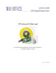
ME-110
Unicoder
Product Manual
Entry Level Incremental and Absolute High Resolution Encoder
1.0 4/8/2009
ME-110 Unicoder Features
absolute nonvolatile angle sensing
1024 positions per rotation
3.3 volt operation
readable angle
incremental quadrature and index pulse output
programmability (using Austria Microsystem’s AS5040 interface):
o index pulse location
o zero angle location
o resolution: 7, 8, 9, and 10 bit
o direction of rotation (CW or CCW)
o output modes: quadrature, sign-magnitude, or BLDC motor commutation
Description
Nubotics breaks new ground with this unique new sensor. Combining the
best of both incremental and absolute encoders, the Nubotics Unicoder
ME-110 solves many problems for electromechanical designers. And, as
the shaft and case are designed to replace rectangular potentiometers
used for angle sensing in many standard size RC servos, robot builders
now have a powerful new way to measure joint position, wheel velocity,
total distance travelled, and more.
Inside, the ME-110 contains an Austria Microsystems AS5040 magnetic
encoder chip, with a matching rare earth magnet carefully mounted above
the chip so that it can rotate over the center of the chip’s die. The
magnet’s N and S poles are radially aligned, so that no matter what the
magnet’s orientation is, the encoder chip’s 8 Hall effect sensors and DSP
can determine its absolute position. The chip also provides standard
quadrature incremental encoder outputs with a once-around index pulse.
By changing the mode of the chip, one can instead obtain sign/magnitude
outputs rather than quadrature. In yet another mode, it can even
generate 3 phase BLDC motor control signals.
The ME-110 is designed for low speed applications only, due to its reliance
on the bearing properties of ABS plastic.
Installation
Internal to an RC servo (continuous rotation):
The ME-110 Unicoder encoder can be press fit in the rectangular
depression inside a standard size RC servo (depending on make and
model) once the RC servo’s feedback potentiometer has been removed (a
common operation when converting an RC servo for continuous rotation
operation). By adding an ME-110 Unicoder encoder, a customer supplied
controller can accurately measure and control the operation of a
continuous rotation servo.
Internal to an RC servo (angle positioning):
In this application, the feedback between shaft angle, as sensed by the
ME-110, and control of the RC servo’s DC motor must be provided in one
of two ways:
1. External to the RC servo, a customer-developed controller
produces RC servo control pulses to drive the RC servo electronics,
while using the ME-110 as a feedback device, using a control
system such as a PID position loop to effect desired motion.
2. External to the RC servo, a customer-developed controller, which
includes a DC motor driver, directly controls the RC servo’s DC
motor itself, again using the ME-110 as a feedback device for the
customer’s control system.
NOTE: as the RC servo’s feedback potentiometer has to be removed to
Unicoder ME-110 Product Manual
3
allow the ME-110 to be mounted inside, the RC servo control circuit will no
longer be provided with the feedback signal it needs to close the loop and
thus control position. As a result, some other means must be provided as
described in points 1 and 2.
External to an RC servo (angle positioning):
By mechanically coupling the ME-110 Unicoder encoder to the RC servo
output shaft externally, the RC servo control electronics continue to
provide angle control using the internal potentiometer for feedback.
Meanwhile, the customer-provided controller can use the ME-110 Unicoder
encoder to sense the actual position of the shaft.
Other Applications:
The ME-110 Unicoder encoder is well suited for all kinds of rotary motion
sensing.
Shaft:
The ME-110 Unicoder encoder’s .125" diameter shaft is not designed to be
load bearing.
Case retention:
The case can be press fit in a hole properly undersized for the nominal
Unicoder dimention of .394” x .438”. Other mounting schemes are
possible.
Unicoder ME-110 Product Manual
4
Communications
The ME-110 Unicoder encoder makes the Austria Microsystems AS5040
signals available to the user; these signals include a PWM signal whose
duty cycle is proportional to shaft angle; Index, ChA, and ChB incremental
signals; and a unique synchronous serial programming and query
interface as specified on the AS5040 datasheet.
Note: data is transferred most significant bit first.
Querying is done by keeping Prog low, then asserting /CS low with CLK
high, then clocking the data using the CLK line. On each of 16
subsequent falling edges of CLK, sample the data on pin DO. Return CLK
high, then /CS high to end the transfer.
Programming is done by asserting CLK and /CS low, then raising Prog
high. After a delay, assert /CS high. After another delay, start
transferring data. Assert each data bit in turn on the Prog line, clocking it
in (after setting the Prog line to the value of the current bit) by raising
and lowering the CLK line. Repeat for all 16 data bits. Finally, end the
programming cycle with Prog and CLK low, while dropping /CS.
Please see the AS5040 data sheet for details, available here:
http://www.austriamicrosystems.com/eng/Products/MagneticEncoders/Rotary-Encoders/AS5040
Unicoder ME-110 Product Manual
5
AS5040 Query Register
Bit
Number
Name
Meaning
0
Parity
Even parity of bits 1-15 for transmission error detection
1
Mag DEC
High when magnet pulled away from IC
2
Mag INC
High when magnet pushed towards IC; both high when out of range
3
LIN
Linearity alarm; when high, Angle data may be invalid
4
COF
Cordic overflow; when high, Angle data is invalid
5
OCF
Offset compensation finished; high when data is valid
6-15
Angle
Absolute angular position
AS5040 Program Register
Bit
Number
Name
Meaning
0-1
Mode
output mode: 0: default; 1: quadrature; 2: sign/magnitude; 3:
BLDC commutation
2-3
Div
resolution: 0: 10 bit; 1: 9 bit; 2: 8 bit; 3: 7 bit
4
IndexLen
0: 1 pulse wide; 1: 3 pulses wide
5-14
Zero/Idx
location of zero angle and index pulse (always 10 bit
resolution)
15
CCW
0: angle increases clockwise; 1: angle increases counter
clockwise
Servo Compatibility
The ME-110's rectangular shape fits in the potentiometer recess of some
makes and models of hobby servos. The following is an incomplete list.
Manufacturer
Model
GWS
S03N
S03T
S03TXF
S06
Hitec
HS322HD
Note: if your specific servo is not listed, it may still fit. However, you will
have to open up the servo case to determine the shape and size of the
potentiometer. Many models use a round potentiometer, the result of
which is that the currently shipping versions of the ME-110 would be
incompatible. Opening of any RC servo will most likely violate it’s
manufacturer’s warranty.
Unicoder ME-110 Product Manual
6
Connector Pinout
Pin
Mode
Quadrature
Sign/Magnitude
1
MagDec
2
MagInc
Description
Commutation
open drain reduced magnetic field indicator
open drain increased magnetic field indicator
3
PWM
PWM
LSB
4
Index
Index
W
1KHz PWM signal, where duty cycle indicates angle
once-around index pulse or BLDC motor W phase
5
/CS
chip select; pull low to enable ChA/ChB after power on
6
Vdd
+3.3v max
7
DO
data out of synchronous serial interface
8
Clk
clock for synchronous serial interface
9
ChB
DIR
V
quadrature B, rotation direction, or BLDC V phase
10
ChA
CLK
U
quadrature A, rotation clock, or BLDC U phase
11
Prog
data in for synchronous serial interface
12
Gnd
ground
Unicoder ME-110 Product Manual
7
Specifications
Value
Min
Max
Units
Supply Voltage, Vcc
3.0
3.6
Volts
Supply Current
16
21
mA
Resolution
64
1024
Ticks/360"
PWM Frequency
975.6
Hz
PWM Period
1025
µs
PWM Duty Cycle
1
1024
µs
Query Clock Rate
>0
1000
KHz
Programming Clock Rate
>0
250
KHz
Shaft Speed
0
240
RPM
Shaft Diameter
.125
Shaft Length
.375
Case Width
.394
Case Length
.438
PCB Width
.500
PCB Length
.700
Overall Width
.560
Overall Length
.713
Overall Height
.955
inches
Interfacing Examples
Please visit www.nubotics.com to view and download example
code for Ridgesoft RoboJDE Java and other controllers.
{contact Nubotics for correct URL – these are not public yet}
Document History
Rev 1.0 - initial draft
For more information visit: www.nubotics.com
Produced by Noetic Design, Inc., 25 NW 23rd PL, STE 6 PMB 181, Portland OR 97210
Copyright ©2009 Noetic Design, Inc. All rights reserved
Unicoder ME-110 Product Manual
8