Download DIGITAL I/O CARD

Transcript
DIO9201
Digital I/O Card
User’s Manual (V1.3)
健昇科技股份有限公司
JS AUTOMATION CORP.
新北市汐止區中興路 100 號 6 樓
6F., No.100, Zhongxing Rd.,
Xizhi Dist., New Taipei City, Taiwan
TEL:+886-2-2647-6936
FAX:+886-2-2647-6940
http://www.automation.com.tw
http://www.automation-js.com/
E-mail:[email protected]
Correction record
Version
V1.2->V1.3
Record
Modify 4. Layout and dimensions
5. Pin definitions
6. I/O interface diagram
1
Contents
1.
Forward ................................................................................................................................................ 4
2.
Features ................................................................................................................................................ 5
2.1 Main card ................................................................................................................................... 5
2.2 Din rail mounted wiring board................................................................................................... 5
Specifications ....................................................................................................................................... 6
3.1 DIO9201 Main card ................................................................................................................... 6
3.2 Din rail mounted wiring board................................................................................................... 7
Layout and dimensions ........................................................................................................................ 8
4.1 DIO9201 Main card ................................................................................................................... 8
4.2 ADP9201DIN Din rail mounted wiring board .......................................................................... 8
4.3 JS51053 for CN1/CN2 20PM Din rail mounted dummy wiring board ..................................... 9
3.
4.
5.
Pin definitions .................................................................................................................................... 10
6.
I/O interface diagram ......................................................................................................................... 11
6.1 Input diagram ........................................................................................................................... 11
6.2 Output diagram ........................................................................................................................ 12
External wiring diagram .................................................................................................................... 13
Installation ......................................................................................................................................... 14
8.1 Card address setting ................................................................................................................. 14
8.2 I/O descriptions ........................................................................................................................ 14
Noise immunity and the use of watch-dog timer ............................................................................... 15
7.
8.
9.
10. Ordering information ......................................................................................................................... 16
2
Notes on hardware installation
Please follow step by step as you are installing the control cards.
1. Be sure your system is power off.
2. Be sure your external power supply for the wiring board is power off.
3. Plug your control card in slot, and make sure the golden fingers are put in right contacts.
4. Fasten the screw to fix the card.
5. Connect the cable between the card and wiring board.
6. Connect the external power supply for the wiring board.
7. Recheck everything is OK before system power on.
8. External power on.
Congratulation! You have it.
For more detail of step by step installation guide, please refer the file “installation.pdf “ on the CD
come with the product or register as a member of our user’s club at:
http://automation.com.tw/
to download the complementary documents.
3
1. Forward
Thank you for your selection of DIO9201 DIGITAL I/O card for industrial IBM compatible PC.
In the field of industrial control, digital I/O is generally controlled under a microprocessor, and
owing to their specific consideration of industrial environment, it is quite different from the laboratory
requirement.
JS Automation Corp. has been in this field more than ten years and got the know-how of preventing
noise interfered from the I/O circuit, which makes the difference from others, and we wish the card that
will be helpful to your project.
Other DIO series products:
DIO2232 32 channel input and 32 channel output isolated digital I/O card (ISA bus)
DIO2248 48 channel input and 16 channel output isolated digital I/O card (ISA bus)
DIO2264 64 channel input isolated digital I/O card (ISA bus)
DIO3206 48 channel TTL digital I/O Card (PCI bus)
DIO3208B 8 channel input and 8 channel relay output isolated digital I/O card (PCI bus)
DIO3216B 16 channel input and 16 channel output isolated digital I/O card (PCI bus)
DIO3217 16 channel input and 16 channel output isolated digital I/O card (PCI bus)
DIO3232
DIO3248
DIO3264
DIO4264
DIO6208
DIO6216
with multifunction timer/counter
32 channel input and 32 channel output isolated digital I/O card (PCI bus)
48 channel input and 16 channel output isolated digital I/O card (PCI bus)
64 channel input isolated digital I/O card (PCI bus)
64 TTL digital I/O PC-104 Module
8 channel input and 8 channel relay output isolated digital I/O PCI-104 Module
16 channel input and 16 channel relay output isolated digital I/O PCI-104 Module
Any comment is welcome,
please visit our website
http://www.automation.com.tw/
http://www.automation-js.com/ for the up to date information.
4
2. Features
2.1 Main card
2.1.1
Photo-isolated circuit design provides high noise immunity.
2.1.2
I/P debounce circuit prevents jittering I/P.
2.1.3
Hardware prohibited power-on transient at O/P.
2.1.4
Provide 16 photo-isolated I/P and 16 photo-isolated O/P per card.
2.1.5
Each O/P has free-wheel diode and its drive capacity is 500mA.
2.1.6
On board WDT (watch-dog timer) to shutdown O/P during computer is malfunction.
2.1.7
Two flat cables, easy connect to terminal board.
2.1.8
Half card size, fit for all type of PC.
2.2 Din rail mounted wiring board
2.2.1
ADP9201DIN
2.2.2
JS51053
Din rail mounted wiring board
20P Din rail mounted dummy wiring board
5
3. Specifications
3.1 DIO9201 Main card
Digital Input
3.1.1
Input : 16 photo-isolated
3.1.2
ON State : 2.8Vdc(max) 4.5mA(min)
3.1.3
OFF State : 8Vdc(min) 3mA(max)
3.1.4
Switching Speed : 2.2KHz max. ( with on board debounce circuit)
Digital Output
3.1.5
Output : 16 photo-isolated
3.1.6
Output Range : Open collector 0 ~ 45 Vdc (on card)
3.1.7
Output Rating : 3A @250Vac, 30Vdc (Relay)
1A @ 24Vdc (PMOS)
2A @ 240Vac (SSR)
3.1.8
Sink Current : 500mA(peak) per channel (on card)
3.1.9
Switching Speed : 20KHz(max)(MOS out only)
General
3.1.10 Insulation Resistance : 100M Ohm (min) at 1000Vdc
3.1.11 Isolation Voltage : 2500Vac 1Min
3.1.12 Connector : Two 20-pin male flat-cable connectors
3.1.13 Operation Temperature : 0 to +70 degree C
3.1.14 Storage Temperature : -20 to +80 degree C
3.1.15 Operation Humidity : 5~95% RH, non-condensing
3.1.16 Dimensions : 175(W)*110(H) mm , 6.9(W)*4.4(H)in
6
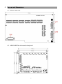
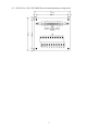
3.2 Din rail mounted wiring board
ADP9201DIN Din rail mounted wiring board
3.2.1
External Supply : DC 24V ± 4V
3.2.2
Input : 8 with LED indicator
3.2.3
Output: ADP9201DIN(R) : 8 relays (3A @250Vac, 3A @30Vdc) with LED
indicator
ADP9201DIN(S) : 8 SSR (2A @240Vac) with LED indicator
ADP9201DIN(P) : 8 PMOS (Source 1A @24Vdc) with LED
Indicator
3.2.4
Connector: One 20-pin male flat-cable connector
3.2.5
Operation Temperature: 0 to +70 degree C
3.2.6
Operation Humidity: RH5~95%, non-condensing
3.2.7
Dimension: ADP9201DIN(R) / (P) : 86(W) * 103(L) *45(H)mm;
3.4(W)*4.1(L)*1.8(H)in
ADP9201DIN(S) : 86(W) * 103(L) *50(H)mm
3.4(W)*4.1(L)*2.0(H)in
JS51053 20P Din rail mounted dummy wiring board
3.2.8
Dimension: 86(W)*79(L)*52(H)mm, 3.4(W)*3.2(L)*2.1(H)in
7
4. Layout and dimensions
4.1 DIO9201 Main card
4.2 ADP9201DIN Din rail mounted wiring board
8
4.3 JS51053 for CN1/CN2 20PM Din rail mounted dummy wiring board
9
5. Pin definitions
PIN
1
3
5
7
9
11
13
15
17
19
Descriptions
EXT_IN0
EXT_IN1
EXT_IN2
EXT_IN3
EXT_IN4
EXT_IN5
EXT_IN6
EXT_IN7
EXTG
+24Ve
PIN
2
4
6
8
10
12
14
16
18
20
Descriptions
EXT_OUT0
EXT_OUT1
EXT_OUT2
EXT_OUT3
EXT_OUT4
EXT_OUT5
EXT_OUT6
EXT_OUT7
EXTG
+24Ve
PIN
1
3
5
7
9
11
13
15
17
19
Descriptions
EXT_IN8
EXT_IN9
EXT_IN10
EXT_IN11
EXT_IN12
EXT_IN13
EXT_IN14
EXT_IN15
EXTG
+24Ve
PIN
2
4
6
8
10
12
14
16
18
20
Descriptions
EXT_OUT8
EXT_OUT9
EXT_OUT10
EXT_OUT11
EXT_OUT12
EXT_OUT13
EXT_OUT14
EXT_OUT15
EXTG
+24Ve
10
6. I/O interface diagram
6.1 Input diagram
11
6.2 Output diagram
Type 1 output : (PMOS)
Type 2 output : (Relay)
Type 3 output : (SSR)
12
7. External wiring diagram
wiring board with Relay output
wiring board with SSR output
wiring board with PMOS output
13
8. Installation
8.1 Card address setting
The DIO9201 card occupied 4 I/O addresses and can be set at any location by DIP switch on
card.
Any DIP switch set "on" position means a "zero" in the corresponding address line and a "off"
position means a "one" in the corresponding address line.
For example, we wish to set the card address at 280h - 283h. We should set as follows:
p.s. A1 and A0 are forced to “zero” setting
8.2 I/O descriptions
READ
BASE ADDRESS
BASE ADDRESS+1
BASE ADDRESS+2
BASE ADDRESS+3
WRITE
I/P DATA FROM CN1
I/P DATA FROM CN2
UNDEFINE
UNDEFINE
O/P DATA TO CN1
O/P DATA TO CN2
UNDEFINE
DISABLE WDT
Be sure to check the I/O address to prevent conflict with other cards.
To prevent the transient and undefine states occurred mistakes to O/P during power on stage,
the hardware prohibited by a protection circuit. The protection will not release to work until
first writing O/P data on both CN1 and CN2 be finished. After the writing, the O/P of CN1 and
CN2 will simultaneously enabled.
14
9. Noise immunity and the use of watch-dog timer
Any malfunction of computer hardware or software will cause mistakes result on O/P’s, and
meanwhile cause a harm. The causes of malfunctions are mainly noise, which is generated from external
inductance load at random.
JS Automation Corp. put special emphasis on the noise immunity of I/O interface which is often
mishandled by some designer (maybe they put much effort on power line noise, but the result is not so
significant as expected).
In addition to the noise immunity consideration, we also design a watch-dog timer to monitoring
the system I/O status. Basically , the watch-dog timer is a retriggerable timer, if the I/O has been
normally updated (update rate less than 1s) by the computer, it will do nothing but enable the O/P. If any
malfunction occurred and the computer does not update or the update rate too slow, the watch-dog timer
will disable all the O/P to prevent any harm.
To use DIO9201 card will help you:
1. To prevent the noise interference from the I/O.
2. To prevent malfunction of I/O.
We also provide 2 functions about the watch-dog timer:
Shorts the jumper will disable the function of watch-dog timer.
Write the base address+3 will temporary disable the watch-dog timer and any normal read or write to the
CN1 or CN2 port will restart the function.
15
10. Ordering information
PRODUCT
DESCRIPTIONS
DIO9201
32-channel Digital I/O Card for 16 DI and 16 D0 Photo-coupler isolated
ADP9201DIN(R) DIN rail mounted wiring board with 16 I/O LED indicators and relay
output for 8 DI, 8DO
ADP9201DIN(P) DIN rail mounted wiring board with 16 I/O LED indicators and PMOS
output for 8 DI, 8DO
ADP9201DIN(S) DIN rail mounted wiring board with 16 I/O LED indicators and SSR
output for 8 DI, 8DO
JS51053
DIN rail mounted dummy wiring board
M23207
20-pin flat cable 1.5 M
M23209
20-pin flat cable 3.0 M
16