1
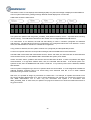
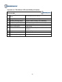
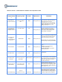
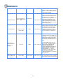
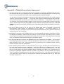
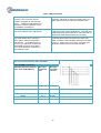
For ease of remembering, you can assign machine names based on location within a plant. For example:
Location
Pump #1
Motor #1 Shaft
Conveyor Belt #1
Conveyor Belt #2
Pump #2
Sensor Serial Number
1013-5186
1013-5187
1013-5188
1013-5189
1013-5190
Notes
X axis parallel to motor shaft
You will later use this information to configure the VTB system.
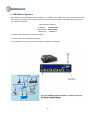
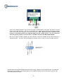
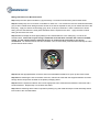
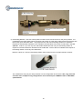
VTB Sensor network utilizes CAN Bus for digital communications. A 120 ohm terminating resistor must be placed
at the end of each CAN Bus line.
VTB Sensors can be connected to any CAN interface. Each interface provides 2 power outputs and 2-wire CAN
Bus. Connections to CAN terminals are identical on all 4 interfaces.
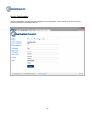
7. VTB System Web Configurator
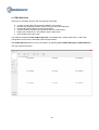
VTB System provides a built-in sub-system called VTB-COM WEB Configurator that gives administrators
abilities to manage all available features using a standard web browser.
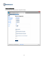
WEB configurator functionality:
●
Detects VTB Sensors on all CAN Bus interfaces
19