1
USER’S MANUAL
SPECTRUM III HYBRID READER
MAGSTRIPE & SMART CARD
Standard & Compact chassis
80064501-001-J
February 18, 2010
Copyright 2006-2010 International Technologies & Systems Corp. All rights reserved.
SPECTRUM III HYBRID MAGSTRIPE/SMART CARD READER
This equipment has not been tested to comply with Part 15 of the FCC Rules for a digital device.
This device is designed to be incorporated into a product that will be tested to comply with all
regulatory requirements.
CERTIFICATIONS
The spectrum III reader has passed EMV 2000 Terminal Level 1 testing on May 4, 2005. The
RS232 PC/SC driver was certified and signed by WHQL December 2003. The USB PC/SC driver
was certified and signed by WHQL May 9, 2005 and USB CDC is scheduled to be certified and
signed by WHQL. These drivers were certified with Windows 2000 and Windows XP (only the 32
bit versions). CE certification is in process.
LIMITED WARRANTY
ID TECH warrants to the original purchaser for a period of 12 months from the date of invoice that
this product is in good working order and free from defects in material and workmanship under
normal use and service. ID TECH’s obligation under this warranty is limited to, at its option,
replacing, repairing, or giving credit for any product which has, within the warranty period, been
returned to the factory of origin, transportation charges and insurance prepaid, and which is, after
examination, disclosed to ID TECH’s satisfaction to be thus defective. The expense of removal and
reinstallation of any item or items of equipment is not included in this warranty. No person, firm, or
corporation is authorized to assume for ID TECH any other liabilities in connection with the sales of
any product. In no event shall ID TECH be liable for any special, incidental or consequential
damages to Purchaser or any third party caused by any defective item of equipment, whether that
defect is warranted against or not. Purchaser’s sole and exclusive remedy for defective equipment,
which does not conform to the requirements of sales, is to have such equipment replaced or
repaired by ID TECH. For limited warranty service during the warranty period, please contact ID
TECH to obtain a Return Material Authorization (RMA) number & instructions for returning the
product.
THIS WARRANTY IS IN LIEU OF ALL OTHER WARRANTIES OF MERCHANTABILITY OR
FITNESS FOR PARTICULAR PURPOSE.
THERE ARE NO OTHER WARRANTIES OR
GUARANTEES, EXPRESS OR IMPLIED, OTHER THAN THOSE HEREIN STATED. THIS
PRODUCT IS SOLD AS IS. IN NO EVENT SHALL ID TECH BE LIABLE FOR CLAIMS BASED
UPON BREACH OF EXPRESS OR IMPLIED WARRANTY OF NEGLIGENCE OF ANY OTHER
DAMAGES WHETHER DIRECT, IMMEDIATE, FORESEEABLE, CONSEQUENTIAL OR SPECIAL
OR FOR ANY EXPENSE INCURRED BY REASON OF THE USE OR MISUSE, SALE OR
FABRICATIONS OF PRODUCTS WHICH DO NOT CONFORM TO THE TERMS AND
CONDITIONS OF THE CONTRACT.
The information contained herein is provided to the user as a convenience. While every effort has
been made to ensure accuracy, ID TECH is not responsible for damages that might occur because
of errors or omissions, including any loss of profit or other commercial damage. ID TECH assumes
no responsibility, for its use, nor for any infringements or patents or other rights of third parties that
may result from its use. The specifications described herein were current at the time of publication,
but are subject to change at any time without prior notice.
ID TECH is a registered trademark of International Technologies & Systems Corporation. Spectrum
and Value through Innovation are trademarks of International Technologies & Systems Corporation.
Copyright 2006-2010 International Technologies & Systems Corp. All rights reserved.
Page 2 of 102
SPECTRUM III HYBRID MAGSTRIPE/SMART CARD READER
Table of Contents
1.
OVERVIEW AND INTRODUCTION ............................................................................ 7
1.1.
General.................................................................................................................. 8
1.2.
Features ................................................................................................................ 8
1.3.
Factory Installed Options ....................................................................................... 9
1.4.
Optional Accessories ............................................................................................. 9
1.5.
Spectrum I, Spectrum IIa, Spectrum II and Spectrum III Differences .................... 9
2.
DEFINITIONS, DOCUMENTS AND LINKS ............................................................... 10
2.1.
Definitions............................................................................................................ 10
Related Documents ......................................................................................................... 12
2.2.
Applicable Links................................................................................................... 12
3.
QUICK START .......................................................................................................... 13
3.1.
Quick Start Versions ............................................................................................ 13
3.2.
Required Equipment ............................................................................................ 13
3.3.
Installing Drivers .................................................................................................. 14
3.3.1.
Install PC/SC Driver....................................................................................... 14
3.3.2.
Install FTDI Driver.......................................................................................... 15
3.3.3.
Install CDC Driver .......................................................................................... 16
3.4.
Demonstration Programs..................................................................................... 17
3.4.1.
PC/SC Demonstration ................................................................................... 17
3.4.2.
Non-PC/SC Demonstration............................................................................ 18
3.5.
FAQ (Frequently Asked Questions) ..................................................................... 18
4.
PC/SC GENERAL DESCRIPTION ............................................................................ 20
4.1.
Purpose of PC/SC ............................................................................................... 20
4.2.
EMV verses PC/SC ............................................................................................. 20
4.3.
IdtLib.dll ............................................................................................................... 21
4.4.
How the Various Parts of the PC/SC Fit Together. .............................................. 21
5.
HYBRID READER—GENERAL AND ICC................................................................. 22
5.1.
Operation............................................................................................................. 22
5.1.1.
Smart Card Features ..................................................................................... 22
5.1.2.
Magnetic Card Read Modes .......................................................................... 22
5.1.3.
Latch Operation ............................................................................................. 22
5.1.4.
Smart Card Access........................................................................................ 23
5.1.5.
LED Handling................................................................................................. 23
5.1.6.
Lighted bezel option (4 LEDs) ....................................................................... 24
5.1.7.
Card Status Notification [B0 xx] or [2F 00] ..................................................... 25
5.2.
Communication Structure .................................................................................... 26
5.2.1.
Host Command.............................................................................................. 26
5.2.2.
Reader Response.......................................................................................... 26
5.2.3.
Example of LRC Calculation .......................................................................... 27
5.2.4.
Communication Timing .................................................................................. 27
5.3.
General Reader Commands Description ............................................................. 28
5.3.1.
Get Firmware Version Description [39] .......................................................... 28
5.3.2.
Get Reader Status [24] .................................................................................. 28
5.3.3.
Latch Close Command [4C 01]...................................................................... 29
5.3.4.
Latch Open Command [4C 00] ...................................................................... 29
5.3.5.
Host LED Control Command [6C].................................................................. 30
Copyright 2006-2010 International Technologies & Systems Corp. All rights reserved.
Page 3 of 102
SPECTRUM III HYBRID MAGSTRIPE/SMART CARD READER
5.3.6.
Reader Reset Command [49] ........................................................................ 30
5.3.7.
Get Copyright Information [38] NEW ............................................................. 30
5.3.8.
Enter Downloader (Upgrade Firmware) [7A] NEW ........................................ 31
5.4.
Reader Configuration Commands Description .................................................... 31
5.4.1.
Restore Configuration Settings to Default [53 18].......................................... 31
5.4.2.
Read All Configuration Settings [52 1F] ......................................................... 32
5.4.3.
Read Specific Configuration Setting [52 nn] .................................................. 33
5.4.4.
Set BAUD Rate [53 41] (RS232 only) ............................................................ 34
5.4.5.
Set Card Option [53 10] ................................................................................. 35
5.4.6.
Set Operation Mode [53 11]........................................................................... 36
5.4.7.
Set Compatibility Mode [53 1E] NEW ............................................................ 38
5.4.8.
Read Reader Serial Number [52 4E] ............................................................. 38
5.5.
Microprocessor Commands Descriptions ............................................................ 38
5.5.1.
Smart Card Commands Summary................................................................. 39
5.5.2.
Transmission Protocol for ICC Cards ............................................................ 39
5.5.3.
Power On (Get ATR) Command [6E]............................................................. 40
Power Off Command [4D]............................................................................................. 42
5.5.4.
ICC Reader Microprocessor Card Output Command Structure [41] .............. 42
5.5.5.
ICC Reader Microprocessor Card Input Command Structure [61]................. 43
5.5.6.
ICC Reader Microprocessor Card Raw T=1 Command Structure [46] .......... 44
5.5.7.
ISO 7816 Command Structure....................................................................... 46
5.6.
Memory Card Commands.................................................................................... 47
5.6.1.
General.......................................................................................................... 47
5.6.2.
ICC Reader Memory Card Command Structure [42] ..................................... 47
5.6.3.
Set Memory Card Type [53 12]...................................................................... 47
5.6.4.
Set Memory Card Page Write Size [53 15] .................................................... 47
5.7.
SAM—Secure Access Module Support ............................................................... 48
5.7.1.
SAM Purpose................................................................................................. 48
5.7.2.
Typical SAM Operation.................................................................................. 48
5.7.3.
ICC Connector Selection [43 0n] ................................................................... 49
5.7.4.
Set SAM Card Option [53 6n 02] ................................................................... 50
5.7.5.
SAM Card Operation Scenario ...................................................................... 50
5.7.6.
Notes for SAM Card Operation ...................................................................... 51
5.8.
Return Status Summary and Explanation............................................................ 51
6.
HYBRID READER—MAGNETIC STRIPE SUPPORT .............................................. 52
6.1.
Features .............................................................................................................. 52
6.1.1.
Message Format............................................................................................ 52
6.1.2.
Magnetic Stripe Data ..................................................................................... 52
6.2.
Features Description............................................................................................ 52
6.3.
Default Card Data Output .................................................................................... 53
6.4.
Buffered Mode Operation Commands ................................................................. 54
6.4.1.
Arm to Read Command [50 01 30] ................................................................ 54
6.4.2.
MSR Reset Command [50 01 32] .................................................................. 54
6.4.3.
Read MSR Data Command [51 01] ............................................................... 55
6.5.
MSR Configuration Commands Description ........................................................ 55
6.5.1.
MSR Transmit Mode Setting [53 1A] ............................................................. 56
6.5.2.
MSR Read Direction Setting [53 1D] ............................................................. 56
Copyright 2006-2010 International Technologies & Systems Corp. All rights reserved.
Page 4 of 102
SPECTRUM III HYBRID MAGSTRIPE/SMART CARD READER
6.5.3.
MSR Send Option Setting [53 19].................................................................. 56
6.5.4.
MSR Data Terminator Setting [53 21]............................................................ 56
6.5.5.
MSR Data Prefix String Setting [53 D2] ......................................................... 57
6.5.6.
MSR Data Suffix String Setting [53 D3] ......................................................... 57
6.5.7.
Track ID Setting [53 3n] ................................................................................. 57
6.5.8.
Track Selection Setting [53 13] ...................................................................... 58
6.5.9.
Track Separator Setting [53 17] ..................................................................... 58
7.
PC/SC APPLICATION PROGRAMMING IN C++...................................................... 59
7.1.
PC/SC Programming Overview ........................................................................... 59
7.2.
SCardEstablishContext........................................................................................ 59
7.3.
SCardConnect ..................................................................................................... 59
7.4.
SCardTransmit .................................................................................................... 59
7.5.
SCardDisconnect................................................................................................. 60
7.6.
SCardReleaseContext ......................................................................................... 60
8.
HYBRID READER DEMONSTRATION SOFTWARE................................................ 65
8.1.
HRDLL Demo Program Non-PC/SC .................................................................... 65
8.2.
PC/SC Visual C++ Demonstration Program ........................................................ 65
8.2.1.
Requirement .................................................................................................. 66
8.2.2.
Installation ..................................................................................................... 66
8.2.3.
Operation ....................................................................................................... 66
8.2.4.
Program Source Code: .................................................................................. 68
8.3.
PC/SC Visual Basic Demonstration Program ...................................................... 68
8.3.1.
Requirement .................................................................................................. 68
8.3.2.
Installation ..................................................................................................... 69
8.3.3.
Launching ...................................................................................................... 69
8.3.4.
Operation ....................................................................................................... 69
8.3.5.
Program Source Code ................................................................................... 70
9.
SPECIFICATIONS..................................................................................................... 71
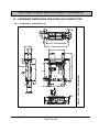
10. HARDWARE DIMENSIONS, MOUNTING AND CONNECTORS.............................. 73
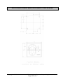
10.1. Dimensions of Spectrum III.................................................................................. 73
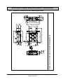
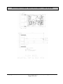
10.2. Dimension of Spectrum III with SAM daughter board .......................................... 74
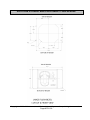
10.3. Dimension of Spectrum III Compact chassis with its bezel.................................. 75
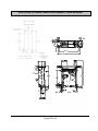
10.4. Mounting.............................................................................................................. 76
10.5. Hybrid Reader Connectors .................................................................................. 76
10.6. Hybrid Reader Bezel information......................................................................... 77
11. APPENDIX A: SPECIAL INSTALLATION INSTRUCTIONS...................................... 84
11.1. Installing Unsigned Driver Over Signed Drivers................................................... 84
11.2. Configuring to Allow Installation of Unsigned Drivers .......................................... 84
11.3. Configuring to Display System Files .................................................................... 84
11.4. Configuring the Smart Card Service .................................................................... 85
11.5. Reconnecting a Disconnected Reader ................................................................ 85
11.6. Configuring PC to Support Serial Plug and Play.................................................. 85
12. APPENDIX B: ID TECH PC/SC IDTLIB.DLL GUIDE ................................................. 86
13. APPENDIX C: DOWNLOADING ............................................................................... 95
14. APPENDIX C: Complete List of Response Codes..................................................... 96
15. INDEX...................................................................................................................... 100
16. LIMITATIONS .......................................................................................................... 102
Copyright 2006-2010 International Technologies & Systems Corp. All rights reserved.
Page 5 of 102
SPECTRUM III HYBRID MAGSTRIPE/SMART CARD READER
Table of Figures and Tables
Figure 1 – Orientation for Inserting Card into Reader......................................................... 17
Figure 2 – Simplified PC/SC Component Organization ...................................................... 21
Figure 3 – Spectrum III Dimensions ................................................................................... 73
Figure 4 – Spectrum III Dimensions With SAM Daughter Board ........................................ 74
Table 1 – Reader Command ID Summary ......................................................................... 28
Table 2 – Default MSR Configuration Settings ................................................................... 31
Table 3 – Configuration Function ID Summary and Explanation ........................................ 33
Table 4 – Reader Command IDs Affecting Smart Card Summary...................................... 39
Table 5 – Response Status Code Summary and Explanation ............................................ 51
Table 6 – Magnetic Stripe Message Formatting ................................................................. 52
Table 7 – SCARD Error to Value ........................................................................................ 60
Table 8 – SCARD Error Text Description ........................................................................... 62
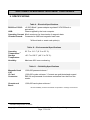
Table 9 – Electrical Specifications ...................................................................................... 71
Table 10 – Environmental Specifications............................................................................ 71
Table 11 – Reliability Specifications ................................................................................... 71
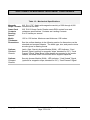
Table 12 – Mechanical Specifications ................................................................................ 72
Table 13 – SCARD Routine Return Values ........................................................................ 92
Copyright 2006-2010 International Technologies & Systems Corp. All rights reserved.
Page 6 of 102
SPECTRUM III HYBRID MAGSTRIPE/SMART CARD READER
1. OVERVIEW AND INTRODUCTION
ID TECH’s Intelligent Hybrid Insert Reader supports both magnetic stripe card
reading, and smart cards or IC cards. The reader communications are RS232 or
USB. The reader communicates with the host using a generic protocol. The USB
and PC/SC reader versions communicate with a driver running on a Windows PC.
There are two chassis types used for the Spectrum III Hybrid Insert Readers.
The standard chassis is generally form & fit equivalent to industry standards used
typically in POS & ATM applications and a full variety of options. The compact
chassis is smaller and is fitted with a single smaller sized bezel and is used typically
in applications where a smaller profile is wanted. The compact chassis does not
provide the card latch, front switch, and debris gate options. The same PCA design
and features are used on both chassis types.
This manual is a design guide for installing and interfacing the Spectrum III
(abbreviated SPT3) reader. To a PC the SPT3 can appear as either a COM device
or a PC/SC reader. If one is programming a PC/SC reader, for the most part, it will
be unnecessary to know the details of the communication between the PC and the
reader. This document briefly describes the standard PC/SC v1.0 interface. If one
has already programmed a PC/SC reader into your application and you now wish to
change readers perhaps to add triple track magnetic stripe reading or memory cards
then one should study the interface to the ID TECH provided idtlib.dll. This should
allow easy integration of these features into your application.
If one has programmed for an earlier RS232 version of a Spectrum reader the SPT3
should be able to replace that reader. The SPT3 also supports a USB interface that
is compatible with an application written for an RS232 Spectrum reader.
The following sections define the required protocols for communicating with, and
performing operations to an IC card. All T=0 and T=1 microprocessor cards are
supported. Check with your ID TECH representative for information on the types of
memory IC cards supported.
PC/SC is a standard interface between a smart card reader and a PC. The PC/SC
driver converts the PC/SC commands to the commands used natively by the reader.
This makes it convenient for the programmer to develop an application without being
committed to a particular reader. The PC/SC interface only defines T=0 and T=1
microprocessor interface cards. For functions that access the other features of the
reader beyond these cards such as magnetic stripe reading, latching, memory cards
and SAM support, the PC/SC interface supports these functions with vendor specific
calls. A DLL is available to aid the programmer in interfacing to these functions. This
document describes the PC/SC programming and sample programs that show how
to access these features. These sample programs are available on request.
The PC/SC driver only supports Windows 2000, Windows XP (32 bit only), and XP
embedded.
Copyright 2006-2010 International Technologies & Systems Corp. All rights reserved.
Page 7 of 102
SPECTRUM III HYBRID MAGSTRIPE/SMART CARD READER
1.1.
General
The Spectrum III reader is an intelligent manually operated insert reader for Smart
Cards (ICC) and up to three tracks of magnetic stripe data. This unit can interface
with asynchronous (microprocessor) types of integrated circuit cards, which conform
to ISO 7816-3. It can also interface with a variety of synchronous (memory) ICC
types. Units feature a large debris opening, which allows foreign matter such as coin
or paper, to fall or be forced out of the card slot.
1.2.
Features
• ISO 7816 and EMV 2000 compliant. Supports microprocessor cards requiring
a variety of f/d ratios (speeds). Supports ICC speeds from 9600 bps to 76.8k
bps.
• PC/SC Certified on Windows 2000 and Windows XP operating systems.
• Reads and writes microprocessor cards using both T=0 and T=1 protocols.
• RS232 or USB 2.0 full speed compatible.
• Uses turbo TLP-224 communication protocol to talk with the host.
• Allows the host to interrogate the device about current status and
configuration information and can notify the host automatically when a status
change occurs.
• 3 and 5-Volt ICCs support (including SAM support).
• Supports memory card types: 3-byte I2C, 4-byte I2C, SLE4404 SLE4406,
SLE4418, SLE4428, SLE4432, SLE4442, AT88SC101, et al.1
• Large debris slot
• Supports LED control; control either by the reader or by host commands
• Supports buffered and un-buffered modes and formatted or raw data
magnetic read.
• Supports in field firmware upgrade.
1
Contact ID TECH sales for a complete list of memory cards supported.
Copyright 2006-2010 International Technologies & Systems Corp. All rights reserved.
Page 8 of 102
SPECTRUM III HYBRID MAGSTRIPE/SMART CARD READER
1.3.
Factory Installed Options
•
•
•
•
•
•
•
•
•
1.4.
A dual color, single bulb LED is available.
Various bezel options available on the standard chassis.
A compact chassis option is available for a smaller profile
Conformal coating (on active electrical components).
Latching mechanism to secure a card in the reader.
SAM (Secure Application Module),
If more than one SAM is required, a 5 SAM daughter board connectors
Gate—this prevents foreign objects from easily entering the reader.
12V supply support with separate supply board (only one SAM supported).
Optional Accessories
DB9 serial cable assembly with female plug for AC/DC adapter.
USB adaptor cables of various standard lengths.
AC/DC power adapter complying with your specified power requirements.
PC/SC sample demonstration programs in Visual C++ and Visual Basic.
Smart card demonstration software for exhibiting the capabilities of the
Spectrum 3 reader in non-PC/SC mode.
• A configuration program to configure the reader’s optional capabilities.
• A sample initialized T=0 microprocessor smart card. P/N 8005206-001
• A sample initialized 2K byte memory smart card. P/N 8005205-001
•
•
•
•
•
1.5.
Spectrum I, Spectrum IIa, Spectrum II and Spectrum III Differences
• Successor to the Spectrum I, Spectrum IIa, and Spectrum II series hybrid
readers. This reader supports nearly all features of the earlier readers and is
backwards compatible with the Spectrum II reader.
• Field updating the reader code allows updating smart card support in this
rapidly changing industry.
• A Spectrum III Reader supports RS232 or USB 2.0 full speed.
• Restored support for certain memory card types removed in some
intermediate versions due to hardware limitations.
• Enhances Secure Application Module (SAM) support
• Host controlled and flashing LED support
• Code space available for additional features as the need arises.
ID TECH is committed to working with users to meet your special requirements.
Copyright 2006-2010 International Technologies & Systems Corp. All rights reserved.
Page 9 of 102
SPECTRUM III HYBRID MAGSTRIPE/SMART CARD READER
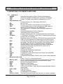
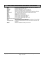
2. DEFINITIONS, DOCUMENTS AND LINKS
2.1.
Definitions
AAMVA
American Association of Motor Vehicle Administrators
ASCII
American Standard Characters for Information Exchange
ATR
Answer To Reset—the power on response from a ICC
Asynchronous card
a microprocessor ICC, that follows ISO7816-3
BPI
Bits Per Inch
BAUD
Roughly the RS232 communication in bits per second
CDC
Communication Device Class, this allows a USB reader to
appear as a COM device to a PC application.
Coercivity
The resistance of a magnetic field to change measured in
Oersteds.
C-APDU
Command-Application Protocol Data Unit
CDL
California Drivers License format
EMV
Europay-MasterCard-Visa—Financial transaction certification
F/D Ratio
F=Frequency, D=Divisor. In ISO 7816-3, these terms specify the
speed of the ICC interface.
FTDI
Hardware support for allowing a RS232 device to communicate
USB to PC but appears to an application as a RS232 device.
Gate
A device preventing easy entry of anything except a card into
the reader. This can limit dust and debris from getting inside.
Host
The Personal Computer to which the reader is attached.
IFD
Interface Device—this is how ISO 7816 refers to the reader.
IFS
Information Field Sizes, see ISO7816-3 section 9.5.2
IC, ICC
Integrated Circuit Card
IPS
Inches Per Second
ISO
International Standards Organization
Hex
Hexadecimal, base 16
Hybrid
Combination of two technologies here Smart Card and MSR
LED
Light Emitting Diode
LRC
Longitudinal Redundancy Check a form of error check character
Microprocessor card
Either T=0 or T=1 asynchronous card
Memory card
An ICC, commands supported vary by manufacturer, generally
simpler and less expensive than microprocessor cards.
MSDN
Microsoft Developers Network
MSR
Magnetic Stripe Reader
OLE
Object Linking and Embedding
OPOS
OLE for Point Of Sale, driver decodes magnetic stripe data into
logical fields
PnP or PNP
Plug-and-Play
PC
Personal Computer
PCA
An assembled Circuit Board
PC/SC or PCSC
Personal Computer/Smart Card interface, an industry standard
Copyright 2006-2010 International Technologies & Systems Corp. All rights reserved.
Page 10 of 102
SPECTRUM III HYBRID MAGSTRIPE/SMART CARD READER
PPS
Protocol and Parameters Selection, see ISO7816-3 section 7.2
PSC
Programmable Security Code
R-APDU
Response-Application Protocol Data Unit
RS232
Reference Standard serial communication
SAM
Secure Access Module also called Secure Application Module.
Smart Card
ICC, includes both memory and microprocessor cards
Sp2
Abbreviation for Spectrum II
SPT3
Abbreviation for Spectrum III
SPT3c
SPT3 firmware supporting USB CDC
SPT3s
SPT3 firmware supporting RS232
SPT3u
SPT3 firmware supporting USB PC/SC
Synchronous card see Memory card
USB
Universal Serial Bus—a high speed connection to the host that
also provides the reader with power
Transport code
A password used between the ICC manufacturer and the card
customer.
WHQL
Windows Hardware Quality Control Labs
Copyright 2006-2010 International Technologies & Systems Corp. All rights reserved.
Page 11 of 102
SPECTRUM III HYBRID MAGSTRIPE/SMART CARD READER
Related Documents
Published Documents
EMV 2000 Integrated Circuit Card Specifications for Payment Systems 4.0 (2000)
ISO 7810
Identification cards – Physical characteristics (1995)
ISO 7811
Identification cards –Recording technique (1995)
ISO/IEC 7816
Identification Cards - Integrated circuit(s) cards with contacts
Part 2: Dimension and location of the contacts (1989, DIS 1998)
Part 3: Electronic signals and transmission protocols (1997)
Part 4: Inter-industry commands for interchange (1995/Amd.1:1997)
Amd1: Impact of secure messaging on the structures of APDU messages.
ISO 10202-4 Financial transaction cards—Security architecture of financial
transactions systems using integrated circuit cards—Part 4: Secure
application modules
AAMVA
Best Practices Guidelines for the Use of Magnetic Stripes
PC/SC Workgroup Specifications Versions 1.0 and 2.0
ID TECH Documents
80064502-001 SPT3 Memory Card Manual
80064503-001 SPT3 Down Load Manual
80064506-001 SPT3 Returned Statuses Manual
2.2.
Applicable Links
AAMVA
EMV
ID TECH
MSDN
PC/SC
Windows Logo
OPOS
ISO documents
http://www.aamva.org/
http://www.emvco.com/
http://www.idtechproducts.com/
http://msdn.microsoft.com/library/
http://www.pcscworkgroup.com/
http://www.microsoft.com/whdc/winlogo/default.mspx
http://monroecs.com/opos.htm
http://www.iso.ch/
Note: All numeric characters are presented in hexadecimal, except numbers in
single quotes are in ASCII.
Copyright 2006-2010 International Technologies & Systems Corp. All rights reserved.
Page 12 of 102
SPECTRUM III HYBRID MAGSTRIPE/SMART CARD READER
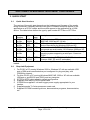
3. QUICK START
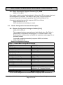
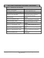
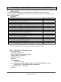
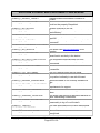
3.1.
Quick Start Versions
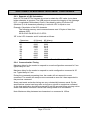
The version of the quick start depends on the hardware and firmware of the reader
being connected. Generally there are two types of readers those that appear to the
application as a PC/SC reader and those that appear to the application as a COM
device. The table below defines the type by part number SPT3 8xx or SPT3 5xx.
4
part
number
SPT3 84x
or 54x
SPT3 85
or 55x
SPT3 86x
or 56x
SPT3 88x
or 58x
type
description
USB reader using FTDI driver. compatible with Windows
98SE, ME, 2000 and XP (32 bit).
5
USB reader using Microsoft’s standard Communication
Device Class driver for Windows 2000 and XP.
6
Serial reader with ID TECH’S PC/SC driver. This reader
can operate as serial reader. OS Windows 2000 and XP.
8
Standard serial reader no driver required will work in any
operating system supporting a serial port. Cannot do
PC/SC.
9 SPT3 89x USB
SPT3 USB reader using ID TECH’S USB PC/SC driver for
or 59x
PC/SC u*
Windows 2000, XP and XP embedded.
*These readers have identical hardware the only difference being which firmware is
loaded.
3.2.
1.
2.
3.
4.
5.
6.
7.
USB
RS232
USB
CDC
RS232
PC/SC
RS232
firmware
SPT3
s
SPT3
c*
SPT3
s
SPT3
s
Required Equipment
For PC/SC a PC running Windows 2000 or Windows XP with an available USB
port or DB9 serial communication port configured for plug and play, with
CDROM or internet.
For Non-PC/SC a PC running Windows 98SE, ME, 2000 or XP with an available
USB port or and RS232 port (DB-9) and any computer.
ID TECH SPT3 hybrid reader in default configuration.
Supplied USB cable or RS232 serial cable.
If RS232 the supplied 5 volt wall hugger power supply appropriate for your
location.
Supplied sample T=0 microprocessor smart card.
Supplied CD-ROM containing drivers, demonstration programs, documentation,
etc.
Copyright 2006-2010 International Technologies & Systems Corp. All rights reserved.
Page 13 of 102
SPECTRUM III HYBRID MAGSTRIPE/SMART CARD READER
3.3.
Installing Drivers
If a SPT3 reader was ever installed it will install without prompting for the driver
installation disk. The reader should be up and ready to work, go to the install
demonstration software. If running a RS232 reader in non-PC/SC mode no driver is
required, go to 3.4 Demonstration on page 17. If installing a PC/SC reader go to
3.3.1 Install PC/SC Driver page 14. If installing a USB-FTDI reader go to 3.3.2 Install
FTDI Driver page 15. The final choice is installing USB-CDC driver go to 3.3.3 Install
CDC Driver page 16.
3.3.1. Install PC/SC Driver
The ID TECH PC/SC drivers were designed for Windows 2000, Windows XP (32
bit) and Windows XP embedded systems. Drivers connect a SPT3 USB or RS232 to
the operating system. The following installation instructions assume the reader is
being installed on Windows XP, the instructions for Windows 2000 will vary
somewhat.
If USB PC/SC Reader
1. Connect USB cable between SPT3 and PC.
2. When the new hardware found balloon displays select it.
3. The found new hardware wizard will display.
4. Accept the default, “Install Software Automatically.”
5. At the next prompt “If your hardware came with an installation CD or floppy
insert it now.” If not already done insert the provided CD.
6. At the last prompt, “Your device has been successfully installed,” click finish.
7. Go to 3.4.1 PC/SC Demonstration on page 17.
If RS232 PC/SC Reader
1. Connect RS232 cable between SPT3 and PC. Plug wall hugger power supply
to external power and connect power jack to back of the DB9 connector and
boot or reboot PC. (Instead of rebooting the user can also scan for new
hardware. Insert the CD that came with your hardware. To scan for new
hardware select ‘Start’ [then ‘Settings’] then ‘Control Panel’ [then
‘Performance and Maintenance’] then [‘Printers and other Hardware’] then
‘Add Hardware’ then ‘Next’ then ‘Add/Troubleshoot a device’ then click Next).
Items in square brackets maybe required depending on your windows
configuration settings.
2. When the new hardware found balloon displays select it. (If the PC boots
without detecting new hardware, it is probably not configured for plug and
play. If the LED remains amber after the PC has booted this is the case. See
instructions 11.6 Configuring PC to Support Serial Plug and Play, page 85).
3. The found new hardware wizard will display. To the prompt can Windows
connect to Windows update to search for this software, select “yes—this time
only.” Then click Next.
4. If prompted, “If your hardware came with an installation CD or floppy insert it
now.” Insert the provided CD. This is only necessary if your PC was unable to
contact the Microsoft site and download the correct driver.
Copyright 2006-2010 International Technologies & Systems Corp. All rights reserved.
Page 14 of 102
SPECTRUM III HYBRID MAGSTRIPE/SMART CARD READER
5. If prompted 'This wizard helps you to install software for: “ID TECH Spt3
Hybrid EMV Card Reader,”' Leave the default check box “Install the software
automatically (Recommended)” and click Next. Wait while the PC finds the
proper driver to install and installs it.
6. At the last prompt, “The wizard has finished installing the software for: “ID
TECH Spectrum II Magstripe and EMV Card Reader” click finish. The reason
the wizard says that Spectrum II reader installed is because the RS232
PC/SC driver is identical between the Sp2 and SPT3.
7. Select ‘Start’ [then ‘Settings’] then ‘Control Panel’ [then ‘Performance and
Maintenance’] then ‘Administrative Tools’ then ‘Services’. Then scroll down to
smart card. Verify that the Smart card service is started and that the start-up
type is automatic. You can do this by double clicking on the word smart card,
then select automatic and start the smart card service if the status says that it
is stopped, and then click OK. Items in [] are optional depending on how your
PC is configured.
8. At this point the readers LED should be off. Proceed to install the
demonstration program.
9. Go to 3.4.1 PC/SC Demonstration on page 17.
3.3.2. Install FTDI Driver
1. Connect USB cable between SPT3c and PC.
2. When the new hardware found balloon displays select it otherwise you should
see “Welcome to the Found New Hardware Wizard”.
3. To the prompt “Can Windows connect to Windows Update to search for
software?” select “No, not this time” then click Next.
4. At the next window “If your hardware came with an installation CD or floppy
disk, insert it now.” Insert provided CD into the CDROM drive, select “Install
from a list or specific location (Advanced), and then click Next.
5. At the next window “Please choose your search and installation options,”
select “Don’t search, I will choose the driver to install” and then click Next.
6. At the next window “Select the device driver you want to install for this
hardware” select “Show all devices” and then click Next.
7. At the next window “Install all from Disk”, Click “Browse…” Browse to the
CDROM drive \drivers\80035802-300-IDT USB Serial Driver …
8. At the next window “Locate a File,” specify the driver location where the IDT
USB serial Driver V3.0 is located, select FTDIBUS.inf and then click Open.
9. At the next window “Select the device driver you want to install for this
hardware” select “ID TECH USB High Speed Serial Converter” then click
Next.
10. At the prompt “the software you are installing is not signed,” click “Continue
Anyway.”
11. At the last prompt, “The wizard has finished installing the software for ID
TECH USB High Speed Serial Converter” click Finish.
12. The Found New Hardware Wizard Pops up again, following the above
procedures select a different driver file at the prompt “FTDIPORT” and click
Open.
Copyright 2006-2010 International Technologies & Systems Corp. All rights reserved.
Page 15 of 102
SPECTRUM III HYBRID MAGSTRIPE/SMART CARD READER
13. Copy files from CDROM drive\drivers\80035802-IDT USB Serial Driver V…”
and click OK.
14. At the next window “Select the device driver you want to install for this
hardware” Select “ID TECH USB Serial Port” and click Next.
15. At the prompt “the software you are installing is not signed,” click “Continue
Anyway.”
16. At the next prompt, “The wizard has finished installing the software for ID
TECH USB Serial Port” click Finish.
17. At the last screen Windows has finished installing new devices. The software
that supports your device requires you restart your computer. Do you want to
restart?” Click yes.
When the installation of this program is complete the Spectrum readers LED should
be green. Select ‘Start’ [then ‘Settings’] then ‘Control Panel’ [then ‘Performance and
Maintenance’] then ‘System’ then ‘hardware’ then ‘device manager’ then ‘ports’ and
note to which COM port the SPT3 is connected. Keep track of the port number, as
this will be important when connecting the demo program to the reader. Go to install
the demonstration software install \demo\HRDLL_Demo\setup.exe and follow the
instructions. Go to 3.4.2 Non-PC/SC Demonstration on page 18.
3.3.3. Install CDC Driver
1. Connect USB cable between SPT3c and PC.
2. When the new hardware found balloon displays select it otherwise you should
see “Welcome to the Found New Hardware Wizard”.
3. To the prompt can Windows connect to Windows Update to search for this
software, select “no, not at this time” then click Next.
4. At the next prompt “If your hardware came with an installation CD or floppy
insert it now.” Insert the CD into the CDROM driver and select “Install the
software automatically (Recommended)” and then click Next.
5. At the prompt “the software you are installing is not signed,” click “Continue
Anyway.” (The CDC driver is a standard Windows provided driver; ID TECH
provides only the file to define the Spectrum III device).
6. At the last prompt, “The wizard has finished installing the software for ID
TECH SPT3 USB RS232 Smart Card Reader” click Finish.
7. After installing the driver, the SPT3’s LED should be green. Select ‘start’ [then
‘Settings’] then ‘control panel’ [then ‘Performance and Maintenance’] then
‘system’ then ‘hardware’ then ‘device manager’ then ‘ports’ and note to which
COM port the SPT3 is connected. Keep track of the port number, as this will
be important when connecting the demonstration program to the reader.
Continue to install the demonstration program.
8. If necessary because a required application can only access certain ports,
one can change the COM port number. Follow these steps select ‘Start’ [then
Settings’] then ‘Control panel’ [then ‘Performance and Maintenance] then
‘System’ then ‘hardware’ then ‘Device Manager’. In the Device Manager
under Ports double click on the SPT3c driver link (IDTECH SPT3 USB-RS232
Smart Card Reader (COM5). Select the “Port Settings” tab then select
advanced. The currently selected port will display, selecting it will allow a
Copyright 2006-2010 International Technologies & Systems Corp. All rights reserved.
Page 16 of 102
SPECTRUM III HYBRID MAGSTRIPE/SMART CARD READER
different port to be chosen, ‘another’ port can be selected even if it says that
the port is in use (some care should be exercised to avoid selecting a port
actually in use). After selecting the new port, select OK then OK. Then scan
for hardware changes and the new port should display.
3.4.
Demonstration Programs
If installing a COM device or non-PC/SC reader see 3.4.2 Non-PC/SC
Demonstration page 18, the PC/SC reader demonstration application instructions
immediately follow.
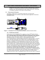
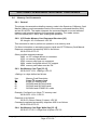
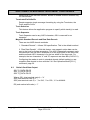
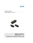
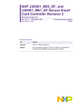
Figure 1 – Orientation for Inserting Card into Reader (Standard chassis shown)
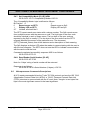
3.4.1. PC/SC Demonstration
Run the demo from the supplied CD by exploring to \demo\SPT3CppPcscDemo
V2.0.1.0\release and double clicking on SPT3CppPcscDemo.exe the icon that looks
like a smart card reader. Note a PC/SC reader must be connected or the program
will report no smart card reader available. If there is a problem, install in the
SPT3CppPcscDemo by double clicking on \Demo\SPT3CppPcscDemo
V2.0.1.0\setup\Setup.exe and following the instructions. Once the demo is installed,
select ‘start’ then ‘all programs’ then ‘IDTECH’ then ‘SPT3CppPcscDemo’ to run
program. If everything is functioning properly the firmware, DLL and driver version
information will display. To demonstrate that the smart card works, fully insert the
provided sample microprocessor card (see card orientation figure above), and then
select ‘Connect Card’. To demonstrate that the card is functional, enter “00 A4 00 00
02 31 40” in the command box, and then select ‘Send APDU’ to card. This will select
file 3140. One should get a “9000” status response from the card. Clear previous
command. To read the first 4 bytes of that file enter “90 52 00 00 04” in the
command box, and then select ‘Send APDU’. You can check the response window
to see the four bytes of response and two bytes of status 90 00. To demonstrate that
the magnetic stripe reading works, select ‘Disconnect’, the message windows will
say “context release successful”. Then select ‘Connect Rdr’ and fully insert a
magnetic stripe card. Select “Get Magstripe Data” button and then within 30 seconds
Copyright 2006-2010 International Technologies & Systems Corp. All rights reserved.
Page 17 of 102
SPECTRUM III HYBRID MAGSTRIPE/SMART CARD READER
pull the card in one clean motion from the reader. The contents of the cards tracks 1,
2 and 3 will display in the response area. To do a quick test of the readers functions
select ‘hardware test’ and following the prompts using the sample microprocessor
card when prompted to insert a valid test card. This verifies that the card seated
switch and the latch are functioning properly. Withdraw the card as prompted to
verify all three magstripe tracks are reading properly. This verifies that smart card
reading and writing are functioning properly and that all three magnetic stripe tracks
are reading properly.2
3.4.2. Non-PC/SC Demonstration
Install the HR_DLL Demo. To do this, in the provided CDROM, double click on the
install program at \Demo\DLL-Demo-V4.1 041124\Setup.exe. Follow the on screen
prompts to install it. There is a document describing this program on the CD-ROM at
\Manuals\HrDLL_Dynamic_Link_Library_454.pdf.
3.5.
FAQ (Frequently Asked Questions)
1. How do I install a Spectrum III reader?
Follow the instructions at QUICK START on page 13
2. When starting the SPT3CppPcscDemo, I get the error message:
Function SCardListReaders returned 0x8010002E error code. No smart
card reader available.
The operating system does not recognize an RS232 smart card reader
attached to it if the PC has not been rebooted since attaching the reader,
reboot the PC and see if the problem goes away. If the reader SPT3s in
PC/SC mode, the PC in may not be in plug and play mode, if the LED is
amber this is the case. See instructions under 11.6 Configuring PC to Support
Serial Plug and Play page 85 for help correcting this situation. If not verify in
the control panel that there is a PC/SC reader attached. If an RS232 reader
was detached and reattached see instructions 11.5 Reconnecting a
Disconnected Reader page 85. If the reader is a USB reader it probably does
not have PC/SC firmware loaded.
3. When starting the SPT3CppPcscDemo program I get the error message:
Function SCardEstablishContext returned 0x8010001D error code.
The Smart card resource manager is not running. See instructions 11.4
configuring the Smart Card Service page 85.
4. When a command is sent to the reader the status code XXXX is
returned, what does this mean?
For a condensed list of reader status codes see – Response Status Code
Summary and Explanation Table page 51. There is a separate document
included with this manual called SPT3_returned_Status.doc. This document
gives a complete list of all the codes returned by the SPT3 with a description
of what the error code means. The SPT3CppPcscDemo will automatically
display these statuses with their meaning. Note the card or driver may return
2
The RS232-PC/SC driver disables the card present switch.
Copyright 2006-2010 International Technologies & Systems Corp. All rights reserved.
Page 18 of 102
SPECTRUM III HYBRID MAGSTRIPE/SMART CARD READER
an error status as well for a list of PC/SC driver error statuses see – SCARD
Error to Value page 60. ICC error statuses can generally be found in ISO7816-4.
5. Does the SPT3 support my card?
The SPT3 supports all T=0 and T=1 microprocessor cards. There is one
reader setting that affects microprocessor cards depending on whether the
particular card supports or conflicts with the EMV specification. If your
microprocessor card fails to work see page 36, the default setting restricts
many cards incompatible with EMV, but that will work fine in a non-EMV
situation. The SPT3 support a wide variety of memory cards, for a summary
list of types of memory cards supported see Memory Card Commands page
47. There is also a separate memory card manual included with this manual
that gives more information on the types of memory cards supported. In the
SPT3CppPscsDemo Changing the default mode of the reader from EMV
cards to ISO cards can be done by selecting the button Configure for ISO
Card. To restore the reader to the original state select Configure for EMV
Card.
6. The LED operation is different from the Sp2, why and how do I make it
the same?
The LED operation is different because some considered the LED distracting
or confusing. The LED can be made to operate like the Sp2 see Set
Compatibility Mode page 38. For a description of how the LED now operates
when controlled by the reader see LED Handling page 23.
Copyright 2006-2010 International Technologies & Systems Corp. All rights reserved.
Page 19 of 102
SPECTRUM III HYBRID MAGSTRIPE/SMART CARD READER
4. PC/SC GENERAL DESCRIPTION
4.1.
Purpose of PC/SC
The purpose of PC/SC is to simplify the integration smart cards and the operating
system. (ID TECH currently only supports PC/SC on Windows 2000 and Windows
XP). It does this by creating a common application interface to smart cards. What
that means is it makes the application independent of reader manufacturer. If one
writes an application to access an ICC in one manufacturers reader then the same
application should be able to access that card though any PC/SC smart card reader.
PC/SC also makes the application somewhat independent of card manufacturer.
PC/SC is not a full solution for a reader that includes features beyond smart cards.
The insufficiencies of PC/SC v1.0 when using a hybrid reader include:
1.
2.
3.
4.
5.
6.
No built in support for Magnetic stripe reading
No built in support for card latching
No built in support for memory cards
Requires a “seated” smart card for normal operation
Access to reader only through the Personal Computer/Smart Card interface
No support for SAM cards.
The supplied IDTLIB.DLL deals with all of these problems and makes interfacing to
these functions seamless to the application.
This reader only supports PC/SC version 1.0. The draft specification for PC/SC
version 2.0 is available but the reader and driver do not support this version at this
time.
4.2.
EMV verses PC/SC
The EMV certification does not require PC/SC and PC/SC certification does not
require EMV to some extent the certifications are incompatible. The purpose of EMV
is to support reliable truly interoperable financial transactions, while PC/SC purpose
is to support easy connection between a PC and smart cards. PC/SC certification
requires support for a range of cards that are incompatible with EMV. To handle this,
the reader has a configuration setting EMV/ISO. A reader configured for EMV (the
default), supports only a subset of the cards supported by the SPT3 reader. A reader
configured for ISO cards may not properly handle certain EMV transactions.
The banking industry generated the EMV specification to provide true interoperability
between a wide variety of smart cards and readers. EMV certification is frequently
required for certified banking applications. EMV is a detailed specification based on
ISO 7816, but EMV is more restrictive and requires extensive certification testing.
Europay, MasterCard, and Visa created this specification and it defines guidelines
for debit and credit transactions. If the financial system, in which the ID TECH reader
is incorporated, requires EMV certification, our reader is EMV level I certified. The
system with the reader incorporated in will have to undergo EMV level II certification.
The certification is to EMV 4.0.
Copyright 2006-2010 International Technologies & Systems Corp. All rights reserved.
Page 20 of 102
SPECTRUM III HYBRID MAGSTRIPE/SMART CARD READER
ISO 7816-3 is a limited specification to which all microprocessor cards are designed.
ISO 7816-3 does not require certification. The purpose of this specification is to
provide microprocessor card access.
4.3.
IdtLib.dll
Purpose of the IdtLib.dll is to simplify access to reader/vendor specific functions like
magnetic stripe reading and latch control in a PC/SC environment. This library is not
required: all functions can be done by the application without this DLL. The purpose
of the supplied DLL is to simplify use of the reader’s features by an application
program.3 It is compatible with the program of the same name provided with the Sp1
and Sp2.
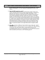
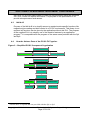
4.4.
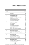
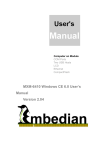
How the Various Parts of the PC/SC Fit Together.
Figure 2 – Simplified PC/SC Component Organization
Vendor Application
IDT DLL (optional)
MFG1 DLL (optional)
MFG2 DLL (optional)
Smart Card Manager
IDT Driver
MFG1 Driver
MFG2 Driver
PnP Manager
BIOS
3
IDT Reader
MFG1 Reader
MFG2 Reader
Smart Card
Smart Card
Smart Card
A newer DLL is required that one provided with the Sp1 or Sp2.
Copyright 2006-2010 International Technologies & Systems Corp. All rights reserved.
Page 21 of 102
SPECTRUM III HYBRID MAGSTRIPE/SMART CARD READER
5. HYBRID READER—GENERAL AND ICC
5.1.
Operation
The ID Tech Hybrid Reader is easy to operate. Make sure the reader is properly
connected and receiving sufficient power. If non-PC/SC reader, the green LED
indicates it is ready to read (if the LED is in reader control mode).
5.1.1. Smart Card Features
Supports 5, 3 and 1.8 Volt T=0 and T=1 microprocessor cards and many memory
cards. The reader has automatic hardware protection for card removal, ESD, supply
voltage drop, and short circuit. This unit reads from and writes information to IC
cards compliant to ISO 7816 standards. The reader communicates depending on
model using a RS232 or USB interface for both ICC and magnetic cards. Landing
style contacts provide for long card life.
5.1.2. Magnetic Card Read Modes
The SPT3 supports two MSR modes.
“Auto Transmit mode” – Reader sends data as soon as the data is available. When
using “Auto Transmit Mode”, the application program needs to be ready to receive
data. Auto Transmit mode is not compatible with ID TECH’s PC/SC drivers.
“Buffered Mode” – The application program first sends an “Arm to Read” command
to enable the magnetic stripe reading. Second, the user inserts and withdraws a
Magstripe card, the decoded data is stored, third the readers notifies the host a
Magstripe read occurred, and MSR is disarmed. The application program then sends
a “Read MSR Data” command to retrieve the data from the buffer. When operating in
PC/SC mode, the reader only supports buffered mode. Do not try to change this.
To read a magnetic stripe card, just follow these simple steps, LED indication
describes LED status change when it is under the control by reader:
5.1.3. Latch Operation
The Latch is an option feature and is not available on every reader. The latch is
locked (latched) and unlocked by command. The latch can be locked only when a
card is fully seated. A card can be forcibly removed without damage to the latch. If
there is a power line voltage failure, the card is automatically unlatched using power
reserves from the capacitors in the power supply output circuits. If the power supply
is not capable of reserve power, an external capacitor must be connected to the
reader PCA. This capacitor is part number 80059215-001. There is a connector on
the PCA for this capacitor when ordered with the option.
Copyright 2006-2010 International Technologies & Systems Corp. All rights reserved.
Page 22 of 102
SPECTRUM III HYBRID MAGSTRIPE/SMART CARD READER
Insert the card, magnetic stripe down, into the reader until it hits a hard stop, (note if
reader is configured for read on insert (the default is on withdrawal) it is important to
insert the card in one continuous motion to insure proper reading of the data). If the
reader is a non-PC/SC reader as soon as it detects data from magnetic stripe, the
green LED indicator will go off.
When the card has been inserted all the way (hits the hard stop), the green LED will
light again if operating in Sp2 LED compatibility mode.
Withdraw the card in one continuous motion. The green LED will go off again. (The
reader is capable of reading a magnetic stripe on both insertion and withdrawal, but
a more reliable read is normally experienced on withdrawal.)
If the reader controls the LED, the LED will turn red (to indicate a bad read) or green
(to indicate a good read) meaning it is ready for another transaction.
Configuring the reader to support auto transmit mode or buffered mode is done with
MSR Transit Mode Setting [53 1A] page 56.
5.1.4. Smart Card Access
To read a smart card, just following these simple steps:
• Insert the smart card into reader as far as it will go. For orientation see figure on
page 17.
• Use smart card commands to communicate with reader after the card has been
inserted all the way.
• See Example T=0 Read [61] and Write [41] Commands to Card page 43.
5.1.5. LED Handling
LED handling can be under the control of the reader or under the control of the host
computer. The default operation is to have the LED under the control of the reader.
• On powering the reader the LED will flash red then green to indicate a successful
start-up.
• For an RS232 reader in PC/SC mode, the LED will turn to amber after power up
until the host plug and play “COM enumerator” detects the reader.
• The LED will flash amber on start-up if the configuration EEPROM has a
problem.
LED handling in reader controlled mode
LED operation depends on whether the reader is in Auto-transmit or Buffer Mode.
Auto-transmit is the default state unless the reader is in PC/SC mode then its default
state is Buffered mode.
Copyright 2006-2010 International Technologies & Systems Corp. All rights reserved.
Page 23 of 102
SPECTRUM III HYBRID MAGSTRIPE/SMART CARD READER
LED handling in buffered mode
o The LED will turn green if the reader is armed to read a magstripe card.
o The LED will turn off if it is not armed to read a magstripe card or has just
read a card.
o The LED will turn red to indicate that the recent magstripe card read was
bad.
LED handling in auto-transmit mode
o The LED will turn green before smart card is powered on or after smart
card has been powered off unless the reader is reading or just read a
Magstripe card.
o The LED will turn off after powering ‘on’ the smart card.
o The Green LED indicates the smart processing is complete and the ICC
powered off. The user can remove the smart card.
LED handling in host controlled mode
If the LED is under the command of the host the following settings are available.
• Turn the LED off
• Turn the LED on Green
• Turn the LED on Red
• Turn the LED on Amber
• Set the LED to Green Flashing
• Set the LED to Red Flashing
• Set the LED to Amber Flashing
• Set the LED to Flashing Red and Amber
Flashing rate is approximately .25 seconds on and .25 seconds off. Regardless on
whether the LED is under the command of the host, the LED will still signal certain
errors and start-up conditions. If configured for RS232 and Plug-and-Play, the LED
will be amber until the reader has sent its plug-and-play string to the host. If there is
a problem on first start-up with configuring the EEPROM the LED will hang flashing
amber.
5.1.6. Lighted bezel option (4 LEDs)
In readers with the lighted bezel option, the 4 LEDs function identically to the single
LED operation as described above and are operated through the Green LED
commands. For example, the command to light the LED green, all 4 LED will
respond with green light simultaneously.
Configuring the reader to support host controlled LED commands is done with 5.4.6
Set Operation Mode [53 11] command, page 36. The host controls the LED with
Host LED Control Command, page 29.
To configure the reader to handle the LED like the SPT2, see 5.4.7 Set Compatibility
Mode page 38.
Copyright 2006-2010 International Technologies & Systems Corp. All rights reserved.
Page 24 of 102
SPECTRUM III HYBRID MAGSTRIPE/SMART CARD READER
5.1.7. Card Status Notification [B0 xx] or [2F 00]
There are six notifications the reader can issue. One is an error notification, the other
five are optional card seated, card unseated notification, optional card present, card
removed notification, and optional buffered magnetic stripe data available.
The reader issues an “error notification” (E0 00 02 2F 00 CD 03), if an IC card was
removed while powered.
The reader can issue a “card notification” (60 00 02 B0 XX YY 03), if “card seated,
card unseated, card present, card removed or buffered magnetic stripe data
available notification” has been set to on and there has been a change to a card is
fully inserted or present, or there is buffered magnetic stripe data available. The
value of XX is the value of the status byte see 5.3.2 Get Reader Status [24] page 28.
Each bit in this byte holds the current status of one piece of information: bit 0—card
powered; bit 1—card seated; bit 2—card latched; bit 3—card present; and bit 4—
magnetic stripe data available.
Configuring the reader to send or not send notifications is done with 5.4.6 Set
Operation Mode [53 11] command, page 36. If the reader is operated in PC/SC
mode does not change the card seated and buffered Magstripe data available
notification settings, because the driver requires these notifications to function
properly.
Copyright 2006-2010 International Technologies & Systems Corp. All rights reserved.
Page 25 of 102
SPECTRUM III HYBRID MAGSTRIPE/SMART CARD READER
5.2.
Communication Structure
This section defines the command format for communicating with the reader.
Turbo TLP-224 Protocol for Sending Commands and Receiving Responses
Command
Response
Reader
Status
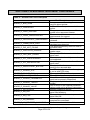
5.2.1. Host Command
All commands originate at the host and expect a response from the reader.
60 <Length> <Command ID> [<Command Data>…] LRC 03
Where:
<Length> = is a two-byte counter from <Command ID> to the end of <Command
Data>.
<Command ID> = is a one byte value identifying a specific command ID, see
command Table 1 – Reader Command ID Summary page 28 and Table 4 – Reader
Command IDs Affecting Smart Card Summary page 39.
<Command Data> = is the data block associated with the command. See details
under each individual command description.
5.2.2. Reader Response
All responses come from the reader in response to a command from the host.
60 <Length> [<Response Data>] <Status> LRC 03
Where:
<Length> = is a two-byte counter from <Response Data> to the end of <Status>.
<Response Data> = is the data block associated with the Response. See details
under each individual command description.
<Status> is a two byte value indicating the success or failure of a command. See
Table 5 – Response Status Code Summary and Explanation page 51.
The overall LRC (Modulus 2 = Exclusive OR) checksum (from 60 to LRC) should be
zero. See 5.2.3 Example of LRC Calculation on page 27.
Copyright 2006-2010 International Technologies & Systems Corp. All rights reserved.
Page 26 of 102
SPECTRUM III HYBRID MAGSTRIPE/SMART CARD READER
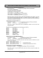
5.2.3. Example of LRC Calculation
Note: SPT3c and SPT3u firmware do not set or check the LRC value, but a place
holder character is required. The USB protocol assures the integrity of the message.
LRC = Longitudinal Redundancy Check. Calculated by taking ‘Exclusive OR’
(Modulus 2) of all characters preceding it, total with LRC is equal to zero.
Example: Calculation of the LRC character
The following memory card command means read 16 bytes of data from
address 0000:
60 00 06 42 DA B0 00 00 10 5E 03
‘5E’ is the LRC character and it is derived as follows:
Characters
60
00
06
42
DA
B0
00
00
10
5E
#1 (binary)
0110
0000
0000
0100
1101
1011
0000
0000
0001
0101
#2 (binary)
0000
0000
0110
0010
1010
0000
0000
0000
0000
1110
Result of Exclusive ‘OR’
5.2.4. Communication Timing
Maximum delay for the reader to respond to a read configuration command is 5 ms.
typical delay is 2 ms.
Maximum delay for the reader to respond to a write configuration command is 20
ms. Typical delay is 5 ms.
During the command processing time, the reader will not respond to a new
command. The reader will accept a new command as soon as it has responded to
the previous command.
Smart card reads and writes timing can very substantially between cards. By the
specifications a smart card may take as long as a minute to complete a command,
so the host application should be prepared to wait 60 seconds before retrying a slow
smart card access command if worst case timings need to be considered.
Note: Maximum delay between two characters in a command is 100ms.
Copyright 2006-2010 International Technologies & Systems Corp. All rights reserved.
Page 27 of 102
SPECTRUM III HYBRID MAGSTRIPE/SMART CARD READER
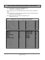
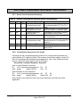
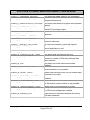
5.3.
General Reader Commands Description
Table 1 – Reader Command ID Summary
ASCII
‘$’
‘8’
Page
28
30
HEX
24
38
Name
Reader Status Report
Copyright Report
‘9’
‘I’
‘L’
‘P’
26
30
42
54
39
49
4C
50
Version Report
Reader Reset
Latching Functions
Arm/Disarm
‘Q’
‘R’
55
51
52
Read Buffered Data
Read Options
53
Set Options
‘S’
‘l’
30
6C
Led Functions
‘z’
30
7A
Enter downloader
Use
Request reader status byte
Requests reader’s copyright
notice
Requests version string
Reset the reader
Latching and Unlatching Card
Arm to Capture Buffer Mode
MSR
Read Stored MSR Data
Read various reader optional
settings
Set various reader optional
functions
Turning on/off/flash the bicolorLED
Upgrading Firmware
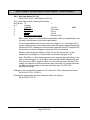
5.3.1. Get Firmware Version Description [39]
60 00 01 39 58 03
Note: An approximately ‘55-byte’ version description will be returned. The description
and length varies somewhat by hardware.
Response is as follows:
60 <Length> <Version Description> LRC 03
Response Example (mixed hex and ASCII):
60 00 31 “ID TECH Spectrum 3 USB Reader v1.00 040802" 0B 03
The 040802 is the date of the firmware version 2 August 2004 (format YYMMDD).
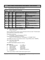
5.3.2. Get Reader Status [24]
60 00 01 24 45 03
The Status byte returned is defined as follows.
Bit Position ‘0’
0
ICC Power not ready
1
Card not seated
2
Latch released
3
Card not present
4
No magnetic data
5~7 Unused all 0
‘1’
ICC Powered
Card seated
Latch closed*
Card present*
Magnetic data present
* Note: flag is always 0 unless reader has the specific option.
Copyright 2006-2010 International Technologies & Systems Corp. All rights reserved.
Page 28 of 102
SPECTRUM III HYBRID MAGSTRIPE/SMART CARD READER
Magnetic data present flag is always 0 if a reader is set in “Auto Mode”.
Response is as follows:
60 00 01 <Reader Status> LRC 03
Response Examples:
60 00 01 00 61 03 no card present
60 00 01 08 69 03 card present
60 00 01 0A 6B 03 card present and seated
60 00 01 0B 6A 03 card present, seated, and powered
60 00 01 0E 6F 03 card present, seated and latched
5.3.3. Latch Close Command [4C 01]
60 00 02 4C 01 2F 03
Use this command to close the latch and entrap the card.
Note: Reader must have the “latch” option on the reader to use this command.
Note: A card must be seated in the reader to close the latch.
Command completed successfully response 9000 is as follows:
60 00 02 90 00 F2 03
Other possible response statuses:
2A00 latch failed to close
2C07 no card seated to latch
6900 latch function subtype must be 0 or 1
6901 reader is not configured with latch hardware
5.3.4. Latch Open Command [4C 00]
60 00 02 4C 00 2E 03
Use this command to release the latch and allow the card to be removed.
Note: Reader must have the “latch” option to support this command.
Command completed successfully response 9000 is as follows:
60 00 02 90 00 F2 03
Other possible response statuses:
2A08 latch failed to open
6900 latch function subtype must be 0 or 1
6902 reader is not configured with a latch
Copyright 2006-2010 International Technologies & Systems Corp. All rights reserved.
Page 29 of 102
SPECTRUM III HYBRID MAGSTRIPE/SMART CARD READER
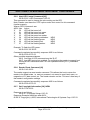
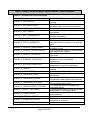
5.3.5. Host LED Control Command [6C]
60 00 02 6C <LED Command> LRC 03
This command is used to change the color setting on the LED.
Note: Reader must have the “LED” option under host control for this command
function properly.
Where <LED Command> are:
ASCII Hex Action
‘0’
30
LED will be turned off.
‘1’
31
LED will be turned on green.
‘2’
32
LED will be turned on red.
‘3’
33
LED will be turned on amber.
‘4’
34
LED will be flashing red/amber. NEW
‘5’
35
LED will be flashing green.
NEW
‘6’
36
LED will be flashing red.
NEW
‘7’
37
LED will be flashing amber.
NEW
Example: To flash the LED green:
60 00 02 6C 35 3B 03
Command completed successfully response 9000 is as follows:
60 00 02 90 00 F2 03
Other possible response statuses:
6913 2nd byte of LED command must be 30-37
691F host LED control not enabled. To configuring the reader to support host
controlled LED commands see 5.4.6 Set Operation Mode [53 11] command,
page 36.
5.3.6. Reader Reset Command [49]
60 00 01 49 28 03
The reader supports a reset reader command. This allows the host to return the
reader to its default state, i.e. card not powered, not armed to read, latch open, no
magnetic or ICC data stored, etc. The reader remains on-line. This won’t reset any of
the readers’ configuration settings.
Command completed successfully response 9000 is as follows:
60 00 02 90 00 F2 03
5.3.7. Get Copyright Information [38] NEW
60 00 01 38 59 03
Response is as follows:
60 00 3F <Copyright String> LRC 03
Response Example mixed hex and ASCII:
60 00 3F Copyright (c) 2005, International Technologies & Systems Corp. LRC 03
Copyright 2006-2010 International Technologies & Systems Corp. All rights reserved.
Page 30 of 102
SPECTRUM III HYBRID MAGSTRIPE/SMART CARD READER
5.3.8. Enter Downloader (Upgrade Firmware) [7A] NEW
60 00 01 7A 1B 03
If the reader is able to enter the downloader it flashes the LED red, green, dark and
acknowledges the command. The reader is then ready to receive download
commands typically for firmware upgrading. See Download Manual first.
Command completed successfully response 9000 is as follows:
60 00 02 90 00 F2 03 or
691D download code missing or corrupt.
5.4.
Reader Configuration Commands Description
5.4.1. Restore Configuration Settings to Default [53 18]
60 00 02 53 18 29 03
This command restores most settings to their default value. See Table 2 –
Default MSR Configuration Settings page 31, for default values. Note:
Executing this command does not affect the operations mode (page 36), or
the serial number.
Command completed successfully response 9000 is as follows:
60 00 02 90 00 F2 03
Default Configuration Settings
Table 2 – Default MSR Configuration Settings
SETTING
MSR Reading
Magnetic Decoding Method
Send Option
Terminator Settings
Prefix Setting
Suffix Setting
Track Selected Settings
Track Separator Settings
Baud Rate Setting
X-On Character Setting
X-Off Character Setting
Track 1 ID
Track 2 ID
Track 3 ID
Operations Mode
DEFAULT
Enabled Auto Mode*
Withdraw Only
Send Start/end Sentinel
CR (Hex OD)
None
None
Any Track
CR (Hex OD)
38400 bps
DC1 (Hex 11) unused
DC3 (Hex 13) unused
None
None
None
MSR Enveloped, MSR data present
notification off*, Standard Decoder
IC Card Type
5V Microprocessor Card
Memory IC Card Type
Type 0 3-byte I2C Card
*PC/SC driver changes this to Buffered Mode & magstripe data notification on.
Copyright 2006-2010 International Technologies & Systems Corp. All rights reserved.
Page 31 of 102
SPECTRUM III HYBRID MAGSTRIPE/SMART CARD READER
5.4.2. Read All Configuration Settings [52 1F]
60 00 02 52 1F 2F 03
This command does not have any <FuncData>. It retrieves all current
settings. The Spectrum 3 reader sends back an <ACK> and <Response>.
<Response> format:
The current configuration data block is a collection of many Function-Setting
blocks <FuncSETBLOCK> as follows:
60 <Length> <FuncSETBLOCK1>…<FuncSETBLOCKn> LRC 03
Each Function-Setting block <FuncSETBLOCK> has the following format:
<FuncID> <Len> <FuncData>
Where:
<Length> is a two bytes counter, which indicates bytes of all
<FuncSETBLOCK>. The most significant byte comes first.
<FuncID> is a one byte Function ID identifies the setting(s) for the function.
For a complete list of FuncID see Table 3 – Configuration Function ID
Summary and Explanation page 33.
<Len> is a one-byte length count for the following function-setting block
<FuncData>.
<FuncData> is the current setting for this function. It has the same format as
in the Sending Command for this function. See SENDING COMMAND
LIST for details.
<FuncSETBLOCK> are in the order of their function ID <FuncID>.
Example:
60 00 51 10 01 00 11 01 0E 12 01 00 13 01 30 17 01 0D 19
01 31 1A 01 31 1D 01 33 1B 01 B8 21 01 31 41 01 37 47 01
11 48 01 13 31 01 00 32 01 00 33 01 00 61 02 C0 00 62 02
80 00 63 02 00 00 64 02 00 00 65 02 00 00 D2 01 00 D3 01
00 1C 02 BF 01 1E 01 00 5D 03
Example Interpreted:
60 00 51
ACK, length data: 0051 hex or 81 decimal.
10 01 00
10=card option—page 31, length 1, value 00
11 01 0E
11=operation mode—page 36, length 1, value 0E
12 01 00
12=memory card type—page 47, length 1, value 00
...
61 02 00 00 6n = Set SAM card option, See page 50, length 2, value 00 00
...
5D 03
LRC, ETX.
Copyright 2006-2010 International Technologies & Systems Corp. All rights reserved.
Page 32 of 102
SPECTRUM III HYBRID MAGSTRIPE/SMART CARD READER
5.4.3. Read Specific Configuration Setting [52 nn]
60 00 02 52 <Configuration> LRC 03
The <Configuration> byte corresponds to the byte from a specific configuration
value.
All MSR reader Read Configuration Commands are listed in the following format:
60 00 02 52 <FuncID> LRC 03
For example to read the “Card Option” configuration send
60 00 02 52 10 20 03
Table 3 – Configuration Function ID Summary and Explanation
Function Description
IC Card Option
Set Operation Mode
Memory IC Card Type
Track Selected Settings
Track Separator Settings
Send Option
MSR Reading
Data Editing
Magnetic Decoding Method
Terminator Settings
Track 1 ID
Track 2 ID
Track 3 ID
Baud Rate Setting
X-On ID
X-Off ID
Connector 0 setting
SAM 1 setting
SAM 2 setting
SAM 3 setting
SAM 4 setting
SAM 5 setting
Prefix Setting
Suffix Setting
Compatibility mode
Reader serial number
Memory card page size
Function ID
10
11
12
13
17
19
1A
1B
1D
21
31
32
33
41
47
48
60
61
62
63
64
65
D2
D3
1E
4E
15
Function Value
Any Value
Any Value
00 – 07H
‘0’ – ‘7’
Any ASCII Code
‘0’ – ‘3’
‘0’ – ‘2’
Not Used
‘1’ – ‘3’
CR/LF, CR, LF, None
Any ASCII Code
Any ASCII Code
Any ASCII Code
‘5’ – ‘9’
Not Used
Not Used
Any Value
Any Value
Any Value
Any Value
Any Value
Any Value
String
String
00 – 07H
8 Digits
8, 16, 32, 64 or 128
Page
31
36
47
58
58
56
56
56
56
57
57
57
34
50
50
50
50
50
50
57
57
38
31
47
Copyright 2006-2010 International Technologies & Systems Corp. All rights reserved.
Page 33 of 102
SPECTRUM III HYBRID MAGSTRIPE/SMART CARD READER
5.4.4. Set BAUD Rate [53 41] (RS232 only)
The RS232 interface has several programmable features so the SPT3s can
be optimized for the user’s application. These settings can be made through a
basic set up defined in the following sections.
Note: A SPT3s operated in PC/SC mode must leave BAUD rate at the default
because the driver only supports the default BAUD rate.
Note: Default settings are in bold and underlined
Baud-Rate
Data-Bits
Parity
Stop Bits
Hand-Shaking
9.6K, 19.2K, 38.4K, 57.6K and
115.2K
8
None
1
hardware
The hybrid reader will set itself to operate at the last configured BAUD rate;
the default is 38.4K bits/sec after power up. After connecting the application
can choose from 9.6K, 19.2K, 38.4K, 57.6K and 115.2K bits/sec. Reader will
turn to the set BAUD rate after sending the response to this set command.
Application should turn to the new BAUD rate after receiving the response to
ensure the communication between application and hybrid reader.
Set host to reader BAUD Rate Command
60 00 04 53 41 01 <BAUD Rate Setting> LRC 03
The <BAUD Rate Setting> byte is defined below:
ASCII Hex BAUD Rate
‘5’
35
9600 bits/sec
‘6’
36
19.2K bits/sec
‘7’
37
38.4K bits/sec
‘8’
38
56.7K bits/sec
‘9’
39
115.2K bits/sec
All other values are reserved.
Example to set baud rate to 115.2K BAUD
60 00 04 53 41 01 39 4E 03
Command completed successfully response 9000 is as follows:
60 00 02 90 00 F2 03
Copyright 2006-2010 International Technologies & Systems Corp. All rights reserved.
Page 34 of 102
SPECTRUM III HYBRID MAGSTRIPE/SMART CARD READER
5.4.5. Set Card Option [53 10]
60 00 04 53 10 01 <Card Option> LRC 03
The <Card Option> byte is defined as follows.
Bit Position ‘0’
0~2
Unused
3
1.8V Off
4
EMV Card
5
3V Off
6
5V On
7
Microprocessor Card
‘1’
1.8V On
ISO Card
3V On
5V Off
Memory Card
NEW
EMV card is subject to all the checks described on EMV 4.0 specification, and
the card communication follows the specification.
For a microprocessor card if more than one voltage is ‘on’, the reader will try
lowest voltage first then next higher and finally the highest when attempting to
retrieve the ATR. Subsequent communication between the SPT3 and the ICC
will continue to use the voltage at which the ATR was retrieved.
Memory card handling is different if both 3V and 5V options are ‘on’ the
reader will only attempt to communicate at the lowest voltage i.e. 3V.
Note: The EMV vs. ISO setting may have to be properly set depending on the
type of card accessed. If it is an EMV card involved in EMV transactions then
it must be set to EMV. However, EMV is more restrictive than ISO and if the
reader is configured to EMV mode then many cards will not function because
the EMV forces the reader to be more restrictive than the ISO 7816
specification allows.
Example to set configuration access an ICC card at 5V, ISO, microprocessor card
60 00 04 53 10 01 10 36 03
Command completed successfully response 9000 is as follows:
60 00 02 90 00 F2 03
Copyright 2006-2010 International Technologies & Systems Corp. All rights reserved.
Page 35 of 102
SPECTRUM III HYBRID MAGSTRIPE/SMART CARD READER
5.4.6. Set Operation Mode [53 11]
60 00 04 53 11 01 <Operation Mode> LRC 03
The <Operation Mode> byte is defined as follows.
Bit Position ‘0’
‘1’
0
PC/SC mode Off
PC/SC Mode On
1
Card Seated Change Off
Card Seated Change On
2
Card Present Change Off
Card Present Change On
3
MSR Data Envelop Off
MSR Data Envelop On
4
LED Controlled by reader
LED Controlled by Host
5
Magnetic data present off
Magnetic data present on
(default if PC/SC)
6
Standard decoder
Raw magnetic data decoder
7
Unused
For the SPT3s, PC/SC Mode On sets the reader to “Plug and Play.” All USB readers
ignore this setting, as they are always plug-and-play, but in a USB reader plug-andplay does not force to PC/SC mode. For details see Plug and Play Support (RS232
only) page 37.
For any reader operating in PC/SC mode do not change bits 1, 3 and 5 as the driver
depends on these bits being on to function properly, the PC/SC driver checks and
sets these bit as required when the reader first connects to the driver.
If “Raw data decoder” has been set, the reader treats all magstripe data as a bit
string and sends it out in hex format. The reader suppresses leading and trailing
zeros. All the read tracks data is sent with no regard to track designation or
separation. No error checking is performed.
Note: The reader only reports magnetic data present notification when set to
buffered mode.
A “Status change notification” (60 00 02 B0 <Card Status> LRC 03) is issued by the
reader, if “Card Seated Change” or “Card Present Change” has been set on and
card switch changed.
If the LED control bit is changed to host control, the LED is turned off.
After a good read, Magstripe data will be sent out enveloped (60 <Len_H> <Len_L>
<Card data indication 1> <Card indication 2> <Magstripe data> LRC 03), if “MSR
Data Envelop” is on, Otherwise magstripe will be sent out without an envelop <Card
data indication 1> <Card indication 2> <Magstripe Data>). In PC/SC mode the
Magstripe data is always enveloped.
<Card data indication 1> (<C0>) identifies a response as magnetic data.
<Card data indication 2> is flags about current read.
Copyright 2006-2010 International Technologies & Systems Corp. All rights reserved.
Page 36 of 102
SPECTRUM III HYBRID MAGSTRIPE/SMART CARD READER
Bit Position
0
1
2
3
4
5
6~7
‘0’
Track 1 decode fail
Track 2 decode fail
Track 3 decode fail
No Track 1 data
No Track 2 data
No Track 3 data
Unused
‘1’
Track 1 decode success
Track 2 decode success
Track 3 decode success
Track 1 data exists
Track 2 data exists
Track 3 data exists
Note: Track 1, 2, or 3 decode flag is 0 if the track does not exist.
Note: The Operation Mode configuration byte is unchanged when the reader’s
configuration is reset to its default setting. The default setting as shipped from the
factory is 0FH.
Command completed successfully response 9000 is as follows:
60 00 02 90 00 F2 03
Plug and Play Support (RS232 only)
Reader will notify the operating system of its arrival by sending “Device ID String” at
1200 baud (1200, 7, 1, Mark), after the reader is power up or reconnected to the PC.
The reader will only send this string if the operating system requests it. The
operating system will only request the PnP string on boot and on scanning for
hardware changes. To set an RS232 reader to PC/SC mode configure it for plugand-play.
Plug-and-Play Device ID String:
(<01 22>ITS0020\[Serial Number]\\\ID TECH 0030 Hybrid Mag&EMV Card Reader
[Check Sum byte 1][Check Sum byte 2])
[Serial Number] is an 8-byte string, represents serial number of a device.
[Check Sum byte 1] and [Checks Sum byte 2] are single byte check characters.
To change the reader from the default setting of PnP or to restore the PnP setting,
see Section 5.4.6 Set Operation Mode [53 11] page 36.
Copyright 2006-2010 International Technologies & Systems Corp. All rights reserved.
Page 37 of 102
SPECTRUM III HYBRID MAGSTRIPE/SMART CARD READER
5.4.7. Set Compatibility Mode [53 1E] NEW
60 00 04 53 1E 01 <Compatibility Mode> LRC 03
The <Compatibility Mode> byte is defined as follows.
Bit Position ‘0’
‘1’
0
Report errors as SPT3
Report errors as Sp2
1
Display LED as SPT3
Display LED as Sp2
2-7
Unused, all should be 0
The SPT3 reports each error status with a unique number. The Sp2 reports errors
from multiple sources with the same error code. The high byte of the error code
should be identical in each of these cases. The low byte of the error code as
reported by the Sp2 is usually 0. The low byte of the error code from the SPT3
uniquely identifies the source of the particular error. The document
(SPT3_Returned_Status) lists all the statuses and a description of their meaning.
The Sp2 displays an Amber LED when the reader is communicating with the card or
with the host computer. The SPT3 does not use the LED to indicate communication
with the card or with the host.
Command completed successfully response 9000 is as follows:
60 00 02 90 00 F2 03
5.4.8. Read Reader Serial Number [52 4E]
60 00 02 52 4E 7E 03
Note: An ‘8-byte’ string of serial number will be returned.
Response is as follows:
60 00 0B 4E 09 08 <Serial Number (8 bytes)> LRC 03
5.5.
Microprocessor Commands Descriptions
All ICC reader commands follow the Turbo TLP-224 protocol and use the ISO 78164 Application Protocol Data Unit (APDU) or 7816-3 Transport Protocol Data Unit
(TPDU) structure to communicate with the IC card. Note: <length> is two bytes first
byte is the most significant second is the least significant.
Copyright 2006-2010 International Technologies & Systems Corp. All rights reserved.
Page 38 of 102
SPECTRUM III HYBRID MAGSTRIPE/SMART CARD READER
5.5.1. Smart Card Commands Summary
Table 4 – Reader Command IDs Affecting Smart Card Summary
ASCII
‘A’
Hex
41
Page
39
Name
Output to a T=0 or T=1
microprocessor card
‘a’
61
43
‘B’
42
47
‘C’
43
49
Input from T=0 or T=1
microprocessor card
Communicate with
memory card
Select ICC connector
‘F’
46
44
Raw T=1 I/O with
microprocessor card
‘M’
‘n’
4D
6E
41
39
ICC Power OFF
ICC Power ON
Use
Write command (may include data)
to a microprocessor (T=0 or T=1)
card
Read command to microprocessor
card and waits for response data
Command for accessing, reading
and writing memory cards
Switches between User and SAM
ICC connectors
Sends command to T=1 card &
awaits response, host handles T=1
protocol.
Power off ICC card
Power on microprocessor card,
return ATR
5.5.2. Transmission Protocol for ICC Cards
Following are the command/response protocols for communication between the
hybrid reader (ICC media) and host. The protocol used by this reader is turbo TLP224. All commands and characters are presented in ‘Hex’. Note: Maximum buffer
size for read is 256 bytes and for write is 255 bytes.
Successful Command Response Sequence
Host to Hybrid Reader Command
60
LH LL nnnnnnnnnnnnnnnnnnnn ZZ
03
ACK length
data(C-APDU)
LRC 03
Hybrid Reader to Host Response
60
LH LL nnnnnnnnnnnnnnnnnnnn SS
ZZ
ACK length
data(R-APDU)
Status LRC
03
03
Note: length is two bytes first byte is the most significant, second is the least
significant.
Copyright 2006-2010 International Technologies & Systems Corp. All rights reserved.
Page 39 of 102
SPECTRUM III HYBRID MAGSTRIPE/SMART CARD READER
Unsuccessful Command Response Sequence
Host to Hybrid Reader Command
60
LH LL nnnnnnnnnnnnnnnnnnnn ZZ
03
ACK length
data(C-APDU)
LRC 03
Hybrid Reader to Host Response
E0
LH LL nnnnnnnnnnnnnnnnnnnn SS
ZZ
NACK length
data(R-APDU)
Status LRC
Or
E0
LH LL SS
NACK length
ZZ
03
Status LRC
03
03
03
The status either defines a successful transaction or gives an error code (see Table
5 – Response Status Code Summary and Explanation page 51).
5.5.3. Power On (Get ATR) Command [6E]
60 00 <Length> 6E [<Option>] [<PPS>] LRC 03
This command is used to power up the currently selected microprocessor card. It
follows the ISO7816-3 power up sequence and returns the ATR as its response.
Memory cards do not have an explicit power up command, i.e. any I/O operation
sent to the card causes a power up.
<Option> and <PPS> are optional, but <Option> must be present if <PPS> is used.
Note: The <Option> byte is defined as follows.
Bit
‘0’
‘1’
Position
No IFS
0
Send S(IFS) request if T=1 protocol
1
No Explicit PPS
Explicit PPS
2-5
Unused (all 0)
Auto PPS
6
No auto PPS for negotiable mode
IFS response check
7
No check on response of S(IFS) request
<PPS> is to set the Protocol and Parameters Selection between card and reader,
only Di <= 4 are supported. PPS must follow the structure specified in ISO 7816-3 as
PPS0, [PPS1], [PPS2], and [PPS3]. Typically the <PPS> is two bytes long. For more
information see ISO 7816-3 section 7.2.
Example:
60 00 04 6E 02 10 11 09 03
Where 02 is the <Option> 10 is PPS0 and 11 is PPS1
Response is as follows:
60 00 <ATR Length> <ATR string> LRC 03
Example:
60 00 15 3B 6F 00 00 80 25 A0 00 00 00 68 54 08 00 0B 00
82 90 00 90 00 99 03
Copyright 2006-2010 International Technologies & Systems Corp. All rights reserved.
Page 40 of 102
SPECTRUM III HYBRID MAGSTRIPE/SMART CARD READER
Other possible response statuses:
2C06 no card seated to request ATR
2D01 Card Not Supported,
2D03 Card Not Supported, wants CRC
690D command not supported on reader without ICC support
8100 ICC error time out on power-up
8200 invalid TS character received
8500 PPS confirmation error
8600 Unsupported F, D, or combination of F and D
8700 protocol not supported EMV TD1 out of range
8800 power not at proper level
8900 ATR length too long
8B01 EMV invalid TA1 byte value*
8B02 EMV TB1 required*
8B03 EMV Unsupported TB1 only 00 allowed*
8B04 EMV Card Error, invalid BWI or CWI*
8B06 EMV TB2 not allowed in ATR*
8B07 EMV TC2 out of range*
8B08 EMV TC2 out of range*
8B09 per EMV96 TA3 must be > 0xF*
8B10 ICC error on power-up
8B11 if EMV96 T=1 then TB3 required*
8B12 Card Error, invalid BWI or CWI
8B13 Card Error, invalid BWI or CWI
8B17 EMV TC1/TB3 conflict*
8B20 EMV TD2 out of range must be T=1*
8C00 TCK error
A304 connector has no voltage setting
A305 ICC error on power-up invalid (SBLK(IFSD) exchange
E301 ICC error after session start
*Connector is configured for EMV, but ICC is not a valid EMV ICC. To support this
card in this connector change the configuration from EMV to ISO see 5.4.5 Set Card
option [53 10] page 35. If connector is a SAM connector also see 5.7.4 Set SAM
Card Option [53 6n 02] on page 50.
Please refer to Appendix C for the complete list of response codes.
Copyright 2006-2010 International Technologies & Systems Corp. All rights reserved.
Page 41 of 102
SPECTRUM III HYBRID MAGSTRIPE/SMART CARD READER
Power Off Command [4D]
60 00 01 4D 2C 03
This command is used to power down the current selected card. It works for both
microprocessor and memory cards.
Note: If powering off an ICC in a SAM connector be aware all SAM connectors will
be powered off.
Command completed successfully response 9000 is as follows:
60 00 02 90 00 F2 03
Other possible response statuses:
6907 command not supported on reader without ICC support
5.5.4. ICC Reader Microprocessor Card Output Command Structure [41]
60 <length> 41 <APDU> LRC 03
This 41 command is used to pass a T=0 write or any T=1 APDU to a
microprocessor card where for a T=0 card only an ISO status is expected.
See Example T=0 Read [61] and Write [41] Commands to Card page 43.
See Example T=1 Read and Write Commands to Card [41] page 42
Possible response statuses:
2C02 no microprocessor ICC seated
6903 reader configured without ICC support
9000 Success
Example T=1 Read and Write Commands to Card [41]
IBM PC/SC T=1 test card example (Card available from PC/SC workgroup).
Start the IDTECH PC/SC Sample demo program insert the IBM PC/SC T=1 card in
the reader.
In the command window type the following commands in hex:
Command to set Card type as 5V, EMV, microprocessor card
60 00 04 53 10 01 00 26 03
Response completed successfully 9000 is as follows:
60 00 02 90 00 F2 03
Command to request ATR
60 00 02 6E 01 0D 03
ATR response should be
60 00 1A 3B EF 00 FF 81 31 86 45 49 42 4D 20 4D 46 43 34
30 30 30 30 38 33 31 43 90 00 D1 03
Command to Select File 0007
60 00 08 41 A4 A4 00 00 02 00 07 2C 03
Copyright 2006-2010 International Technologies & Systems Corp. All rights reserved.
Page 42 of 102
SPECTRUM III HYBRID MAGSTRIPE/SMART CARD READER
Response should be
60 00 10 63 0C 03 E8 00 07 00 00 00 FF FF 11 01 00 90
00 73 03
Write File 5 bytes from 0000
60 00 0B 41 A4 D6 00 00 40 00 01 02 03 04 1C 03
Response completed successfully 9000 is as follows:
60 00 02 90 00 F2 03
Read File 05 bytes from 0000
60 00 06 41 A4 B0 00 00 05 36 03
Response from the reader should be
60 00 07 00 01 02 03 04 90 00 F3 03
Command to power off the ICC
60 00 01 4D 2C 03
Response completed successfully 9000 is as follows:
60 00 02 90 00 F2 03
5.5.5. ICC Reader Microprocessor Card Input Command Structure [61]
60 <length> 61 <APDU> LRC 03
This 61 command is used to pass a T=0 read or any T=1 APDU to a microprocessor
card where both data and an ISO status are expected from card.
See Example T=0 Read [61] and Write [41] Commands to Card page 43.
See Example T=1 Read and Write Commands to Card [41] page 42
Possible response statuses:
2C02 no microprocessor ICC seated
6903 reader configured without ICC support
9000 Success
Example T=0 Read [61] and Write [41] Commands to Card
If you use the ID TECH provided sample card labeled Microprocessor – 1K Byte
P/N: 80005206-001. (If the reader has not been installed follow the installation
procedure in section 3 QUICK START page 13).
Start the ID TECH PC/SC Sample demo program insert the T=0 sample card in the
reader.
In the command window type the following commands in hex: In each of the
examples the underlined portion of the command is the part that is entered. The rest
of the command is the envelope, which is added automatically by the demo program.
Select File 3040
41 00 A4 00 00 02 30 40
Response completed successfully 9000 is as follows:
60 00 02 90 00 F2 03
Copyright 2006-2010 International Technologies & Systems Corp. All rights reserved.
Page 43 of 102
SPECTRUM III HYBRID MAGSTRIPE/SMART CARD READER
Verify CHV (samplepassword)
60 00 14 41 00 20 00 80 0E 73 61 6D 70 6C 65 70 61 73
73 77 6F 72 64 LRC 03
Response completed successfully 9000 is as follows:
60 00 02 90 00 F2 03
Write 8 bytes 12345678 to file 3040 address 0000
60 00 0E 41 00 D6 00 00 08 31 32 33 34 35 36 37 38 F9 03
Response completed successfully 9000 is as follows:
60 00 02 90 00 F2 03
Read 8 bytes from address 0000
60 00 06 61 00 B0 00 00 08 BF 03
Response should be
60 00 0A 31 32 33 34 35 36 37 38 90 00 F2 03
Write 8 bytes ABCDEFGH to address 0000
60 00 0E 41 00 D6 00 00 08 41 42 43 44 45 46 47 48 LRC 03
Response completed successfully 9000 is as follows:
60 00 02 90 00 F2 03
Read 8 bytes from address 0000
60 00 06 61 00 B0 00 00 08 BF 03
Response should be ABCDEFGH
60 00 0A 41 42 43 44 45 46 47 48 90 00 F2 03
5.5.6. ICC Reader Microprocessor Card Raw T=1 Command Structure [46]
60 <length> 46 <NAD> <PCB> <LEN> <INF> <EDC> LRC 03
This command is used to pass a T=1 data block to a microprocessor card.
See Example T=1 Raw Read and Write Commands to Card page 45.
Response completed successfully 9000 is as follows:
60 00 02 90 00 F2 03
Possible response statuses:
2C04 no T=1 raw card seated
6906 reader configured without ICC support
9000 Success
Copyright 2006-2010 International Technologies & Systems Corp. All rights reserved.
Page 44 of 102
SPECTRUM III HYBRID MAGSTRIPE/SMART CARD READER
Example T=1 Raw Read and Write Commands to Card
This sample uses the IBM PC/SC T=1 Test Card (Card available from PC/SC
workgroup).
Negotiate IFS (Propose maximum block size of 254 bytes).
60 00 06 46 00 C1 01 FE 3E LRC 03
Response
60 00 05 00 E1 01 FE 1E LRC 03
Select file 0007
60 00 0C 46 00 00 07 A4 A4 00 00 02 00 07 02 LRC 03
Response
60 00 14 00 00 10 63 0C 03 E8 00 07 00 00 00 FF FF 11 01
00 90 00 13 LRC 03
Write 1 byte to file at address 0000
60 00 0B 46 00 40 06 A4 D6 00 00 01 00 35 LRC 03
Response
60 00 06 00 40 02 90 00 D2 LRC 03
Read 1 byte from file starting at address 0000
60 00 0A 46 00 00 05 A4 B0 00 00 01 10 LRC 03
Response
60 00 07 00 00 03 00 90 00 93 LRC 03
Write 25 bytes to address 0000
60 00 23 46 00 40 1E A4 D6 00 00 19 00 01 02 03 04 05 06
07 08 09 0A 0B 0C 0D 0E 0F 10 11 12 13 14 15 16 17 18 2D
LRC 03
Response
60 00 06 00 40 02 90 00 D2 LRC 03
Read 19H (25 decimal) bytes starting at address 0000
60 00 0A 46 00 00 05 A4 B0 00 00 19 08 LRC 03
Response
60 00 1F 00 00 1B 00 01 02 03 04 05 06 07 08 09 0A 0B 0C
0D 0E 0F 10 11 12 13 14 15 16 17 18 90 00 93 LRC 03
Copyright 2006-2010 International Technologies & Systems Corp. All rights reserved.
Page 45 of 102
SPECTRUM III HYBRID MAGSTRIPE/SMART CARD READER
5.5.7. ISO 7816 Command Structure
CLA INS P1 P2 [Lc] [Data] [Le]
ISO 7816-3 Command Structure:
CLA INS P1 P2 P3 (Lc or Le) Data (if P3 is Lc)
Definition of Commands:
<CLA> ISO Class byte
<INS> ISO instruction code
<P1> ISO Parameter 1, usage varies with commands
<P2> ISO Parameter 2, usage varies with commands
<Lc> The number of bytes present in the data field of the command APDU
<Le> The maximum number of bytes expected in the data field of the response
APDU.
<P3> ISO Parameter 3, length of data Lc or maximum length of expected reply Le
<Data> Data to send, varies with commands
<NAD> ISO Node Address always 0 for T=1 protocol
<PCB> ISO Protocol Control Byte for T=1 protocol
<LEN> Length byte for T=1 protocol
<INF> Information field for T=1 protocol
<EDC> Error detection code of the block, only LRC is supported.
Response Structure:
<Data>(Optional)<SW1> <SW2>
<Data>
<SW1>
<SW2>
Response data usually Le bytes if operation was successful
Status byte 1
Status byte 2
Copyright 2006-2010 International Technologies & Systems Corp. All rights reserved.
Page 46 of 102
SPECTRUM III HYBRID MAGSTRIPE/SMART CARD READER
5.6.
Memory Card Commands
5.6.1. General
The primary documentation detailing memory cards is the Spectrum III Memory Card
Manual. Memory card commands consist of the memory command identifier (42H)
and an ISO APDU. The reader interprets the command based on current selected
memory card type and performs the requested operation. The reader returns
ISO7816 status (SW1, SW2) after finishing the operation.
5.6.2. ICC Reader Memory Card Command Structure [42]
60 <length> 42 <Command> LRC 03
This command is used to perform an operation on a memory card.
For More information on accessing memory cards see SPT3 Memory Card Manual.
Response completed successfully 9000 is as follows:
60 00 02 90 00 F2 03
Other possible response statuses:
2A06 no ICC voltage defined on connector
2C03 no memory card seated
2D00 memory card type not supported
6904 reader configured without ICC support
6E00 memory card class must be 'DA'
5.6.3. Set Memory Card Type [53 12]
60 00 04 53 12 01 <Setting> LRC 03
<Setting> is a byte defined as follows.
Hex
00
01
02
03
06
Memory Card Description
3-byte I2C memory card
4-byte I2C memory card
SLE4428 and SLE4418 cards
SLE4442 and SLE4432 cards
SLE4404 and AT88SC101 cards
Example: Configure for a 4-byte I2C memory card
60 00 04 53 12 01 01 25 03
Response is as follows:
60 00 02 <Return Status (2 bytes)> LRC 03
Command completed successfully response 9000 is as follows:
60 00 02 90 00 F2 03
5.6.4. Set Memory Card Page Write Size [53 15]
60 00 0C 53 15 01 <Page Size in Bytes> LRC 03
Copyright 2006-2010 International Technologies & Systems Corp. All rights reserved.
Page 47 of 102
SPECTRUM III HYBRID MAGSTRIPE/SMART CARD READER
Page Size is a one byte value indicating the page size for the memory card. Only
memory cards types zero and one use this feature. The default value of 8 will work
for all supported cards. If performance of the write to card becomes a problem when
writing larger blocks of data, setting this value correctly will increase performance.
Card Size in
Chip Type
Memory Card Type Page Size
Bytes
AT24C01A
0
8
128
AT24C02
0
8
256
AT24C04
0
16 (10H)
512
AT24C08
0
16 (10H)
1024
AT24C16
0
16 (10H)
2048
AT24C64
1
32 (20H)
8192
AT24C128
1
64 (40H)
16384
AT24C256
1
64 (40H)
32768
AT24C512
1
128 (80H)
65536
Command to set the page size to 32 bytes for the type 1 AT24C64 card.
60 00 04 53 15 01 20 03 03
Command completed successfully response 9000 is as follows:
60 00 02 90 00 F2 03
5.7.
SAM—Secure Access Module Support
5.7.1. SAM Purpose
SAM is a smart card in a smaller form factor, that provides authentication and or
encryption support for a particular card type. They fit into either one SIM connector
on the PCA or into up to five SIM connectors on an expansion board that attaches to
the reader. If a reader is set up to support only one type of card then the reader will
probably only need one SAM card. If a reader is configured to accept a variety of
cards e.g. Visa, MasterCard and Discover (electronic purse/cash cards) it may need
a SAM card for each card type that it supports.
5.7.2. Typical SAM Operation
Note: Because PC/SC v1.0 only can handle one card at a time, SAM access should
be done without the PC/SC interface. This is necessary because when Windows
Smart Card Manager talks to an ICC it controls the sequence numbering, chaining,
etc. so it will become confused if attempting to talk to a second ICC before the
session with the first ICC is closed.
In typical operation the host will ask the users card for a random number, which is
then given to the SAM card. The SAM card will then generate an encoded message
containing a secret key, which is presented to the user card. The user card will
generate a response, which is given to the SAM card, which will then inform the host
of the user's card validity.
Many types of smart card applications require additional security/fraud protection.
Copyright 2006-2010 International Technologies & Systems Corp. All rights reserved.
Page 48 of 102
SPECTRUM III HYBRID MAGSTRIPE/SMART CARD READER
One such method for insuring secure transactions is the use of a “Secure Application
Module” (SAM). The SAM is a miniature smart card (it is slightly larger than the
contact pads on a standard smart card) that contains security algorithms, and
provides a secure place to store keys. ID TECH insert readers can optionally provide
for up to five (5) independent SAM connectors, one is located on the main printed
circuit board (PCA), or up to five are located on a separate PCA that is secured to
the main PCA. The quantity required depends upon the customer’s application(s).
ID TECH’s family of EMV smart card and hybrid insert reader/writers can support up
to 6 smart card connectors (5 SAM & 1 smart card connector). When addressing the
connectors, the main (smart card) connector is assigned the number ‘0’, and each of
the SAM modules is assigned a number from 1 to 5. If the SAM daughter board is
used do not use the SAM connector on the main PCA because it is inaccessible and
it has the same address as a connector on the SAM board so there would be a
conflict.
5.7.3. ICC Connector Selection [43 0n]
60 00 02 43 <Card Connector> LRC 03
<Card Connector> is a byte defined as follows.
Hex
00
01
02
03
04
05
Connector Description
User Card Connector (main module)
SAM Connector 1 (on main board or on SAM daughter board)
SAM Connector 2
SAM Connector 3
SAM Connector 4
SAM Connector 5
The ICC Connector selection command allows the application to select a card
(connector) to read from or to write to, the application can only communicate with
one card at a time, either main user ICC or a SAM ICC. The user connector (0) is
selected when the reader is powered or reset.
Command completed successfully response 9000 is as follows:
60 00 02 90 00 F2 03
Other possible response statuses:
6905 reader not configured with SAM support or SAM connector > 5
Copyright 2006-2010 International Technologies & Systems Corp. All rights reserved.
Page 49 of 102
SPECTRUM III HYBRID MAGSTRIPE/SMART CARD READER
5.7.4. Set SAM Card Option [53 6n 02]
60 00 05 53 <SAM Setting> 0n <Card Option> [<Memory Card Type>] LRC 03
<SAM Setting> is a byte defined as follows.
Hex
60
61
62
63
64
65
User Card Connector (Module 0) NEW
SAM Connector 1
SAM Connector 2
SAM Connector 3
SAM Connector 4
SAM Connector 5
<Card Option> and <Memory Card Type> are single bytes with the same definition
as main card.
Note: SAM Connectors do not support 1.8 volt cards.
Example to set SAM connector 1 to an ISO, 5V, microprocessor card
60 00 05 53 61 01 10 LRC 03
Example to set SAM connector 3 to a 5V type 1 memory card (4 byte i2c).
60 00 05 53 63 02 80 01 LRC 03
Command completed successfully response 9000 is as follows:
60 00 02 90 00 F2 03
5.7.5. SAM Card Operation Scenario
a. Set “Card Option” and “Memory Card Type” for cards going to read/write
on both main Module and SAM module (if necessary)
b. Select main card (optional)
c. Power on main card (optional)
d. Select SAM card
e. Power on SAM card
f. Select card connector (main or SAM)
g. Smart card (main or SAM) read/write operation
h. Repeat f and g until card access complete
i. Select SAM card (optional)
j. Power off SAM card (optional)
k. Select main card
l. Power off main card
Copyright 2006-2010 International Technologies & Systems Corp. All rights reserved.
Page 50 of 102
SPECTRUM III HYBRID MAGSTRIPE/SMART CARD READER
5.7.6. Notes for SAM Card Operation
“Get Reader Status” command reports the status of the user card only.
Power off the SAM card connectors before installing or removing any SAM cards.
The easiest way to be sure of this condition is to disconnect power from the reader.
The reader does not have a card seated signal for each SAM card and therefore is
not able to power on or off these cards properly unless they start in a known state.
5.8.
Return Status Summary and Explanation
Table 5 – Response Status Code Summary and Explanation
Code
C0xx
B00x
9000
8C00
8Bxx
8900
880x
8700
8600
8500
8400
830x
8200
810x
6E00
6D0x
69xx
670x
6688
6687
6686
2F00
2D0x
2C0x
2B00
2A0x
0080
0079
Definition
Magnetic Card Data with envelop
Card insert Notification
Operation completed successfully (All Operations)
TCK error
Unsupported TAx, TBx, TCx, TDx
ATR too long
Power not ready for T=0 microprocessor card
Protocol not supported by the reader
Unsupported Fi or Di in PPS
PPS confirmation error
Parity error in reception
Parity Error in transmission
Unknown TS
Time out
CLA not supported
INS not supported
Command not supported
Warning, Value read is different from value written
Invalid PSC presented
No more retries
No more counter to decrease
ICC pulled from user slot while powered
Memory card not supported
Card not present
Address not supported
Command received correctly, but could not complete
Driver reported user supplied buffer too small
Driver reported time out error
Note: See Appendix C for a full list of responses.
Copyright 2006-2010 International Technologies & Systems Corp. All rights reserved.
Page 51 of 102
SPECTRUM III HYBRID MAGSTRIPE/SMART CARD READER
6. HYBRID READER—MAGNETIC STRIPE SUPPORT
6.1.
Features
ID TECH’s magnetic stripe reader can be configured to read 1, 2, or 3 tracks of data
from a card conforming to ISO 7811 standards. Its default setting reads and
transmits data after a card withdrawal operation. This intelligent reader allows the
user to control the magnetic stripe data as well as modify the interface parameters.
This reader does not support data editing.
Interfaces
Max Tracks
Formats Decoded
RS232 or USB 2.0 full speed
Three each at 210 bpi
ISO-7811, California DMV format and
AAMVA format
6.1.1. Message Format
Table 6 – Magnetic Stripe Message Formatting
Terminator
Prefix
Track 1 ID
Track 2 ID
Track 3 ID
Suffix
CR, LF, CR/LF and None
None Up to 9 characters
None One character
None One character
None One character
None Up to 9 characters (after terminator)
6.1.2. Magnetic Stripe Data
Enable and Disable
MSR Reading
Decoding Method Two Ways, Insertion, Withdrawal
Send Option
Start/End sentinel, Account Number only
for 2nd Track
Any Track, T1, T2, T3, T1T2, T1T3, T2T3
Track Selection
and T1T2T3
Track Separator
Any ASCII Character
Track 1 ID
Any ASCII Character
Track 2 ID
Any ASCII Character
Track 3 ID
Any ASCII Character
6.2.
Features Description
MSR Mode Setting
This feature allows the application program to enable or disable MSR reading
and set MSR mode to auto transmit mode or buffered mode.
MSR Configuration Setting
This feature allows the application program to disable or enable the
Copyright 2006-2010 International Technologies & Systems Corp. All rights reserved.
Page 52 of 102
SPECTRUM III HYBRID MAGSTRIPE/SMART CARD READER
transmitting of the start/end sentinel, disable or enable Account Number only
for second track.
Terminator/Prefix/Suffix
Reader supports simple message formatting by using the Terminator, the
Prefix and the Suffix.
Track Selection
This feature allows the application program to specify which track(s) to read.
Track Separator
Track Separator can be any ASCII character, 00H is reserved for no
separator.
Magnetic Standard Decode and Raw Data Decode
There are two MSR decode methods.
1. “Standard Decode” – follows ISO specification. This is the default method.
2. “Raw Data Decode” – With this feature, raw magnetic stripe data can be
sent to the host for further processing. Two ASCII characters represent each
raw data byte: the first ASCII character is for the high nibble of the hex code,
and the second ASCII character is for the low nibble of the hex code. For
example, the two characters “4” and “B” represent raw data 4Bh (01001011).
Configuring the reader to work in standard decode (default setting) or raw
magnetic data decode is done with the 5.4.6 Set Operation Mode [53 11]
command, page 36.
6.3.
Default Card Data Output
SS1 T1_DATA ES CR
SS2 T2_DATA ES CR
SS3 T3_DATA ES CR
Where: SS1 (start sentinel track1) = ‘%’
SS2 (start sentinel track 2) = ‘;’
SS3 (start sentinel track 3) = ‘;’ for ISO, ‘!’ for CDL, ‘%’ for AAMVA
ES (end sentinel all tracks) = ‘?’
Copyright 2006-2010 International Technologies & Systems Corp. All rights reserved.
Page 53 of 102
SPECTRUM III HYBRID MAGSTRIPE/SMART CARD READER
6.4.
Buffered Mode Operation Commands
6.4.1. Arm to Read Command [50 01 30]
60 00 03 50 01 30 02 03
This command enables the MSR to be ready for a card insert and withdrawal in
buffered mode.
Any previously read data will be erased and reader will wait for the next insert and
withdrawal.
As the user inserts and withdraws a card, the data will be saved, but will not be sent
to the host. The reader holds the data until receiving the next “Arm to Read” or “MSR
Reset” command.
A notification will be sent to inform host of magnetic data presence after a card is
inserted and after it is withdrawn if the corresponding bit in “Operation Mode” has
been set. See page 36.
Successful response is as follows:
60 00 02 90 00 F2 03
Other possible response statuses:
6912 'P' command length must be 1
6916 'P' command data must be 0x30 or 0x32
6920 Reader not configured for buffered mode
6922 Reader not configured for magstripe read
6.4.2. MSR Reset Command [50 01 32]
60 00 03 50 01 32 00 03
This command will disable MSR read and clear any magnetic data in buffered mode.
The reader enters to a disarmed state and will ignore MSR data.
Successful response is as follows:
60 00 02 90 00 F2 03
Other possible response statuses:
6912 'P' command length must be 1
6916 'P' command must be 0x30 or 0x32
6920 Reader not configured for buffered mode
6922 Reader not configured for magstripe read
Copyright 2006-2010 International Technologies & Systems Corp. All rights reserved.
Page 54 of 102
SPECTRUM III HYBRID MAGSTRIPE/SMART CARD READER
6.4.3. Read MSR Data Command [51 01]
60 00 03 51 01 <Track Selection Option> LRC 03
The <Track Select Option> byte is defined as follows:
ASCII
‘0’
‘1’
‘2’
‘3’
‘4’
‘5’
‘6’
‘7’
Hex
30
31
32
33
34
35
36
37
Track Selected
Any Track
Track 1
Track 2
Track 1 and Track 2
Track 3
Track 1 and Track 3
Track 2 and Track 3
Track 1, Track 2 and Track 3
This command requests card data information for the buffered mode.
The selected MSR data is sent to the host with or without envelope format,
according to the operation mode setting.
This command does not erase the data.
Successful response is as follows:
60 00 02 <Len_H> <Len_L> <C0> <xx> <MSR Data> LRC 03
Other possible response statuses:
6911 'Q' command length must be 1
6921 reader not configured for buffered mode
C000 no magstripe data available
6.5.
MSR Configuration Commands Description
All MSR reader Configuration Commands are listed in the following format:
60 <Length> 53 <FuncID> <Len> <FuncData> LRC 03
Length is a two bytes counter, which indicates length of data from 53 to end of
<Func Data>. The most significant byte comes first.
Note: Default settings are in BOLD print
Copyright 2006-2010 International Technologies & Systems Corp. All rights reserved.
Page 55 of 102
SPECTRUM III HYBRID MAGSTRIPE/SMART CARD READER
6.5.1. MSR Transmit Mode Setting [53 1A]
60 00 04 53 1A 01 <MSR Transmit Mode> LRC 03
The <MSR Transmit Mode> byte is defined as follows:
ASCII Hex Definition
‘0’
30
MSR Reading Disable
‘1’
31
MSR Reading Auto Transmit Mode
‘2’
32
MSR Reading in Buffered Mode (Default if PC/SC mode)*
Example to enable MSR reading auto transmit mode
60 00 04 53 1A 01 31 1D 03
*Buffered mode is set automatically by the drivers on PC/SC readers and
should not be changed.
6.5.2. MSR Read Direction Setting [53 1D]
60 00 04 53 1D 01 <Read Direction> LRC 03
The <Read Direction> byte is defined as follows:
ASCII Hex Definition
‘1’
31
Read on both insertion and withdrawal
‘2’
32
Read on insertion only
‘3’
33
Read on withdrawal only
Example: 60 00 04 53 1D 01 33 18 03 read on withdrawal only
Note: Unless the users are trained or the reader is a partial insert reader
about 20% of the population will not insert a card smoothly enough to be read
during insertion. Nearly everyone extracts a card smoothly.
6.5.3. MSR Send Option Setting [53 19]
60 00 04 53 19 01 <Send Option> LRC 03
The <Send Option> byte is defined as follows.
Bit Position ‘0’
‘1’
0
No Start/End Sentinel
Send Start/End Sentinel
1
All Data on track 2
Account Number on track 2
2~7
Unused
6.5.4. MSR Data Terminator Setting [53 21]
60 00 04 53 21 01 <Terminator Setting> LRC 03
The <Terminator Setting> byte is defined as follows:
ASCII Hex Definition
‘0’
30
CR/LF
‘1’
31
CR
‘2’
32
LF
‘3’
33
None
Example to set to send CRLF after the last MSR data
60 00 04 53 21 01 30 27 03
Copyright 2006-2010 International Technologies & Systems Corp. All rights reserved.
Page 56 of 102
SPECTRUM III HYBRID MAGSTRIPE/SMART CARD READER
6.5.5. MSR Data Prefix String Setting [53 D2]
60 <length> 53 D2 <Len> <Prefix String> LRC 03
Where:
<Prefix String> = {string length}{string}
{String length} is one byte, maximum value 9
<Len> is the number of bytes of Prefix string including string length
<length> is a two bytes counter, which indicates the number of bytes in
command from 53 to the end of <Prefix String>. The most significant byte
comes first.
Example to set the prefix to “TRK”
60 00 07 53 D2 04 03 54 52 4B AC 03
6.5.6. MSR Data Suffix String Setting [53 D3]
60 <length> 53 D3 <Len> <Suffix String> LRC 03
Where:
Suffix String = {string length}{string}
String length is one byte, maximum 9
Len is the number of bytes of Suffix string including string length
Length is a two bytes counter, which indicates the number of bytes in
command from 53 to the end of the <Suffix String>. The most significant byte
comes first.
Example to put a ‘]’ at the end of the MSR data
60 00 05 53 D3 02 01 5D BB 03
6.5.7. Track ID Setting [53 3n]
Track 1 ID Setting [53 31]
60 00 04 53 31 01 <Track 1 ID> LRC 03
<Track 1 ID>: ASCII code set as Track 1 ID, NULL for None.
Example: 60 00 04 53 31 01 00 07 03 Send no Track 1 ID
Track 2 ID Setting [53 32]
60 00 04 53 32 01 <Track 2 ID> LRC 03
<Track 2 ID>: ASCII code set as Track 2 ID, NULL for None.
Example: 60 00 04 53 32 01 32 36 03 Send Track 2 ID of ASCII ‘2’
Track 3 ID Setting [53 33]
60 00 04 53 33 01 <Track 3 ID> LRC 03
<Track 3 ID>: ASCII code set as Track 3 ID, NULL for None.
Example: 60 00 04 53 33 01 03 06 03 Send Track 3 ID of Hex 03
Copyright 2006-2010 International Technologies & Systems Corp. All rights reserved.
Page 57 of 102
SPECTRUM III HYBRID MAGSTRIPE/SMART CARD READER
6.5.8. Track Selection Setting [53 13]
60 00 04 53 13 01 <Track_Selection> LRC 03
<Track_Selection>:
ASCII Hex Definition
‘0’
30
Any Track
‘1’
31
Track 1 Only
‘2’
32
Track 2 Only
‘3’
33
Track 1 & Track 2
‘4’
34
Track 3 Only
‘5’
35
Track 1 & Track 3
‘6’
36
Track 2 & Track 3
‘7’
37
All Three Tracks
Example to select all 3 tracks and all must have data:
60 00 04 53 13 01 37 LRC 03
Note: If a track selected above (as opposed to any track), that track ‘must’ be
present and good or the reader does not transmit any track information.
6.5.9. Track Separator Setting [53 17]
60 00 04 53 17 01 <Track_Separator> LRC 03
<Track_Separator> is one ASCII byte:
The default value is CR (Hex 0D).
Example to set the track separator to CR (carriage return)
60 00 04 53 17 01 0D 2C 03
Copyright 2006-2010 International Technologies & Systems Corp. All rights reserved.
Page 58 of 102
SPECTRUM III HYBRID MAGSTRIPE/SMART CARD READER
7. PC/SC APPLICATION PROGRAMMING IN C++
7.1.
PC/SC Programming Overview
This manual does not attempt to document all possible smart card calls. Below are
listed PC/SC functions to perform a simple transaction to a smart card in the order
they are needed. The following link would be a typical link to get the full context of
these smart card functions from the MSDN library.
http://msdn.microsoft.com/library/default.asp?url=/library/en-us/security/security/scardestablishcontext.asp
Also included are typical function calls that can be used to perform the various
PC/SC functions. For programming functions that are vendor specific like magnetic
stripe reading and latch see APPENDIX B: ID TECH PC/SC IDTLIB.DLL GUIDE
page 86. For a sample program demonstrating the use of these functions, see
Sample PC/SC VC++ Demonstration Program.
7.2.
SCardEstablishContext
The SCardEstablishContext function opens a communication context with the
resource manager context (the scope) within which database operations are
performed.
SCardEstablishContext (SCARD_SCOPE_USER, NULL, NULL, &ContextHandle);
7.3.
SCardConnect
The SCardConnect function establishes a connection (using a specific resource
manager context) between the calling application and a smart card contained by a
specific reader. If no card exists in the specified reader, an error is returned.
SCardConnect (ContextHandle, ReaderName [ReaderCount],
SCARD_SHARE_SHARED, SCARD_PROTOCOL_T0 |
SCARD_PROTOCOL_T1, &CardHandle, &ActiveProtocol);
7.4.
SCardTransmit
The SCardTransmit function sends a service request to the smart card, and expects
to receive data back from the card.
SCardTransmit (CardHandle, &IO_Request, scardSendBuff, sendLength, NULL,
scardRecvBuff, &recvLength);
Copyright 2006-2010 International Technologies & Systems Corp. All rights reserved.
Page 59 of 102
SPECTRUM III HYBRID MAGSTRIPE/SMART CARD READER
7.5.
SCardDisconnect
The SCardDisconnect function terminates a connection previously opened between
the calling application and a smart card in the reader.
SCardDisconnect (CardHandle, SCARD_EJECT_CARD);
7.6.
SCardReleaseContext
The SCardReleaseContext function closes an established resource manager
context, freeing any resources allocated under that context, including
SCARDHANDLE objects and memory allocated using the
SCARD_AUTOALLOCATE length designator.
SCardReleaseContext (ContextHandle);
SCardReleaseContext (ContextHandle);
Table 7 – SCARD Error to Value
Error Code
SCARD_F_INTERNAL_ERROR
SCARD_E_CANCELLED
SCARD_E_INVALID_HANDLE
SCARD_E_INVALID_PARAMETER
SCARD_E_INVALID_TARGET
SCARD_E_NO_MEMORY
SCARD_F_WAITED_TOO_LONG
SCARD_E_INSUFFICIENT_BUFFER
SCARD_E_UNKNOWN_READER
SCARD_E_TIMEOUT
SCARD_E_SHARING_VIOLATION
SCARD_E_NO_SMARTCARD
SCARD_E_UNKNOWN_CARD
SCARD_E_CANT_DISPOSE
SCARD_E_PROTO_MISMATCH
SCARD_E_NOT_READY
SCARD_E_INVALID_VALUE
SCARD_E_SYSTEM_CANCELLED
SCARD_F_COMM_ERROR
SCARD_F_UNKNOWN_ERROR
SCARD_E_INVALID_ATR
SCARD_E_NOT_TRANSACTED
SCARD_E_READER_UNAVAILABLE
Hexadecimal
Value
80100001
80100002
80100003
80100004
80100005
80100006
80100007
80100008
80100009
8010000A
8010000B
8010000C
8010000D
8010000E
8010000F
80100010
80100011
80100012
80100013
80100014
80100015
80100016
80100017
Copyright 2006-2010 International Technologies & Systems Corp. All rights reserved.
Page 60 of 102
SPECTRUM III HYBRID MAGSTRIPE/SMART CARD READER
Table 7 – SCARD Error to Value
Error Code
Hexadecimal
Value
SCARD_P_SHUTDOWN
80100018
SCARD_E_PCI_TOO_SMALL
80100019
SCARD_E_READER_UNSUPPORTED
8010001A
SCARD_E_DUPLICATE_READER
8010001B
SCARD_E_CARD_UNSUPPORTED
8010001C
SCARD_E_NO_SERVICE
8010001D
SCARD_E_SERVICE_STOPPED
8010001E
SCARD_E_UNEXPECTED
8010001F
SCARD_E_ICC_INSTALLATION
80100020
SCARD_E_ICC_CREATEORDER
80100021
SCARD_E_UNSUPPORTED_FEATURE
80100022
SCARD_E_DIR_NOT_FOUND
80100023
SCARD_E_FILE_NOT_FOUND
80100024
SCARD_E_NO_DIR
80100025
SCARD_E_NO_FILE
80100026
SCARD_E_NO_ACCESS
80100027
SCARD_E_WRITE_TOO_MANY
80100028
SCARD_E_BAD_SEEK
80100029
SCARD_E_INVALID_CHV
8010002A
SCARD_E_UNKNOWN_RES_MNG
8010002B
SCARD_E_NO_SUCH_CERTIFICATE
8010002C
SCARD_E_CERTIFICATE_UNAVAILABLE 8010002D
SCARD_E_NO_READERS_AVAILABLE
8010002E
SCARD_E_COMM_DATA_LOST
8010002F
SCARD_W_UNSUPPORTED_CARD
80100065
SCARD_W_UNRESPONSIVE_CARD
80100066
SCARD_W_UNPOWERED_CARD
80100067
SCARD_W_RESET_CARD
80100068
SCARD_W_REMOVED_CARD
80100069
SCARD_W_SECURITY_VIOLATION
8010006A
SCARD_W_WRONG_CHV
8010006B
SCARD_W_CHV_BLOCKED
8010006C
SCARD_W_EOF
8010006D
SCARD_W_CANCELLED_BY_USER
8010006E
Copyright 2006-2010 International Technologies & Systems Corp. All rights reserved.
Page 61 of 102
SPECTRUM III HYBRID MAGSTRIPE/SMART CARD READER
Table 8 – SCARD Error Text Description
SCARD_E_BAD_SEEK
SCARD_E_CANCELLED
SCARD_E_CANT_DISPOSE
SCARD_E_CARD_UNSUPPORTED
SCARD_E_CERTIFICATE_UNAVAILABLE
SCARD_E_COMM_DATA_LOST
SCARD_E_DIR_NOT_FOUND
SCARD_E_DUPLICATE_READER
SCARD_E_FILE_NOT_FOUND
SCARD_E_ICC_CREATEORDER
SCARD_E_ICC_INSTALLATION
SCARD_E_INSUFFICIENT_BUFFER
SCARD_E_INVALID_ATR
SCARD_E_INVALID_CHV
SCARD_E_INVALID_HANDLE
SCARD_E_INVALID_PARAMETER
SCARD_E_INVALID_TARGET
SCARD_E_INVALID_VALUE
SCARD_E_NO_ACCESS
SCARD_E_NO_DIR
SCARD_E_NO_FILE
SCARD_E_NO_MEMORY
SCARD_E_NO_READERS_AVAILABLE
Text Description
An error occurred in setting the smart
card file object pointer.
A SCardCancel request canceled the
action.
The system could not dispose of the
media in the requested manner.
The smart card does not meet minimal
requirements for support.
The requested certificate could not be
obtained.
A communications error with the smart
card has been detected.
The specified directory does not exist in
the smart card.
The reader driver didn't produce a unique
reader name.
The specified file does not exist in the
smart card.
The requested order of object creation is
not supported.
No primary provider can be found for the
smart card.
The data buffer for returned data is too
small for the returned data.
An ATR string obtained from the registry
is not a valid ATR string.
The supplied PIN is incorrect.
The supplied handle was invalid.
One or more of the supplied parameters
could not be properly interpreted.
Registry startup information is missing or
invalid.
One or more of the supplied parameter
values could not be properly interpreted.
Access is denied to the file.
The supplied path does not represent a
smart card directory.
The supplied path does not represent a
smart card file.
Not enough memory available to
complete this command.
No smart card reader is available.
Copyright 2006-2010 International Technologies & Systems Corp. All rights reserved.
Page 62 of 102
SPECTRUM III HYBRID MAGSTRIPE/SMART CARD READER
Table 8 – SCARD Error Text Description
SCARD_E_NO_SERVICE
SCARD_E_NO_SMARTCARD
SCARD_E_NO_SUCH_CERTIFICATE
SCARD_E_NOT_READY
SCARD_E_NOT_TRANSACTED
SCARD_E_PCI_TOO_SMALL
SCARD_E_PROTO_MISMATCH
SCARD_E_READER_UNAVAILABLE
SCARD_E_READER_UNSUPPORTED
SCARD_E_SERVICE_STOPPED
SCARD_E_SHARING_VIOLATION
SCARD_E_SYSTEM_CANCELLED
SCARD_E_TIMEOUT
SCARD_E_UNEXPECTED
SCARD_E_UNKNOWN_CARD
SCARD_E_UNKNOWN_READER
SCARD_E_UNKNOWN_RES_MNG
SCARD_E_UNSUPPORTED_FEATURE
SCARD_E_WRITE_TOO_MANY
SCARD_F_COMM_ERROR
SCARD_F_INTERNAL_ERROR
SCARD_F_UNKNOWN_ERROR
SCARD_F_WAITED_TOO_LONG
Text Description
The smart card resource manager is not
running.
The operation requires a smart card but
no smart card is currently in the device.
The requested certificate does not exist.
The reader or card is not ready to accept
commands.
An attempt was made to end a nonexistent transaction.
The PCI receive buffer was too small.
The requested protocols are incompatible
with the protocol currently in use with the
card.
The specified reader is not currently
available for use.
The reader driver does not meet minimal
requirements for support.
The smart card resource manager has
shut down.
The smart card cannot be accessed
because of other outstanding
connections.
The action was canceled by the system,
presumably to log off or shut down.
The user-specified timeout value has
expired.
An unexpected card error has occurred.
The specified smart card name is not
recognized.
The specified reader name is not
recognized, reader maybe disconnected.
An unrecognized error code was returned
from a layered component.
This smart card does not support the
requested feature.
An attempt was made to write more data
than would fit in the target object.
An internal communications error has
been detected.
An internal consistency check failed.
An internal error has been detected, but
the source is unknown.
An internal consistency timer has expired.
Copyright 2006-2010 International Technologies & Systems Corp. All rights reserved.
Page 63 of 102
SPECTRUM III HYBRID MAGSTRIPE/SMART CARD READER
Table 8 – SCARD Error Text Description
SCARD_P_SHUTDOWN
SCARD_S_SUCCESS
SCARD_W_CANCELLED_BY_USER
SCARD_W_CHV_BLOCKED
SCARD_W_EOF
SCARD_W_REMOVED_CARD
SCARD_W_RESET_CARD
SCARD_W_SECURITY_VIOLATION
SCARD_W_UNPOWERED_CARD
SCARD_W_UNRESPONSIVE_CARD
SCARD_W_UNSUPPORTED_CARD
SCARD_W_WRONG_CHV
Text Description
The operation has been aborted to allow
the server application to exit.
No error was encountered.
The action was cancelled by the user.
The card cannot be accessed because
the maximum number of PIN entry
attempts has been reached.
The end of the smart card file has been
reached.
The smart card has been removed, so
further communication is not possible.
The smart card has been reset, so any
shared state information is invalid.
Access was denied because of a security
violation.
Power has been removed from the smart
card, so further communication is not
possible.
The smart card is not responding to a
reset.
The reader cannot communicate with the
card, due to ATR string configuration
conflicts.
The wrong PIN was presented preventing
card access.
Copyright 2006-2010 International Technologies & Systems Corp. All rights reserved.
Page 64 of 102
SPECTRUM III HYBRID MAGSTRIPE/SMART CARD READER
8. HYBRID READER DEMONSTRATION SOFTWARE
There are three demonstration programs for the SPT3. Use the HRDLL Demo for a
reader not operated in PC/SC mode. The other two programs demonstrate PC/SC
reader access in C++ and VB. The PC/SC Visual C++ Demonstration Program and
the PC/SC Visual Basic Demo Program SP2-SPT3 PCSC VB DEMO. These
programs demonstrate how the reader functions and provide sample code to
develop an application to integrate the Spectrum 3 into a system.
8.1.
HRDLL Demo Program Non-PC/SC
HRDLL is a software program that allows the user to perform simple read operations
with both smart and magnetic cards, and write to the smart card. This program is
described in detail in the document included in the CD \manuals\
HrDLL_Dynamic_Link_Library_454.pdf.
8.2.
PC/SC Visual C++ Demonstration Program
This PC/SC demonstration and sample program was written in Microsoft Visual C++
6.0. The demonstration program is only meant to run when there is a PC/SC smart
card reader attached to the system. The program responds differently if the ID TECH
Hybrid Reader is connected and selected than if another manufacturer’s PC/SC
reader is selected. The purpose of this program is to demonstrate how to find,
connect to and use ID TECH PC/SC hybrid reader in a Windows environment.
This demonstration program on start up reacts differently if there is more than one
PC/SC reader found attached to the system than if there is only one reader attached
to the system. Buttons are grayed out when a function is not available. The demo
program is configured to support a maximum of four connected PC/SC smart card
readers; any beyond this limit are not displayed.
For any function that accesses the reader (except test hardware) the first operation
that must be done is to connect either to the reader or to the card. Do this by
selecting the “Connect to Rdr” or “Connect to Card” button. If a microprocessor card
is seated in the reader and will remain in the reader until the smart card access
portion of the connection is done then the user should select connect to card. If
smart card accesses are going to be made then the user should connect to the card.
For all other function connect to the reader. If it is desired to connect to the card
when connected to the reader or vice versa, select the “Disconnect” button and then
the appropriate button.
If the reader is not an ID TECH reader then the demo program does not give the
option of connecting to the reader, because the reader’s PC/SC driver does not
support this vendor specific function.
Copyright 2006-2010 International Technologies & Systems Corp. All rights reserved.
Page 65 of 102
SPECTRUM III HYBRID MAGSTRIPE/SMART CARD READER
8.2.1. Requirement
To test this program, you must connect the ID TECH PC/SC reader to a Windows
2000 or a Windows XP PC that has installed an ID TECH PC/SC driver. You also
need the ID TECH Standard microprocessor Smart Card to perform the operation.
This demo program requires the use of idtlib.dll ID TECH’s PC/SC hybrid reader
support DLL. An application can be written to do all reader function without this DLL,
but the use of the DLL simplifies the use of the reader functions. The software
supports readers in PC/SC mode.
8.2.2. Installation
To test this program, you must connect the ID TECH PC/SC reader to a Windows
2000 or a Windows XP PC and install the PC/SC driver. If not already done, see
3.3.1 Install PC/SC Driver page 14 for instructions. You also need the ID TECH
standard microprocessor Smart Card to perform the operation. The software
supports up to four PC/SC readers.
Install this program by double clicking on setup.exe in the installation CD in the
\Demo\SPT3CppPcscDemo v2.0.1.0 directory and follow the directions. The
program can be run without installation by opening the release directory and running
SPT3CppPcscDemo.exe from that directory. The program is composed of two
parts, IDT PCSC Demo.exe and IDTLIB.DLL.
8.2.3. Operation
Timeout
The “Set Magstripe Timeout” and “Get Magstripe Timeout” buttons are the buttons to
set the timeout functions for how long the reader/driver should wait for an expected
event before aborting. The default timeout is 30 seconds. To change the default
timeout type a decimal number between 0 and 255 seconds into the command field
then select the “Set Magstripe Timeout” button. To check the current value of the
timeout, select the “Get Magstripe Timeout” button.
Version
The get version command button in upper right hand corner returns the “Reader
Version”, “DLL Version” and “Driver Version” will be returned in the message
window. The Demo version can be displayed by right clicking on the title bar and
then selecting about SPT3Demo.
Latch
Use the “Latch On” and “Latch Off” commands to latch a card in the reader to keep it
from being extracted while the ICC is being accessed. Pulling the card during this
period is called tear. The latch can only close when there is a card seated in the
reader. It is possible, but more difficult to pull a card out of the reader while it is held
by the latch.
Copyright 2006-2010 International Technologies & Systems Corp. All rights reserved.
Page 66 of 102
SPECTRUM III HYBRID MAGSTRIPE/SMART CARD READER
Send Command
The “Send Command” button is to send user commands through the PC/SC driver to
the reader. Use this command to issue commands to the reader or card as if it was
not in PC/SC mode. For instance to get the readers version enter ‘39’ in the
message field and select the send command button. Another example to get the
readers status, enter a ’24’ in the message field and select the command button.
Send APDU
The “Send APDU” button sends a particular APDU to a microprocessor
(asynchronous) card. APDUs are always at least 4 bytes and usually at least 5
bytes. An example of an APDU for the Sample T=0 smart card provided by ID TECH
is to type 00 A4 00 00 02 31 40 in the message field then select the send APDU
button. This is the command to select file 3140, this file can be accessed without a
password. To read the first 4 bytes of the content of that file enter 90 52 00 00 04 in
the message field then select the send APDU button. The response should look like
00 06 90 48 F5 00 90 00. The 90 00 at the end of a smart card response is the
normal response code for success.
Magnetic Stripe
The “Get Magstripe Data” button powers the card off and if a magnetic stripe card is
withdrawn before the time out period it will display the magnetic stripe data in the
response window. If the reader remains at its default configuration then the tracks of
data will be displayed on separate lines with track 1 first and track 3 last. If one
desires to get a specific track or tracks the numbers 0-7 can be entered in the
command box and the reader will return the requested tracks. It is better to select 0
get any track if that is acceptable rather than 7, which is, get all three tracks,
because the reader will not send the track data unless all three tracks are error free.
Test Hardware
The “Test Hardware” button function is designed to use a Sample ID TECH T=0 test
card and verify that the reader card communication, seated switch, latch, smart card
access, and magnetic stripe access are functional. If the reader passes this test it is
functioning properly.
Set LED
The “Set LED” button function is designed to change the LED setting on the reader.
Note: the reader must be changed from the default “reader controlled LED” to host
controlled LED”. To do this enter 53 11 01 3F in the command box and then select
the send Command button. Note: this command assumes that the reader is at the
default setting. Once the reader is configured to accept LED commands, enter the
number of the LED command 30 through 37 then select the set LED button. The
LED should now display with the desired appearance.
Copyright 2006-2010 International Technologies & Systems Corp. All rights reserved.
Page 67 of 102
SPECTRUM III HYBRID MAGSTRIPE/SMART CARD READER
Configuration
The “Read Configuration”, “Configure for EMV Card”, and “Configure for ISO7816”
buttons are a group. EMV is somewhat tighter specification than ISO7816. PC/SC
configures the reader to support this specification. All cards should be able to
connect with the reader set to ISO7816 as this is a more general specification, but
not all communication will function properly if the reader is to be used in an EMV
environment.
Card Off
The “Card Off” button powers down the current card in the reader.
Get Status Direct
The get status direct function is occasionally necessary if one needs to determine
the full current status of the reader on functions for which notifications are not being
sent for instance is the card in the reader currently latched? This function should not
normally be used to get the readers status because the performance of the PC
would be slowed by the extra commands being sent to the reader when the driver
already knows the readers status.
Exit
The “Exit” button closes the demo program and release the reader to allow it to be
attached by another application.
There are four card states UNKNOWN, UNSEATED, SEATED and POWERED and
there are four connection states UNKNOWN, DISCONNECT, TOCARD and
TOREADER.
8.2.4. Program Source Code:
This Demonstration program is provided with Source code (compiled with MS
Visual C++ 6.0) to aid the developer in quickly making an application that
properly performs the intended functions through the PC/SC interface and
utilizing the supplied DLL.
8.3.
PC/SC Visual Basic Demonstration Program
ID TECH has developed a PC/SC VB Demo Program named “ID TECH PC/SC VB
Demo”.
8.3.1. Requirement
To test this program, you must connect the ID TECH PC/SC reader to a
Windows 2000 or a Windows XP PC that has installed the ID TECH PC/SC
driver. You also need the ID TECH standard microprocessor smart card to
perform the operation. The software supports multiple readers, but all
readers must be in PC/SC mode.
Copyright 2006-2010 International Technologies & Systems Corp. All rights reserved.
Page 68 of 102
SPECTRUM III HYBRID MAGSTRIPE/SMART CARD READER
8.3.2. Installation
Installation can be accomplished by clicking on the setup.exe program on the
installation CD and following the directions prompted by the windows. The
program can be run without installation by selecting the support directory then
running IdtPcscVbDemo.exe.
8.3.3. Launching
Before launching the program, make sure that the ID TECH PC/SC Reader is
connected to the PC and the ID TECH standard microprocessor card is
seated in the reader. Select “Start – Programs – IDT PCSC VB Demo” to
launch the program. If the program reports Smart card resource manager not
running then see 11.4 on page 85.
The program should automatically detect the connected ID TECH PC/SC
Reader. If there is more that one smart card reader connected to the PC then
select “ITS 0030 0” reader from the list of smart card readers in use.
8.3.4. Operation
In the program GUI, there are three groups of command buttons. Each group
performs different function test.
In “ID TECH CPU Card” group, if you press the “Read” button, the program
reads 15 characters from the smart card. Pressing the “Write” button allows
you to write a string to the card.
In “General CPU Card” group, first press “Connect to Card” to establish the
connection to the card. Then type in an APDU command in the APDU test
box and press “Send T=0 APDU” button. The data should be in ASCII format
and nonprintable characters should be represented by \XX. For example,
“\00\D6\00\00\07ID TECH” is a correct APDU. (A sample APDU shows up
when you put the cursor in the “APDU String” box but do not click the mouse).
You may repeat this step to perform all the operation that you want and press
“Disconnect” to finish the operation.
You may need to write down all the APDU commands in paper, check it very
carefully then type in these commands. Improper commands might
permanently damage the test card!
The “Special Commands” group allows you to perform Latch and MSR
function and to get the reader, driver and DLL version. You need to connect
to the card or reader by clicking the “Connect to Reader” button or “Connect
to Card” button before you can do the rest of the operation. After finishing all
operations, you need to press “Disconnect” button in “General CPU Card”
group to disconnect.
Copyright 2006-2010 International Technologies & Systems Corp. All rights reserved.
Page 69 of 102
SPECTRUM III HYBRID MAGSTRIPE/SMART CARD READER
Pressing the “Latch On” button locks the latch in the reader. You should hear
the “click” sound and the card should be locked in the reader. Pressing the
“Latch Off” button unlocks the latch in the reader. You should hear another
“click” sound and the card should be able to be pulled out. Only the standard
chassis supports the latch and its function.
Pressing the “Read Version” button displays the PC/SC driver version
number, the IdtDll.dll (please see “Program Source Code” section for
description) version number and the PC/SC reader version number.
To read a magnetic stripe card, click connect to reader, then insert the
magnetic stripe card in the reader, then click the “Read MSR” button and
properly withdraw the card within a “MSR Timeout” period. If success, the
magnetic stripe data should be displayed in the “Response” text box. Each
time after you boot up your PC, the “MSR Timeout” is set to the default value
of 30 seconds. Use the “MSR Timeout” button to change the PC/SC driver
MSR timeout delay.
8.3.5. Program Source Code
The “ID TECH PC/SC VB Demo” program is provided with source code to
help the user developing their application program. The code is written in
Microsoft Visual Basic 6. Following is a list of files
IdtPcscDemo.frm – The main project form
PcscInterface.bas – A utility module to declare the Windows Smart Card API.
The variable names, such as those in typedef's and function parameters,
have been retained from the C++ API definition.
PscsError.bas – A utility module to define error codes in Windows Smart Card
API
IdtLib.dll – A utility dynamic linked library to provide support for ID TECH
PC/SC reader special function, such as Latch Function, MSR function…
IdtLib.bas – A utility module to declare functions in the IdtLib.dll
IdtPcscVbDemo.vbp – The project file
User may develop their application program by modifying the main project
form. All the utility modules and DLL can be included in their project without
or with very little modification.
Copyright 2006-2010 International Technologies & Systems Corp. All rights reserved.
Page 70 of 102
SPECTRUM III HYBRID MAGSTRIPE/SMART CARD READER
9. SPECIFICATIONS
Table 9 – Electrical Specifications
RS232 or PC/SC:
+5 VDC/80mA* (power adapter regulated 5 VDC/500mA or
equivalent).
USB:
Power supplied by the host computer.
Operating Current: 80mA maximum for three tracks of magnetic data.
Chassis Ground:
Connected to GND and magnetic head case.
*Without latch or smart card option(s).
Table 10 – Environmental Specifications
Operating
Temperature:4
32° F to 131° F (0° C to 55° C).
Storage
Temperature:
-40° F to 158° F (-40° C to 70° C).
Humidity:
Maximum 95% non-condensing.
Table 11 – Reliability Specifications
Magnetic Head
Life:
1,000,000 passes minimum.*
IC Card
Connector:
1,000,000 cycles minimum.* Contacts are gold plated and exceed
EMV life requirements for minimum resistance over the life of the
reader.
Chassis and
Bezel:
1,000,000 card cycles minimum.*
*All wear reliability numbers are based on operation in a benign environment.
4
Extended temperature available
Copyright 2006-2010 International Technologies & Systems Corp. All rights reserved.
Page 71 of 102
SPECTRUM III HYBRID MAGSTRIPE/SMART CARD READER
Table 12 – Mechanical Specifications
Magnetic
ISO 7811, F2F. Media with magnetic coercivity of 300 through 4,000
Stripe Formats: Oersted can be read.
Smart Card
Contacts
ISO 7816-2 Smart Cards, Reader meets EMV contact force and
resistance specifications. Contacts are Landing Contacts.
Reading
Speed:
5 to 60 inches per second.
Media
Thickness:
.025 to .035 inches. Maximum card thickness .035 inches.
Dimensions:
See the outline drawings in the following section for dimensions on the
standard and compact chassis. The bezel type, size, and panel cutouts
are also given in drawing format.
Options:
Standard
Chassis
Latch, Gate, Security Access Module (SAM) , LED Indicator, “Card
Seated” Signal (optional for magnetic stripe, standard for ICC), “Card
Present” Signal, Metal Bezel (other bezels are mounted to the reader
chassis; the metal bezel not mounted and is supplied separate.
Options:
Compact
Chassis
Security Access Module (SAM) , LED Indicator, “Card Seated” Signal
(optional for magnetic stripe, standard for ICC), “Card Present” Signal
Copyright 2006-2010 International Technologies & Systems Corp. All rights reserved.
Page 72 of 102
SPECTRUM III HYBRID MAGSTRIPE/SMART CARD READER
10. HARDWARE DIMENSIONS, MOUNTING AND CONNECTORS
Figure 3 – Spectrum III Dimensions
10.1. Dimensions of Spectrum III
Copyright 2006-2010 International Technologies & Systems Corp. All rights reserved.
Page 73 of 102
SPECTRUM III HYBRID MAGSTRIPE/SMART CARD READER
Figure 4 – Spectrum III Dimensions With SAM Daughter Board
10.2. Dimension of Spectrum III with SAM daughter board
Copyright 2006-2010 International Technologies & Systems Corp. All rights reserved.
Page 74 of 102
SPECTRUM III HYBRID MAGSTRIPE/SMART CARD READER
10.3. Dimension of Spectrum III Compact chassis with its bezel
Copyright 2006-2010 International Technologies & Systems Corp. All rights reserved.
Page 75 of 102
SPECTRUM III HYBRID MAGSTRIPE/SMART CARD READER
10.4. Mounting
The standard chassis is mounted using the front flange or the side mounting studs.
The compact chassis is mounted using the side threaded inserts; the rear, bottom
threaded insert can also be used.
The reader should be mounted with the debris slot facing down.
10.5. Hybrid Reader Connectors
The connection to the insert reader is provided through a 7 or 8-pin header at the
rear of the chassis. On RS232 units power is 5 Volts DC and supplied through pin
four (4) on the header, on the insert reader’s PCA. ID TECH has optional cables for
mating the 7 or 8-pin connector on one end, and a standard USB or DB9 female
connector with receptacle for a Power Jack on the opposite end. The DB9 connector
has standard RS232 pin outs (see below) and connects to host’s RS232 Port.
There is a connector for the optional power failure latch release capacitor. This
capacitor (P/N 80059215-001) is needed only if the main power supply does not
have reserve output capacity in the event of a power line failure.
The following sub-sections define reader connector signals and pin-out.
Pin Designation for the 7 Pin Header on the USB Insert Reader
Molex Connector
Position
Signal Name
PIN 1:
CH_GND
PIN 2:
--PIN 3:
D+
PIN 4:
--PIN 5:
V_IN
PIN 6:
DPIN 7:
GND
Header Description: Molex P/N: 51004-0700
DB9 Female Host Connector Pin Designation
RS232 DB9 Connector
Position
Signal Name
PIN 2:
TXD
PIN 3:
RXD
PIN 4:
DSR
PIN 5:
GND
PIN 6:
DTR
PIN 7:
CTS
PIN 8:
RTS
Copyright 2006-2010 International Technologies & Systems Corp. All rights reserved.
Page 76 of 102
SPECTRUM III HYBRID MAGSTRIPE/SMART CARD READER
Pin Designation for the 8 Pin Header on the RS232 Insert Reader
Molex Connector
Position
Signal Name
PIN 1:
CASE GND
PIN 2:
TXD
PIN 3:
RXD
PIN 4:
VCC/DTR
PIN 5:
RTS
PIN 6:
CTS
PIN 7:
GND
PIN 8:
DSR
Header Description: Molex P/N: 51004-0800
Pin Designation for the 7 Pin Header on the RS232 Insert Reader
Molex Connector
Position
Signal Name
PIN 1:
CASE GND
PIN 2:
TXD
PIN 3:
RXD
PIN 4:
VCC/DTR
PIN 5:
RTS
PIN 6:
CTS
PIN 7:
GND
Header Description: Molex P/N: 51004-0700
Power Adapter (RS232 Units only)
5V, 500mA
Polarity: Center Positive (+)
Warning: Any power supply (VCC) higher than 5.5 V may damage the unit
Note: There is a 12V option PCA for the reader; it can not be used with the
SAM daughter board because they both mount in the same location.
10.6. Hybrid Reader Bezel information
There are three available bezels shown in the drawings below. Select the desired
bezel type for cutout and mounting. Other bezel option may be available; contact
the nearest Sales Representative for information.
Copyright 2006-2010 International Technologies & Systems Corp. All rights reserved.
Page 77 of 102
SPECTRUM III HYBRID MAGSTRIPE/SMART CARD READER
Copyright 2006-2010 International Technologies & Systems Corp. All rights reserved.
Page 78 of 102
SPECTRUM III HYBRID MAGSTRIPE/SMART CARD READER
Copyright 2006-2010 International Technologies & Systems Corp. All rights reserved.
Page 79 of 102
SPECTRUM III HYBRID MAGSTRIPE/SMART CARD READER
Copyright 2006-2010 International Technologies & Systems Corp. All rights reserved.
Page 80 of 102
SPECTRUM III HYBRID MAGSTRIPE/SMART CARD READER
Copyright 2006-2010 International Technologies & Systems Corp. All rights reserved.
Page 81 of 102
SPECTRUM III HYBRID MAGSTRIPE/SMART CARD READER
Copyright 2006-2010 International Technologies & Systems Corp. All rights reserved.
Page 82 of 102
SPECTRUM III HYBRID MAGSTRIPE/SMART CARD READER
Compact Spectrum III with Bezel Drawing:
Copyright 2006-2010 International Technologies & Systems Corp. All rights reserved.
Page 83 of 102
SPECTRUM III HYBRID MAGSTRIPE/SMART CARD READER
11. APPENDIX A: SPECIAL INSTALLATION INSTRUCTIONS
For standard installation instructions refer to QUICK START on page 13.
11.1. Installing Unsigned Driver Over Signed Drivers
This procedure should only be done if requested to do so by ID TECH personal. One
has to be careful when installing a driver that has not been signed over a driver that
has been signed, the Windows operating system prefers the signed driver and if you
are not paying attention Windows will say I found a better driver than the one you
specified and go ahead and install that. Try these instructions.
Unzip the driver below in an appropriate place and remember where that directory is.
Then go to settings/control panel/system/hardware/device manager
• Select smart card readers then
• Right click on the name of the driver installation file (.inf) ...
• Select properties/driver/update driver/next
• Select display list of known drivers .../next
• Select have disk/browse/browse select the location when the driver was
unzipped
• Select OK/next/next and yes to the prompt that digital signature not found
• Then finish/close.
11.2. Configuring to Allow Installation of Unsigned Drivers
The default configuration of XP can be changed to disallow the installation of an
unsigned driver. If your PC has been so configured it will be necessary to control
panel/system/hardware/driver signing and confirm the setting is not “block”, “warn” is
the default setting.
11.3. Configuring to Display System Files
Note because drivers are system files (*.sys) they are not be visible by default with
windows explorer To display system files in a Windows 2000 system go to
explorer/tools/folder options/view and uncheck boxes hide file extensions of known
types and uncheck hide protected operating system files.
Copyright 2006-2010 International Technologies & Systems Corp. All rights reserved.
Page 84 of 102
SPECTRUM III HYBRID MAGSTRIPE/SMART CARD READER
11.4. Configuring the Smart Card Service
If the PC/CS demo application cannot connect to SPT3u (or SPT3s in PC/SC mode)
because it gets the error “Smart card resource manager not running,” then go to
‘Start’ [ then ‘Settings’] then ‘Control Panel’ [then ‘Performance and Maintenance]
then ‘Administrative Tools’ then ‘Services’ then scroll down to ‘Smart Card’ service
and check to see if the status on the Smart Card service is started and the startup
type set to automatic. This service should be set to ‘Automatic’ and ‘Started’. If not
then to change these settings right click on the line that says Smart Card then under
the general tab go down to start-up type and change the setting to automatic. Then
under service status select Start. Verify that the demo application can connect to the
reader.
11.5. Reconnecting a Disconnected Reader
If an RS232 PC/SC reader is disconnected or powered down while operating, the
demo application will no longer be able to connect to the reader. To correct this
situation, reboot the P/C or in the control panel disable the reader and re-enable the
reader. The demo application should now be able to connect to the reader.
If any PC/SC reader is disconnected and reconnected the file handle the application
communicated with the driver becomes invalid, it is necessary to disconnect the
application from and reconnect to the driver. This usually means closing and
restarting the application. The SPT3CppPcscDemo show how to do this
automatically.
If the SPT3c reader is disconnected and reconnected close and reopen the
application to continue to communicate with the reader.
11.6. Configuring PC to Support Serial Plug and Play
If the PC boots With a SPT3s configured for Plug and Play without displaying a
message that new hardware has been installed and you are installing a RS232
reader, your PC is probably not configured for Plug and Play on the serial
connections. If the supplied reader has an LED, the LED control is in the default
setting (under reader control), and that LED remains amber throughout the boot
process this is the case. Refer to the PC manufacturers instructions on configuring
the BIOS for PnP (Plug and Play). To enter the BIOS early during the boot process
enter the proper key. The PC will normally display the proper key to press to enter
the BIOS). This process varies depending on the BIOS installed in the PC so full
instructions would require different instructions for each type of PC.
Copyright 2006-2010 International Technologies & Systems Corp. All rights reserved.
Page 85 of 102
SPECTRUM III HYBRID MAGSTRIPE/SMART CARD READER
12. APPENDIX B: ID TECH PC/SC IDTLIB.DLL GUIDE
Purpose of this library is to simplify access to reader when using vendor specific
functions like magnetic stripe reading and latch control. This library is not required:
all functions can be done by the application without requiring this DLL. This DLL is
provided to make the programming of an application to utilize the reader’s functions
simpler.
The error return codes are either SCARD_S_SUCCESS for success, “–1”, if the
function failed entirely or the standard smart card error codes see – SCARD Routine
Return Values page 92.
Function prototypes for the callable functions in the IDTLIB.DLL for handling vendor
specific IOCTL calls to the ID TECH hybrid reader in a Windows PC/SC
environment.
Note: hCard is the card handle returned by Windows from SCardConnect().
IDTLIB_API LONG IdtGetVersion (
OUT BYTE *versionBuffer,
// pointer to buffer to hold the version string.
// buffer must be at least 7 bytes long.
IN OUT DWORD *versionBufferLength);
DWORD versionBufferLength is an unsigned long integer (32 bits) that holds the
length of the buffer in bytes to hold the version string when called and on return to
hold the actual size in bytes of the version string. This function returns version of
IDTDLL.DLL.
IDTLIB_API LONG IdtReadMagstripe (
IN ULONG hCard,
// unsigned long integer (32 bits) card handle
OUT BYTE *outputBuffer,
IN OUT DWORD *outputBufferLength,
IN BOOLEAN TurnCardOff);
IDTLIB_API LONG IdtSendCommand (
IN ULONG hCard,
// unsigned long integer (32 bits) card handle
IN BYTE *commandBuffer,
// pointer to buffer with command to send to
reader.
IN DWORD commandLength,
OUT BYTE *responseBuffer,
IN OUT DWORD *responseBufferLength);
DWORD commandLength is an unsigned long integer (32 bits) that holds the length
of the command in the commandBuffer
BYTE *responseBuffer is a pointer to a byte buffer into which the response from the
reader will be placed.
DWORD responseLength is an unsigned long integer (32 bits) that holds the length
of the response in bytes in the responseBuffer
Copyright 2006-2010 International Technologies & Systems Corp. All rights reserved.
Page 86 of 102
SPECTRUM III HYBRID MAGSTRIPE/SMART CARD READER
IDTLIB_API LONG IdtLatch (
IN ULONG hCard);
// unsigned long integer (32 bits) card handle
IDTLIB_API LONG IdtUnlatch (
IN ULONG hCard);
// unsigned long integer (32 bits) card handle
IDTLIB_API LONG IdtCardOff (
IN ULONG hCard);
// unsigned long integer (32 bits) card handle
IDTLIB_API LONG IdtSetMagstripeTimeout (
IN ULONG hCard,
// unsigned long integer (32 bits) card handle
IN UCHAR timeout);
UCHAR timeout is an unsigned character holding the new timeout value in seconds.
UCHAR timeout is an unsigned character (8 bits) value of the timeout value in
seconds.
IDTLIB_API LONG IdtGetMagstripeTimeout (
IN ULONG hCard,
// unsigned long integer (32 bits) card handle
OUT UCHAR *timeout); // returns timeout value in seconds.
IDTLIB_API LONG IdtGetDriverVersion (
IN ULONG hCard,
// unsigned long integer (32 bits) card handle
OUT UCHAR *drvrVersion);
IDTLIB_API LONG IdtGetFirmwareVersion (
IN ULONG hCard,
// unsigned long integer (32 bits) card handle
OUT UCHAR *fwVersion); // pointer to buffer to receive flashware version.
LONG IDTLIB_API IdtGetReaderState (
IN ULONG hCard,
// unsigned long integer (32 bits) card handle
OUT UCHAR *readerState);
// Get the current (cached) state of the reader
// readerState is defined as follows:
// bit 0: power, 0 => not ready, 1 => ready
// bit 1: card, 0 => card not seated, 1 => card seated
// bit 2: latch, 0 => released, 1 => closed
// bit 3: card, 0 => card not present, 1 => card present
This version only returns the cached version of reader state in the driver. It avoids
sending a smart card command to the reader and should be used when the user is
only interested in the info relating to whether the card is seated, present, or
removed. Since reader state is updated when card notification is received, it may not
reflect the TRUE current reader state as far as other state information such as latch
state is concern. To obtain the TRUE reader state of the reader, use
IdtGetReaderStateDirect.
Copyright 2006-2010 International Technologies & Systems Corp. All rights reserved.
Page 87 of 102
SPECTRUM III HYBRID MAGSTRIPE/SMART CARD READER
LONG IDTLIB_API IdtGetReaderStateDirect (
IN ULONG hCard,
// unsigned long integer (32 bits) card handle
OUT UCHAR *readerState);
// Get the current state of the reader
// readerState is defined as follows:
// bit 0: power, 0 => not ready, 1 => ready
// bit 1: card, 0 => card not seated, 1 => card seated
// bit 2: latch, 0 => released, 1 => closed
// bit 3: card, 0 => card not present, 1 => card present
Note this version of API will send a smart card command to the reader. If you are
only interested in the current card state, i.e. whether the card is seated, present, or
removed, use IdtGetReaderState, which returns the cached state without sending a
smart card command to the reader.
LONG IDTLIB_API IdtSetLEDColor (
IN ULONG hCard,
// unsigned long integer (32 bits) card handle
IN BYTE
LEDColor); // a color reader will set to.
This API is used to set the LED color, provided the reader is set into the host
controlled mode.
The LED colors are defined as (note that they are in ASCII):
#define
LED_OFF
‘0’
#define
LED_GREEN
‘1’
#define
LED_RED
‘2’
#define
LED_AMBER
‘3’
#define
REDAMB_FLASH
‘4’
#define
GREEN_FLASH
‘5’
#define
RED_FLASH
‘6’
#define
AMBER_FLASH
‘7’
LONG IDTLIB_API IdtSetMSRReadMode (
IN ULONG hCard,
// unsigned long integer (32 bits) card handle
IN BYTE
readMode); // is the MSR mode reader will set to.
This API is used to set the MSR read mode and read modes are defined as (note
that they are in ASCII):
#define MSR_MODE_DISABLE ‘0’
#define MSR_MODE_AUTO_TX ‘1’
// auto-transmit mode
#define MSR_MODE_BUFFER
‘2’
// buffered mode (forced for PC/SC)
LONG IDTLIB_API IdtResetMSRBuffer (
IN ULONG hCard);
// unsigned long integer (32 bits) card handle
This API is used to reset the MSR buffer (clear the buffer) and put the reader into
disarmed state.
Copyright 2006-2010 International Technologies & Systems Corp. All rights reserved.
Page 88 of 102
SPECTRUM III HYBRID MAGSTRIPE/SMART CARD READER
LONG IDTLIB_API IdtStartMagstripe (
IN ULONG hCard,
// unsigned long integer (32 bits) card handle
IN DWORD outputBufferLength,
IN BOOLEAN TurnCardOff);
This API is used to initiate the reading of MSR data. The user is expected to follow
up this call by polling the reader for MSR data using IdtPollMagstripe (). This is only
for use in non-buffered mode.
LONG IDTLIB_API IdtPollMagstripe (
IN ULONG hCard,
// unsigned long integer (32 bits) card handle
IN BYTE
TrackSelect, // byte to select tracks of magnetic stripe
OUT BYTE *outputBuffer,
// pointer to a buffer containing the magnetic data
OUT DWORD *outputBufferLength);
DWORD outputBufferLength is a pointer to an unsigned long integer that holds the
length of magnetic data.
This API is used to poll the reader after the user has issued the IdtStartMagstripe ()
call. If the MSR data is available, it will be returned according the tracks selected.
This is only for use in non-buffered mode.
Return code:
—SCARD_S_SUCCESS: MSR data available.
—SCARD_E_NOT_READY: MSR data not available yet.
—SCARD_E_TIMEOUT: Attempt to read has timed out.
Track selections are defined as follows (note that they are in ASCII):
#define
MSR_RD_ANY_TRK
'0'
#define
MSR_RD_TRK_1
'1'
#define
MSR_RD_TRK_2
'2'
#define
MSR_RD_TRK_12
'3'
#define
MSR_RD_TRK_3
'4'
#define
MSR_RD_TRK_13
'5'
#define
MSR_RD_TRK_23
'6'
#define
MSR_RD_ALL_TRK
'7'
Copyright 2006-2010 International Technologies & Systems Corp. All rights reserved.
Page 89 of 102
SPECTRUM III HYBRID MAGSTRIPE/SMART CARD READER
Write Your Own Functions
If you wish to write your own functions and eliminate the use of the DLL all these
commands use the ScardControl () to communicate with the driver.
http://msdn.microsoft.com/library/default.asp?url=/library/en-us/security/Security/scardcontrol.asp
LONG SCardControl (
SCARDHANDLE hCard,
DWORD dwControlCode,
LPCVOID lpInBuffer,
DWORD nInBufferSize,
LPVOID lpOutBuffer,
DWORD nOutBufferSize,
LPDWORD lpBytesReturned);
Parameters
hCard
dwControlCode
lpInBuffer
nInBufferSize
lpOutBuffer
nOutBufferSize
lpBytesReturned
[in] Reference value returned from SCardConnect.
[in] Control code for the operation. This value identifies the specific
operation to be performed.
[in] Pointer to a buffer that contains the data required to perform the
operation. This parameter can be NULL if the dwControlCode
parameter specifies an operation that does not require input data.
[in] Size, in bytes, of the buffer pointed to by lpInBuffer.
[out] Pointer to a buffer that receives the operation's output data. This
parameter can be NULL if the dwControlCode parameter specifies an
operation that does not produce output data.
[in] Size, in bytes, of the buffer pointed to by lpOutBuffer.
[out] Pointer to a DWORD that receives the size, in bytes, of the data
stored into the buffer pointed to by lpOutBuffer.
Copyright 2006-2010 International Technologies & Systems Corp. All rights reserved.
Page 90 of 102
SPECTRUM III HYBRID MAGSTRIPE/SMART CARD READER
Return Values
This function returns different values depending on whether it succeeds or fails.
Success SCARD_S_SUCCESS. Failure An error code, see Table 13 – SCARD Routine
Return Values page 92.
Example:
SMARTCARD_MACRO
SCARD_CTL_CODE
SMARTCARD_VS_GENERIC_COMMAND
2100
SMARTCARD_VS_LOCK_LATCH
2101
SMARTCARD_VS_UNLOCK_LATCH
2102
SMARTCARD_VS_GET_MAGSTRIPE
2103
SMARTCARD_VS_SET_MAGSTRIPE_TIMEOUT_COMMAND
2104
SMARTCARD_VS_GET_MAGSTRIPE_TIMEOUT_COMMAND
2105
SMARTCARD_VS_GET_DRIVER_VERSION_COMMAND
2106
SMARTCARD_VS_GET_FIRMWARE_VERSION_COMMAND
2107
SMARTCARD_VS_GET_READER_STATE_COMMAND
2108
SMARTCARD_VS_START_MAGSTRIPE
2109
SMARTCARD_VS_POLL_MAGSTRIPE
2110
SMARTCARD_VS_SET_MSR_READ_MODE
2111
SMARTCARD_VS_GET_MSR_READ_MODE
2112
SMARTCARD_VS_MSR_RESET
2113
SMARTCARD_VS_MSR_ARM_TO_READ
2114
SMARTCARD_VS_MSR_READ_DATA
2115
SMARTCARD_VS_HOST_LED_CTRL
2116
SMARTCARD_VS_READER_RESET
2117
#define SMARTCARD_VS_GET_MAGSTRIPE
SCARD_CTL_CODE (2103)
// wait for the card to be removed and read the magnetic stripe
LONG
IDTLIB_API IdtReadMagstripe(
IN ULONG hCard,
OUT BYTE *outputBuffer,
IN OUT DWORD *outputBufferLength,
IN BOOLEAN TurnCardOff) {
DWORD bytesBack;
LONG ret;
If (TurnCardOff)
IdtCardOff (hCard);
ret = SCardControl (hCard, SMARTCARD_VS_GET_MAGSTRIPE, NULL, 0,
outputBuffer, *outputBufferLength, &bytesBack);
*outputBufferLength = bytesBack;
return ret;
}
Copyright 2006-2010 International Technologies & Systems Corp. All rights reserved.
Page 91 of 102
SPECTRUM III HYBRID MAGSTRIPE/SMART CARD READER
Table 13 – SCARD Routine Return Values
Value
Description
ERROR_BROKEN_PIPE
The client attempted a smart card operation in a
remote session, such as a client session
running on a terminal server, and the operating
system in use does not support smart card
redirection.
SCARD_E_BAD_SEEK
An error occurred in setting the smart card file
object pointer.
SCARD_E_CANCELLED
The action was canceled by a SCardCancel
request.
SCARD_E_CANT_DISPOSE
The system could not dispose of the media in
the requested manner.
SCARD_E_CARD_UNSUPPORTED
The smart card does not meet minimal
requirements for support.
SCARD_E_CERTIFICATE
_UNAVAILABLE
The requested certificate could not be obtained.
SCARD_E_COMM_DATA_LOST
A communications error with the smart card has
been detected.
SCARD_E_DIR_NOT_FOUND
The specified directory does not exist in the
smart card.
SCARD_E_DUPLICATE_READER
The reader driver did not produce a unique
reader name.
SCARD_E_FILE_NOT_FOUND
The specified file does not exist in the smart
card.
SCARD_E_ICC_CREATEORDER
The requested order of object creation is not
supported.
SCARD_E_ICC_INSTALLATION
No primary provider can be found for the smart
card.
SCARD_E_INSUFFICIENT_BUFFER
The data buffer for returned data is too small for
the returned data.
SCARD_E_INVALID_ATR
An ATR string obtained from the registry is not
a valid ATR string.
SCARD_E_INVALID_CHV
The supplied PIN is incorrect.
SCARD_E_INVALID_HANDLE
The supplied handle was invalid.
SCARD_E_INVALID_PARAMETER
One or more of the supplied parameters could
not be properly interpreted.
Copyright 2006-2010 International Technologies & Systems Corp. All rights reserved.
Page 92 of 102
SPECTRUM III HYBRID MAGSTRIPE/SMART CARD READER
SCARD_E_INVALID_TARGET
Registry startup information is missing or
invalid.
SCARD_E_INVALID_VALUE
One or more of the supplied parameter values
could not be properly interpreted.
SCARD_E_NO_ACCESS
Access is denied to the file.
SCARD_E_NO_DIR
The supplied path does not represent a smart
card directory.
SCARD_E_NO_FILE
The supplied path does not represent a smart
card file.
SCARD_E_NO_MEMORY
Not enough memory available to complete this
command.
SCARD_E_NO_READERS_AVAILABLE
No smart card reader is available.
SCARD_E_NO_SERVICE
The smart card resource manager is not
running.
SCARD_E_NO_SMARTCARD
The operation requires a smart card, but no
smart card is currently in the device.
SCARD_E_NO_SUCH_CERTIFICATE
The requested certificate does not exist.
SCARD_E_NOT_READY
The reader or card is not ready to accept
commands.
SCARD_E_NOT_TRANSACTED
An attempt was made to end a nonexistent
transaction.
SCARD_E_PCI_TOO_SMALL
The PCI receive buffer was too small.
SCARD_E_PROTO_MISMATCH
The requested protocols are incompatible with
the protocol currently in use with the card.
SCARD_E_READER_UNAVAILABLE
Specified reader is not currently available for
use.
SCARD_E_READER_UNSUPPORTED
The reader driver does not meet minimal
requirements for support.
SCARD_E_SERVICE_STOPPED
The smart card resource manager has shut
down.
SCARD_E_SHARING_VIOLATION
The smart card cannot be accessed because of
other outstanding connections.
SCARD_E_SYSTEM_CANCELLED
The action was canceled by the system,
presumably to log off or shut down.
SCARD_E_TIMEOUT
The user-specified time-out value has expired.
SCARD_E_UNEXPECTED
An unexpected card error has occurred.
SCARD_E_UNKNOWN_CARD
The specified smart card name is not
recognized.
Copyright 2006-2010 International Technologies & Systems Corp. All rights reserved.
Page 93 of 102
SPECTRUM III HYBRID MAGSTRIPE/SMART CARD READER
SCARD_E_UNKNOWN_READER
The specified reader name is not recognized.
SCARD_E_UNKNOWN_RES_MNG
An unrecognized error code was returned from
a layered component.
SCARD_E_UNSUPPORTED_FEATURE
This smart card does not support the requested
feature.
SCARD_E_WRITE_TOO_MANY
An attempt was made to write more data than
would fit in the target object.
SCARD_F_COMM_ERROR
An internal communications error has been
detected.
SCARD_F_INTERNAL_ERROR
An internal consistency check failed.
SCARD_F_UNKNOWN_ERROR
An internal error has been detected, but the
source is unknown.
SCARD_F_WAITED_TOO_LONG
An internal consistency timer has expired.
SCARD_P_SHUTDOWN
The operation has been aborted to allow the
server application to exit.
SCARD_S_SUCCESS
No error was encountered.
SCARD_W_CANCELLED_BY_USER
The action was canceled by the user.
SCARD_W_CHV_BLOCKED
Card cannot be accessed because the
maximum number of PIN entry attempts has
been reached.
SCARD_W_EOF
The end of the smart card file has been
reached.
SCARD_W_REMOVED_CARD
Smart card has been removed, so further
communication is not possible.
SCARD_W_RESET_CARD
Smart card has been reset, so any shared state
information is invalid.
SCARD_W_SECURITY_VIOLATION
Access was denied because of a security
violation.
SCARD_W_UNPOWERED_CARD
Power has been removed from the smart card,
so that further communication is not possible.
SCARD_W_UNRESPONSIVE_CARD
Smart card is not responding to a reset.
SCARD_W_UNSUPPORTED_CARD
Reader cannot communicate with the card, due
to ATR string configuration conflicts.
SCARD_W_WRONG_CHV
Card cannot be accessed because the wrong
PIN was presented.
Copyright 2006-2010 International Technologies & Systems Corp. All rights reserved.
Page 94 of 102
SPECTRUM III HYBRID MAGSTRIPE/SMART CARD READER
13.
APPENDIX C: DOWNLOADING
See \manuals\Down Load Manual Spectrum 3_v1_01
Downloading is used to update the reader firmware. If it is necessary to update the
Spectrum III firmware please see the Spectrum III Down Load Manual. Downloading
is done from a Windows PC. The command to enter the downloader is to send an
enveloped ‘z’ to the reader. The reader will acknowledge this command and then
enter the downloader.
Copyright 2006-2010 International Technologies & Systems Corp. All rights reserved.
Page 95 of 102
SPECTRUM III HYBRID MAGSTRIPE/SMART CARD READER
14.
APPENDIX C: Complete List of Response Codes
[2A01] configuration update failed
[2A02] configuration update failed
[2A03] unable to write byte to EEPROM configuration
[2A04] configuration update failed
[2A05] configuration update failed
[2A06] no icc voltage not defined on connector
[2A07] length != 1 or 2 on SAM options setting
[2A09] command aborted by the icc
[2A0A] sle4406 parameters error
[2A0B] sle4406 parameters error
[2B00] sle4404 invalid address must be even 16 bit boundary
[2C02] no microprocessor icc seated
[2C03] no memory card seated
[2C04] no T=1 raw card seated
[2C06] no card seated to request ATR
[2C08] T=1 card unseated
[2C09] T=0 card unseated
[2D00] memory card type not supported
[2D01] Card Not Supported,
[2D03] Card Not Supported, wants CRC
[2F01] Fault Alarm, ICC powered off
[6686] 4404 no more counter to decrease
[6686] gpm271 no more counter to decrease
[6686] gpm276 no more counter to decrease
[6686] not enough tokens
[6687] sle4428 report no retries remain
[6687] sle4442 report no retries remain
[6688] 4406 invalid secret key presented
[6688] 4428 invalid PSC presented
[6688] sle4442 invalid PSC presented
[6701] failed to properly reset configuration
[6704] gpm271 read value different from expected
[6705] gpm276 byte(s) not successfully erased
[6706] 4406 invalid length
[6707] sle4404 value written doesn't match
[6708] sle4404 value written to fuse doesn't match expected
[6709] sle4406 value written doesn't match
[6900] latch function subtype must be 0 or 1
[6903] reader configured without icc support
[6904] reader configured without icc support
[6905] rdr not configured with SAM support or SAM conn > 5
[6906] reader configured without icc support
[6907] reader configured without icc support
[6908] 'R' cmd subtype invalid
Copyright 2006-2010 International Technologies & Systems Corp. All rights reserved.
Page 96 of 102
SPECTRUM III HYBRID MAGSTRIPE/SMART CARD READER
[6909] invalid baud rate value
[690A] Set C4 cmd legal values only 0-1
[690B] Set C8 cmd legal values only 0-1
[690C] set cmd subtype invalid
[690D] cmd not supported on rdr without icc support
[690E] invalid cmd response
[690F] invalid baud rate value
[6910] invalid serial number length
[6911] 'Q' cmd length must be 1
[6912] 'P' cmd length must be 1
[6913] 2nd byte of LED cmd must be 30-37
[6914] invalid value of the memory card type
[6916] 'P' cmd must be 0x30 or 0x32
[6918] gpm276 cannot erase 0 bytes
[6919] gpm271 count of bytes to erase is zero
[691B] sle4404 cannot erase 0 bytes or odd # of bytes
[691C] sle4404 password must be even # of bytes > 0
[691D] download code missing or corrupted
[691E] MSR read method must be 1, 2, 3 or 4
[691F] host LED control not enabled
[6920] Reader not configured for buffered mode
[6921] reader not configured for buffered mode
[6922] Reader not configured for magstripe read
[6D01] INS not supported on i2c cards
[6D02] INS not supported on sle4428 cards
[6D03] INS not supported on sle4442 cards
[6D04] INS not supported on gpm271 cards
[6D05] INS not supported on gpm276 cards
[6D06] INS not supported on sle4404 cards
[6D07] INS not supported on sle4406 cards
[6E00] memory card class must be 'DA'
[8001] sle4428 count bytes to verify must be 2
[8002] i2c no Data or write cnt != byte recvd
[8003] sle4428 count bytes to read required
[8004] sle4428 no Data or write cnt != bytes recvd
[8005] i2c count bytes to read required
[8006] sle4442 count bytes to verify must be 3
[8007] sle4428 no Data or write cnt != bytes recvd
[8008] sle4442 count bytes to read required
[8009] sle4442 count of protection bytes to read must be 4
[800A] sle4442 no Data or write cnt != byte recvd
[800B] sle4442 no Data or write cnt != byte recvd
[800D] gpm271 count bytes to read required
[800E] sle4428 count bytes to read required
[800F] gpm276 count bytes to read required
[8013] sle4406 count bytes to read required
Copyright 2006-2010 International Technologies & Systems Corp. All rights reserved.
Page 97 of 102
SPECTRUM III HYBRID MAGSTRIPE/SMART CARD READER
[8014] sle4404 count bytes to read required
[8015] sle4404 no Data or write cnt != byte recvd
[8016] gpm276 no Data or write cnt != byte recvd
[8017] gpm271 no Data or write cnt != byte recvd
[8018] sle4406 no Data or write cnt != byte recvd
[8019] setting mag prefix D2 cmd invalid length
[801A] setting mag postfix D3 cmd invalid length
[801B] setting baud rate invalid length
[801C] Case 2 incorrect Data length or should be write cmd
[801D] Case 4 incorrect Data length
[8100] icc err time out on power-up req. by Sp2 Driver
[8100] icc error timeout on power-up
[8100] timeout rcving proc byte from T=0 card
[8101] icc timeout error
[8200] invalid TS character received
[8300] T=0 parity on header transmission
[8301] T=0 parity on transmission
[8400] parity err rcving proc byte from T=0 card
[8500] PPS confirmation error
[8501] PPS confirmation error unexpected input
[8600] Unsupported F, D, or combination of F and D
[8700] protocol not supported EMV TD1 out of range
[8800] power not at proper level
[8801] unable to power memory card
[8802] T=1 power not at proper level
[8803] error on power up
[8803] power not at proper level
[8803] power not at proper level
[8804] power not at proper level
[8804] power not at proper level
[8805] power not at proper level
[8805] power not at proper level
[8900] ATR length too long
[8B01] EMV invalid TA1 byte value
[8B02] if EMV TB1 required
[8B03] EMV Unsupported TB1 only 00 allowed
[8B04] EMV Card Error, invalid BWI or CWI
[8B06] EMV TB2 not allowed in ATR
[8B07] EMV TC2 out of range
[8B08] EMV TC2 out of range
[8B09] per EMV96 TA3 must be > 0xF
[8B10] icc error on power-up
[8B11] if EMV96 T=1 then TB3 required
[8B12] Card Error, invalid BWI or CWI
[8B13] Card Error, invalid BWI or CWI
[8B17] EMV TC1/TB3 conflict
Copyright 2006-2010 International Technologies & Systems Corp. All rights reserved.
Page 98 of 102
SPECTRUM III HYBRID MAGSTRIPE/SMART CARD READER
[8B20] EMV TD2 out of range must be T=1
[8C00] TCK error
[9000] assume ISO status is OK
[9000] initialize resp status
[9000] Success
[A301] icc error on power-up current overflow
[A304] connector has no voltage setting
[A305] icc error on power-up invalid (sblk(IFSD) xchg
[A306] icc error on request ATR from CPU icc
[A307] icc error on power-up at current limit
[B0xx] card status reporting
[E300] i2c card ack failure
[E300] io line low--card error after session start
[E301] icc error after session start
[E302] io line low--card error after session start
[E302] T=1 icc error (data too long)
[E303] i2c card ack failure
[E304] T=1 too many retries to get resp
[E305] 3 byte i2c cmd & MS addr ack failure
[E306] 3 byte i2c LS addr ack failure
[E307] 4 byte i2c cmd ack failure
[E308] 4 byte i2c MS addr ack failure
[E309] 4 byte i2c LS addr ack failure
[E30A] i2c failure to reset card
[E310] report timeout error
[E311] icc error unexpected input
[E401] error sending command to T=0 card
[E402] error rcving proc byte from T=0 card
[E403] T=0 error getting 2nd status byte
[E404] T=0 inconsistent proc byte rcvd
[E405] T=0 error processing blk after proc byte
[E406] prob rcving proper # bytes from icc
[FFFE] internal error code
[FFFF] if we haven't had a bad status
Copyright 2006-2010 International Technologies & Systems Corp. All rights reserved.
Page 99 of 102
SPECTRUM III HYBRID MAGSTRIPE/SMART CARD READER
15. INDEX
3
3-byte I2C .......................................... 8, 47
4
4-byte I2C .......................................... 8, 47
A
AAMVA................................ 10, 12, 52, 53
adaptor ....................................................9
ASCII.....................................................10
asynchronous card ...................... 8, 10, 67
AT88SC101....................................... 8, 47
ATR ........................................... 10, 39, 40
Download...............................................95
drivers license........................................10
E
electrical ................................................71
EMV.................................8, 10, 12, 20, 72
environmental ........................................71
F
f/d ................................................8, 10, 51
Firmware upgrade .................................28
FTDI ......................................................13
G
gate .............................................9, 10, 72
B
BAUD .............................................. 10, 34
bezel.................................................. 9, 72
BPI ........................................................10
bps .................................................... 8, 10
H
C
I
C-APDU ................................................10
CDC .................................... 10, 13, 14, 16
CDL ................................................. 10, 53
CE ...........................................................2
certification ..........................................2, 8
chassis ............................................71, 76
CLA ................................................. 46, 51
coercivity .........................................10, 72
compatibility ..........................................38
compliance ..............................................8
configure .............................................8, 9
conformal coating ....................................9
contacts..................................... 22, 71, 72
cycles ....................................................71
ICC ..............................................8, 10, 39
IdtCardOff ..............................................87
IdtGetDriverVersion ...............................87
IdtGetFirmwareVersion..........................87
IdtGetMagstripeTimeout ........................87
IdtGetVersion.........................................86
IdtLatch..................................................87
IdtReadMagstripe ..................................86
IdtSendCommand..................................86
IdtSetMagstripeTimeout.........................87
IdtUnlatch ..............................................87
IFD.........................................................10
IFS...................................................10, 40
INS ..................................................46, 51
installation........................................17, 84
IPS...................................................10, 72
ISO ..................................................10, 53
ISO 7810 ...............................................12
ISO 7811 .........................................12, 52
ISO 7816 .....................................8, 10, 12
ISO 7816-3 ............................................21
D
DB9 ............................................. 9, 13, 76
debris .......................................... 8, 10, 76
demonstration ............................. 9, 17, 65
dimensions ...................................... 72, 73
DMV ......................................................52
Hex ............................................10, 12, 39
host..............................7, 8, 10, 39, 71, 76
hybrid.....................................................10
Copyright 2006-2010 International Technologies & Systems Corp. All rights reserved.
Page 100 of 102
SPECTRUM III HYBRID MAGSTRIPE/SMART CARD READER
J
RS232 ...............................................8, 11
jack.................................................. 14, 76
S
L
SAM.....................9, 11, 48, 49, 50, 51, 72
SCardConnect .................................59, 86
SCardDisconnect...................................60
SCardEstablishContext .........................59
SCardReleaseContext ...........................60
SCardTransmit ......................................59
serial number...................................37, 38
SLE4404............................................8, 47
SLE4406............................................8, 47
SLE4418............................................8, 47
SLE4428............................................8, 47
SLE4432............................................8, 47
SLE4442............................................8, 47
smart card..............................................11
Sp2 ..................................................11, 38
Sp3c ................................................11, 13
Sp3s ......................................................13
Sp3u ......................................................13
status .................................................8, 28
synchronous ......................................8, 11
latch....................................... 9, 28, 29, 72
LED ............... 9, 10, 22, 23, 28, 30, 36, 72
logo .......................................................12
LRC ........................................... 10, 26, 27
M
mA................................................... 71, 77
mechanical ............................................72
memory card ............................. 10, 39, 47
microprocessor card..... 7, 8, 9, 10, 11, 21,
39, 67
mounting ...............................................76
MSR ........................ 10, 31, 33, 52, 55, 56
N
notification .......................................25, 51
O
Oersted ........................................... 10, 72
OPOS.............................................. 10, 12
P
P1..........................................................46
page size...............................................47
parity .....................................................34
PC/SC ................. 8, 10, 12, 14, 20, 36, 59
PnP ........................................... 10, 36, 37
power ..............................................71, 77
PPS ................................................. 40, 56
protocol .................................................26
R
R-APDU ................................................11
reliability ................................................71
reset ................................................ 30, 31
T
T=0 ................................7, 8, 9, 22, 39, 42
T=1 ....................................7, 8, 22, 39, 42
TLP-224.......................................8, 26, 39
transport code........................................11
U
USB ...........................................11, 13, 71
V
voltage ...................................8, 13, 22, 76
W
WHQL....................................................11
Copyright 2006-2010 International Technologies & Systems Corp. All rights reserved.
Page 101 of 102
SPECTRUM III HYBRID MAGSTRIPE/SMART CARD READER
16. LIMITATIONS
Limitations on the use of PC/SC and SAM
All SAM cards must tolerate the voltage setting of any card accessed in the reader.
Limitations on the use of PC/SC and memory cards
The best way to use memory cards in a PC/SC reader is to leave the card type
selected as microprocessor card. The only limitation this places on the host
application is that memory card ATR commands are not allowed. Memory card ATR
commands are not required because all memory cards are powered on with any
command sent to them. Second, most memory cards do not support ATR
commands so the reader simulates these commands by reading the first four bytes
on the card. The problem is that if the memory card type is selected the reader
cannot connect to a microprocessor card. PC/SC driver does not know that the
memory type is incorrect and will never allow the PC/SC application to attach to the
memory card.
Copyright 2006-2010 International Technologies & Systems Corp. All rights reserved.
Page 102 of 102