1
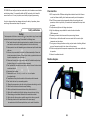
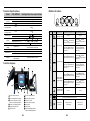
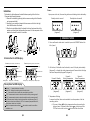
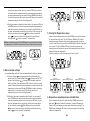
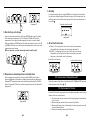
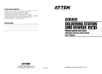
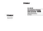
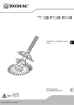
ETC-RW900D
SOLDERING STATION
SMD REWOEK 2 in 1
THERMO-CONTROL ANTI-STATIC
Intelligent lead-free rework station
User's Manual
CBN 019006
ETC-RW900D is an intelligent lead-free rework station, which combines rework station
and soldering station. It is especially suitable for R&D, production, lab of scientific
research and so on. It is easy to operate, user-friendly and greatly space-saving.
In order to keep machine from damage and insure the safety of operation, please
read through the manual and keep it for required.
Safety and Caution:
Caution
The temperature of the hot-air nozzle is 400 so it may lead to injury, fire and other
accident because of improper usage. Please abide the following terms:
1. Don't make the rework station be against people or animals. And never use it
as a hair drier and touch the heating element or blow the skin directly.
2. Never operate it near the flammable gas or substance and put it beside them
after use.
3. After use, the power should be off and it will be automatically off when the
hot air temperature is lowered, (There is fuse inside, so great attention must
be paid to superheat in case of accident.)
4. Please care for using hot-air gun, never make it fall or shake heavily and put
the heavy things on it or press the buttons improperly.
5. Don't operate with wet hands or wet wire in order not to result in short circuit
or electronic shock.
6. Keep away from children.
7. Please use the nozzle offered by manufacture and don't replace
the original nozzle.
8. Temperature will vary from the models of the nozzles, which is normal.
9. Don't touch the iron tip or surrounding metals.
10. Change the components or tip after cutting off power and waiting to cool it.
11. Don't use this device do other work except soldering.
12. Don't rap the handle to remove the doss of tip, which is bad for it.
13. Don't pull the cable but hold tightly the plug when you take out of plug.
14. Please keep good ventilation because there is smoke when solder.
15. Don't play with other people or would be easy to hurt others or yourself.
16. Please pay attention to the specifications of the power supply,
for manufacture offer different specifications, so be careful of selection.
2
Characteristics:
1. MCU computer offers PID advanced algorithms industrial control with thermocontrol and thermo-stability, which makes more exactly control temperature.
2. Dual LCD screen respectively and separately display the working state and
parameter, which is very directly. So customer can understand the output state
at a glance.
3. Temperature rapidly rises with large output power.
4. High flow diaphragm pump suitable for varies of nozzles to desolder
SMD components.
5. Dormancy, automatic shut down and other power-saving features.
6. Shortcut keys on the handle make it more convenient for the user to adjust
temperature and air volume.
7. Three groups of storage functions can bring very fast mode of switching different
groups of temperature and hot-air volume to the customers.
8. All units are equipped with temperature compensation, which ensure stable state
of operation.
9. Indicator for malfunction alert.
Machine diagram:
3
Button instructions:
Technical Specifications:
ETC-RW900D
About 900W (max)
Hot Air Rework Station
Soldering Station
Intelligent lead-free rework station
Heating:800W(max), pump (diaphragm):40W Soldering Station:50W
100-500
200-480
Convertible
Static
±2
Temperature
controlling accuracy
Static
±10
Calibration range
Celsius
Fahrenheit
Setting storage
(3 groups)
Range of air volume
Dormancy and
standby
Cold Air
Malfunction alert
Shutdown
Position Knob/Button
First function
Second function (short press < 5s) Second function (long press > 5s)
Work and shutdown
of the rework station
1 200 , 40; 2 300 , 60; 3 400 , 80
1 200
2 300 ; 3 400
020 100 level
Stopping heating, air-blowing delay and then be in the
condition of dormancy and standby.
Air-blowing made by the machine and stopping heating.
Displaying H-E
Displaying S-E
Rework Station (in the factory)
Soldering Station (in the factory)
Rework Station
Rework Station
Rework Station
Heating elements
Sensor
Shutdown in the
normal condition
Cold air delay shutdown, power off
Function diagram:
Group
Press with
knob and then
select hot-air quick key 1 to set.
Press with
knob and
deposit the setting of hot-air
quick knob 1
Press with
knob and then
select soldering station quick
key 1 to set.
Press with
knob and
deposit the setting of iron
quick knob 1
Press with
knob and then
select hot-air quick key 2 to set.
Press with
knob and
deposit the setting of hot-air
quick knob 2
Press with
knob and then
select soldering station quick
key 2 to set.
Press with
knob and
deposit the setting of iron
quick knob 2
Press with
knob and then
select hot-air quick key 3 to set.
Press with
knob and
deposit the setting of hot-air
quick knob 3
Press with
knob and then
select soldering station quick
key 2 to set.
Press with
knob and
deposit the setting of iron
quick knob 2
Value decreasing
Set temperature
and confirmation
varies of settings
12
12
4
Hot-air handle bracket
Rework station handle
Output of hot-air
Function button groups
Iron holder
Iron handle
A screen to display working
station of soldering stations
Hot-air station
handle knob
Work and shutdown
of soldering station
Rework station nozzle
Hot-air handle button group
B screen to display working
station of soldering stations
Output of soldering station
Sponge for clean iron
power switch
Group
Value increasing
Front Panel Buttons
Model
Total power
Range for temperature
controlling
Temperature unit
Temperature
controlling stability
Group
Group
To increase the Set value of hot-air station
To decrease the Set value of hot-air station
Adjustment of
air volume
Blowing cold air of
rework station
5
Awake hot air of
rework station
Installation:
Power:
The brackets for the handles must be installed when operating for the first time.
Please see the following illustration:
1. Please fix the bracket by tightening the four screws according to the illustration
and your personal habit.
2. According to your selection, dismantle the two screws on the left or the right,
which fix the bracket of the handle.
3. Place the two installation hole of the bracket to the two fixed screw holes of the
machine, and then tighten the dismantled two screws. Put the components of the
handle on the bracket to check if it is suitable.
Upon power on the unit, the reworking station and soldering station be standby.
Standby state of screen A
Standby state of screen B
(diagram 1)
(diagram 2)
. REWORK STATION
1. Power on: Rework station start to work after press the "POWER" knob at the
left of panel.
Introduction for LCD display:
A screen (rework station, same as below)
Display of status
Working mode
B screen (soldering station, same as below)
Display of status
Setting value and display
of real temperature
Setting value and display
of temperature
Temperature unit
Temperature unit
Power direction
Power direction
Setting temp. Air flow display
2. At that time, if the handle is on the bracket, screen " A" display state standby
(diagram 3), or display the setting temperature and 3 seconds later it display
the actual temperature (diagram 4, diagram 5).
Screen A: Standby
Screen A:
Setting Temperature
Screen A:
Actual Temperature
Memory temp. 1 Memory temp. 2 Memory temp. 3
Description for LCD display
Display "- - -" means the device is standby
Screen "A" displays the working state of rework station.
"P_ _" eans rework station is under the normal setting condition.
" P 0 1 " means rework station is under the condition set by memory group 1.
" P 0 2 " means rework station is under the condition set by memory group 2.
" P 0 3"means rework station is under the condition set by memory group 3.
Both screen A and screen B display " OFF" in the memory temperature area 2,
which means the device, is standby.
When the temperature area shines
the station is under the condition
available to set.
7
(diagram 3)
(diagram 4)
(diagram 5)
3. Temperature Settings
In normal condition, there are two methods to set temperature of hot-air
reworking station.
A. If screen A shines
setting temperature through operating the
button of panel. If screen A doesn't shine
you must press the
"SET"button to switch to shine
of screen A then the station
8
Under the setting condition. Then you can press "SET" button to set hot
-air rework station' s temperature and the main temperature area shines
the setting temperature, you can press UP knob or DOWN knob to adjust
the setting temperature. 4s-no-press or press SET knob, you can keep the
temperature and quit out this setting. (Diagram 6).
A. Setting temperature via handle of rework station. You can press UP knob
or DOWN knob directly to adjust temperature and the main temperature
area indicators setting temperature. 4s-no-press or press SET knob, you
can keep the temperature and quit out this setting, at that time, you can
adjust hot-air volume by pressing " " Whether screen A or screen B
shine
as you set, the device is under the setting condition and
shining area for
switch to screen "A " automatically.
Notice: continually pressing UP or DOWN knob in long time will quickly adjust
the temperature, at that time, the screen don't shine. (Same as below description)
(diagram 7)
5. Storing the Temperature values
Under normal working condition, hold down POWER knob at the left of panel,
at the same time long press (>5s) the UP knob or DOWN or SET to adjust
temperature and air volume to the required values separately in term 1 or
term 2 or term 3. But when you hold down POWER knob at the left of panel and
short press (<5s) UP or DOWN or SET knob to use the storage setting
temperature and air volume into current work temperature and air volume
(diagram8, diagram9, diagram10).
(Notice: up, down, set refer to storage term 1, term 2, term 3)
(diagram 6)
4.Hot-air volume settings
In normal working condition, there are two methods to set hot-air volume:
A. If screen A shines
setting temperature through operating the
button of panel. If screen A doesn't shine
you must press the "SET"
button to switch to shine
of screen A then the station under the
setting condition. Then you can press "SET" button to set hot-air rework
station' s temperature and the main temperature area shines the setting
temperature, you can press UP knob or DOWN knob to adjust the setting
temperature. 4s-no-press or press SET knob, you can keep the
temperature and quit out this setting (diagram 7).
B. Setting hot-air volume via handle of rework station. You can press UP
knob or DOWN knob to adjust hot-air volume and the main temperature
area indicators setting volume. 4s-no-press or press SET knob, you can
keep the volume and quit out this setting, at that time, you can adjust
hot-air volume by pressing " " When the screen A or screen B shine
as you set, the device is under the setting condition and shining
area for
switch to screen"A" automatically.
9
Screen A:
Working state of shortcut 1
Screen A:
Working state of shortcut 2
(diagram 8)
(diagram 9)
Screen A:
Working state of shortcut 3
(diagram 10)
6.Temperature comp temperature and calibration
Under normal working condition, hold down both POWER knob at left of
panel and " " knob on the handle to calibrate. Screen A will display the
character CAL, and temperature value can be calibrated by pressing UP or
DOWN knobs. Pressing the SET knob to confirm storage and quit from this
calibration (diagram 11).
10
10. Error/Fault indication
(diagram 11)
7. Dormancy
Under normal working condition, when the user put the handle on the bracket,
then the equipment will be automatically switch to the dormancy condition and
the heater also stops heating. This happens in the case when the temperature is
higher than 100 , during the hot-air station dormancy period the screen A
display character SLP (diagram 3)
Screen A: Standby
1. When "H-E" is displayed on the screen A, there is no hot air in the nozzle
(diagram13), which indicates that the heating element fails.
2. When "S-E" is displayed on the screen A, there is a fault in sensor
(diagram14), which signifies that there is something wrong with the
sensor or the related circuit of the sensor.
Screen A: no hot-air fault
Screen A: sensor fault
(diagram 13)
(diagram 14)
II. SOLDERING STATION
1.Power on
(diagram 3)
8.Conversation between cold-air and hot-air
Screen B which displays actual temperature in 3s displays setting temperature
after pressing POWER knob at the right of panel (diagram15, diagram16).
In normal condition, continually press " "knob twice and then make the
hot-air be in the state of cold-air blow (diagram12). Under the cold-air
condition, press " " knob once, recover the hot-air working condition.
(diagram 12)
Screen B:
Temperature Settings
Screen B: heating
(diagram 15)
(diagram 16)
9.Standby
Under normal working condition, the device keep the current temperature and
air volume and cut down heating to the rework station after pressing POWER
knob at the left of panel (diagram 1A), below 100 , the device is standby
(diagram1). If power is off, the soldering station is off, whole device will be off
after the temperature below 100 .
Standby state of screen A
(diagram 1A)
(diagram 1)
11
2.Temperature setting
In normal working condition, if screen B shines
or you at first continually
press SET knob twice to switch to shine
, then press the UP or DOWN knob
to adjust temperature. Screen B shines"SET" and the main temperature area
shines the setting temperature of soldering station. Stopping pressing knob or
pressing SET knob confirm and keep settings and quit from this operation
(diagram17).
12
5.Standby
(diagram 17)
In normal working condition, press POWER key at the right of panel to make
the device be standby (diagram 2). Make the power off, at the same time, the
soldering station is off and the whole station will off when the temperature is
low to 100 .
Standby state of screen B
3.Shortcut keys set storage
Under normal working condition, hold down POWER knob at the left of panel,
at the same time long press (>5s) the UP knob or DOWN or SET to adjust
temperature to the required values separately in term1 or term2 or term3.
When you hold down POWER knob at the left of panel and short press (<5s) UP
or DOWN or SET knob to use the storage setting temperature into current work
temperature and air volume.
(Notice: up, down, set refer to storage term1, term2, term3)
4.Temperature comp temperature and calibration
Under normal working condition, hold down both POWER knob at right of
panel and " " knob on the handle to calibrate soldering station temperature
(diagram18). Temperature value can be calibrated by pressing UP or DOWN
knobs. Pressing the SET knob to confirm storage and quit from this calibration
(diagram 11).
(diagram 18)
13
(diagram 2)
6.Error/Fault indication
A. When "H-E" is displayed on the screen A, there is no temperature
(diagram19),which indicates that the heating element fails.
B. When "S-E" is displayed on the screen A, there is a fault in sensor
(diagram20), which signifies that there is something wrong with
the sensor or the related circuit of the sensor.
Screen B: fault of heating
screen B: fault of sensor
(diagram 19)
(diagram 20)
III. Conversion of temperature unit
Under the power off condition, hold down the UP, DOWN and SET knob and
then put power on to switch / .
IV. Replacement of heater
Please follow the following steps for the successful replacement of the heating
element of hot-air rework station:
A. Cut down power, please refer to the following diagram to replace heater
after it is cool.
B. Based on diagram, loosen the three screws of the handle.
C. Dismantle the upper cover of the handle, pull out the ground wire on the
duct and take out the fan.
D. Take out the heating element from PCB board.
14
E. Insert new heating element in PCB board, pay attention to install properly.
F. Install it as the contrary method of remove.
Top shell
PCB
Quartz tube
Hot air tube
List of accessories:
ETC-RW900D
1 unit
Power cord
1 strip
Nozzle
1 set
Bracket
1 set
handle
1 pc
iron holder
1 set
User manual
1 copy
Lower shell
WARNING: This tool be placed on its stand when not in use
heating element
Please follow the following steps for the successful replacement of heating
element of soldering station:
A. Cut down power; replace the heating element after it is cool.
B. As following diagram, unscrew the nut , take out the stainless steel
cap
and iron tip , then unscrew the fixed holder , desoldering the
heating element .
C. Replace the good condition heating element and install it as the contrary
method of remove.
15
The instructions for heat guns and hand-held paint strippers shall
include the substance of following:
A fire may result if the appliance is not used with care, therefore
be careful when using the appliance in places where there are
combustible materials:
Do not apply to the same place for a long time;
Do not use in presence of an explosive atmosphere;
Be aware that heat may be conducted to combustible materials
that are out of sight ;
Place the appliance on its stand after use and allow it to cool
down before storage;
Do not leave the appliance unattended when it is switched on;
16
17
18
Nozzles
Interchangeable soldering tips of soldering station