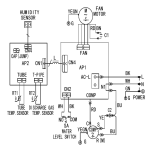
1
Document 1.09.619 EN Valid from 3.2.2015 NN UA Updated 5 May 2015 L E F F IC I E N C Y TIN RA A Types 3722 3702 3712 ER TA IR H EAT REC O V Manual AC Y G O F E XT R A+ MANUAL Models Vallox 096 MV Vallox 110 MV Vallox 145 MV MANUAL 2 MANUAL CONTENTS 1.INTRODUCTION •The main parts of the ventilation unit •System description •General safety Instructions, guarantee and liability •MyVallox Control control panel buttons •Starting up and shutting down the unit 2.DEPLOYMENT WIZARD •Basic settings (setting the language, time and date) •Expert settings (setting the password and access rights, parental controls, fan settings, profile settings) 3.USING THE UNIT •Ventilation profiles •Temperatures and Sensors •Settings (filter, display settings, time and date, week clock, switching the unit off) 4.MAINTENANCE •Filters •Heat recovery cell •Fans •Condensing water •Troubleshooting 4 10 19 38 5.TECHNICAL SPECIFICATIONS •Technical data, supply/extract air volumes, fan curves, sound values, main components, measurement points, dimensions and duct outlets •Internal electrical connection •External electrical connection •Heating/cooling radiator operation chart 6.MOUNTING •Wall mounting •Measuring tubes •Ceiling mounting •Floor mounting •Condensing water 44 56 7.CERTIFICATE OF CONFORMITY 60 8.EXPLODED VIEW AND PARTS LIST 61 9.USER LEVEL DIAGRAMS 64 NOTE: You can find your MyVallox account at www.MyVallox.com 3 © Vallox • We reserve the right to make changes without prior notice INTRODUCTION INTRODUCTION THE MAIN PARTS OF THE VENTILATION UNIT R model in the figure EXTRACT AIR FAN (BEHIND THE PROTECTIVE COVER) SUPPLY AIR FAN (BEHIND THE EXTRACT AIR DUCT) OUTDOOR AIR FILTER F7 HEAT RECOVERY CELL SUMMER / WINTER FLAP OUTDOOR AIR FILTER G4 EXTRACT AIR FILTER G4 POST-HEATING RADIATOR (BEHIND THE EXTRACT AIR DUCT) SAFETY SWITCH CONTROL PANEL CARBON DIOXIDE SENSOR HUMIDITY SENSOR INTERNAL HUMIDITY SENSOR 4 INTRODUCTION INTRODUCTION SYSTEM DESCRIPTION Internet Additional switch WLAN Router Sensors WLAN/LAN 5 Modbus © Vallox • We reserve the right to make changes without prior notice INTRODUCTION INTRODUCTION DIFFERENCES BETWEEN THE UNITS • • • • • • • Power Size Vallox 096 MV does not have an additional heater. Vallox 110 MV and Vallox 145 MV have an additional heater. Weight In the model Vallox 096 MV, there is a sealing tape at the bottom of the heat recovery cell. In other models, there is a separate sealing bar under the heat recovery cell. Standard delivery options vary from country to country. The available options vary from country to country. Mounting options: • • Models Vallox 096 MV and Vallox 110 MV can be mounted either on the wall, or on the ceiling by using a mounting plate (optional). These models cannot be mounted on the floor. Model Vallox 145 MV can be mounted either on the wall, or on the floor by using a floor rack (optional). This model cannot be mounted on the ceiling. GENERAL SAFETY INSTRUCTIONS For safe and proper handling, it is necessary to know the basic safety regulations and the intended usage of the ventilation system. Read this manual before operating the ventilation unit. Keep this manual for later use. In case of loss, you can download the manual from our website. This user manual contains all important hints for operating the system safely. This user manual must be observed by all persons who operate and maintain the ventilation system. Furthermore, observe all local accident prevention regulations. INTENDED USE All Vallox ventilation units are designed to take care of appropriate and continuous ventilation, in such a way that people and structures will remain healthy. GUARANTEE AND LIABILITY Demands on guarantee and liability are excluded if they are caused by the following reasons: • Unintended use of the ventilation system and the control unit • Improper mounting, initial operation and operation • Operating the ventilation system with a defective safety system • Ignoring hints for transportation, mounting, operation and maintenance • Unauthorized structural alteration and changes of the programming • Disasters due to extraneous elements and force majeure 6 IMPORTANT If necessary, you can find more information at www.vallox.com INTRODUCTION INTRODUCTION INSTALLATION Installation and setup should only be carried out by qualified experts. Electrical installations and connections must only be carried out by electricians, and according to the local regulations. CONTROL PANEL BUTTONS BUTTON DESCRIPTION Change profile button. This button allows you to change the ventilation profile of the device. Profile Information button. This button allows you to view the currently active profile information. Temperature button. Pressing this button displays information on temperatures and sensors. Settings button. Press this button to open the settings. Back button. Pressing this button takes you backwards in the menu. Left arrow button. Pressing this button takes you to the left in the menu. Right arrow button. Pressing this button takes you to the right in the menu. OK button. Press this button to accept the selected option. Select button. Press this button to select an option from the list. Edit button. Press this button to edit settings. Plus button. Press this button to: •Increase the value of the setting. •Move to the next menu item. •Move from a one-day view to a week view in the temperature, humidity and carbon dioxide graphs. Minus button. Press this button to: •Reduce the value of the setting. •Return to the previous menu item. •Move from a week view to a one-day view in the temperature, humidity and carbon dioxide graphs. NOTE The MyVallox Control control panel contains the buttons described in the following table. You can press the graphical user interface buttons by using the ring shaped physical buttons below the control panel screen. The system does not have a touch screen. Up arrow button. Pressing this button takes you upwards in the menu. Down arrow button. Pressing this button takes you downwards in the menu. Statistics button. This button opens the temperature, humidity and carbon dioxide graphs (1 day / week). These icons indicate the settings hierarchy level. This icon indicates that the feature is disabled at your user level. The parental controls lock code is 1001. 7 © Vallox • We reserve the right to make changes without prior notice INTRODUCTION INTRODUCTION INTRODUCTION Ventilation has to be constant for the indoor air to stay healthy for the dwellers and the structures of the dwelling. Even for longer holidays, it is not advisable to stop the ventilation, because the indoor air will become stuffy and, during the heating season, the indoor air humidity may condense in the ventilation ductwork and structures, causing moisture damage. You can control and automate the Vallox ventilation unit operation in the following ways: • • • • By using a control panel installed in the building Through the My Vallox Home local network connection and the Web interface Through the My Vallox Cloud cloud service and the Web interface Through a remote monitoring service or building automation by using voltage signals or Modbus messages The required ventilation may also be adjusted automatically with the optional carbon dioxide and humidity sensors. In this case, ventilation remains optimal even if the dwelling is unoccupied. By using the week clock, you can create just the right ventilation for your individual lifestyle. WARNING The unit is not intended for use by children (under 8 years) or by persons with reduced sensory, physical, or mental capabilities, or lack of knowledge and experience, that limit the safe operation of the unit. These people can use the product under the supervision of a person responsible for their safety, or as directed. TIP The MyVallox Control control panel automatically switches to sleep mode when the pre-set sleep time has elapsed. If you want to wake up the MyVallox Control control panel, press any button on the control panel. 8 INTRODUCTION INTRODUCTION The ventilation specialist has made the ventilation system basic settings, based on the ventilation plan. The basic settings are: • • • • • • User interface language. Time and date. System administrator password. The installer has given you the system administrator password. Possible parental controls. Fan settings. User profile settings, such as the temperature. If you are satisfied with the basic settings made by the installer, do not make changes to them. STARTING THE UNIT If you are starting the ventilation unit for the first time, or after any maintenance procedure, connect the plug to the outlet, starting the unit. When the unit starts up, the diagnostic display will appear for a few seconds, until the At home profile main screen is opened. If the unit is switched off from the control panel, you can start the ventilation unit by pressing any button on the control panel. NOTE The first launch of the unit may take a while, as the control panel will format its software and verify that it has the latest software version. SWITCHING THE UNIT OFF If you want to switch off the ventilation unit, proceed as follows: 1. Select Settings > Turn unit OFF. 2. Press the OK button. 3. The system asks for confirmation. 4. Press the OK button. 5. The ventilation unit is now switched off. 9 © Vallox • We reserve the right to make changes without prior notice DEPLOYMENT WIZARD BASIC SETTINGS DEPLOYMENT WIZARD 1. Start the Vallox ventilation device by plugging in the power cord to the power outlet. 2. When you start the Vallox ventilation device for the first time, the Vallox logo is shown on the MyVallox Control control panel. 3. Press the OK button. 4. The deployment wizard is launched. SELECTING THE LANGUAGE Select the user interface language as follows: 1. Use the arrow buttons to select the language you want, for example, English: 2. Press the OK button. 3. The selected language is now English. SET THE TIME When the deployment wizard prompts you to set the date and time, the Time and date screen is opened first: 1. Use the Plus and Minus buttons to set the hours. 2. Press the Right arrow button. 3. Use the Plus and Minus buttons to set the minutes. 4. The time is now set. 5. Proceed to the next phase by pressing the Right arrow button. SET THE 24 OR 12 HOUR CLOCK By default, the system uses a 24 hour clock. If you want to use the 24 hour clock, proceed to the next step by pressing the Arrow right button. If you want to use the 12 hour clock, proceed as follows: 1. Press the Minus button. The 24-Hour Time setting value is changed to Off. 2. Proceed to the next phase by pressing the Right arrow button. 10 DEPLOYMENT WIZARD BASIC SETTINGS SET THE AUTOMATIC DAYLIGHT SAVING TIME By default, the system automatically switches to the summer time. If you want to use the automatic daylight saving time, proceed to the next step by pressing the Arrow right button. If you want to use the manual daylight saving time, proceed as follows: 1. Press the Minus button. The Dayl.Saving Time setting value is changed to Off. 2. Manual daylight saving time is now set. 3. Proceed to the next phase by pressing the Right arrow button. SET THE DATE 1. 2. 3. 4. 5. 6. 7. Use the Plus and Minus buttons to set the date. Press the Right arrow button. Use the Plus and Minus buttons to set the month. Press the Right arrow button. Use the Plus and Minus buttons to set the year. Press the OK button: The date is now set. FINISHING UP THE DEPLOYMENT When you have made the basic settings for the deployment, the acknowledgement screen is opened. If you want to continue and make the advanced settings for the ventilation device, press the OK button. If you want to intermit the deployment and use the ventilation device on factory settings, press the Back button: You can make the expert settings for the ventilation device later. EXPERT SETTINGS The following chapters describe the Vallox ventilation device deployment wizard phase, where you make the expert settings. IMPORTANT Some deployment phases require special equipment, such as an air flow meter. 11 © Vallox • We reserve the right to make changes without prior notice DEPLOYMENT WIZARD EXPERT SETTINGS PASSWORD AND ACCESS LEVEL Once you have finished up making the basic settings, the deployment wizard moves on to setting the system password. NOTE If you set the password as 0000, the password inquiry is not used. 1. The deployment wizard Password and access level screen is opened. 2. Set the first digit of the password by using the Up arrow and Down arrow buttons. Proceed to the next digit by pressing the Right arrow button. 3. Set the second, third and fourth digit in the same manner as the first digit. 4. Press the OK button. 5. The password is now set. WRITE DOWN THE PASSWORD YOU SET: USER LEVEL There are three user levels: • • • Extensive — On the extensive user level, the user can access every menu on the control panel.. Normal — On the normal user level, the user's access to some menus is restricted. Limited — The users on the limited user level can only carry out the basic tasks required to operate the ventilation device. For more information on user levels, see chapter 9, User level diagrams. When you want to set the system user level, proceed as follows: 1. The deployment wizard User level screen is opened. 2. Use the Plus and Minus buttons to set the user level. 3. Press the Right arrow button. 4. The user level is now set. PARENTAL CONTROLS Parental controls lock the control panel screen in a way that no one can damage the ventilation unit by pressing the control panel buttons randomly. When you want to set the system child lock, proceed as follows: 1. The deployment wizard Password and access level screen is opened. 2. Set the parental controls on or off by using the Plus and Minus buttons. 3. Press the OK button. 4. The parental controls are now set. 12 PARENTAL CONTROLS ACCESS CODE: 1 0 0 1 DEPLOYMENT WIZARD EXPERT SETTINGS FAN SETTINGS In the following chapters, you will set the output ratio between the supply and extract air fans. IMPORTANT Adjust the air flows, according to the values in the ventilation plan. Try to adjust the air flows in a way that you do not have to choke the air flows at the valves. This is the most energy efficient set up. WARNING The ventilation specialist has made the supply and exhaust air settings when deploying the Vallox ventilation unit. If you make changes to the settings, ensure that they conform with the ventilation plan. First, set both values as close to the ideal value as possible. The ideal values are presented in the supply and extract air volume graphs. If, at the beginning, the air flows differ greatly from each other, the ventilation unit may have to carry out extra defrosting cycles on sub-zero temperatures, thus complicating the adjustment of the air flows. Check the air flows by measuring them at the valves, and fine tune the percentage values, if necessary. NOTE If the outside air is extremely cold (below -10°C on an aluminium cell or below -3°C on a plastic cell), the ventilation device may have to defrost the heat exchanger cell. If this occurs, you cannot adjust the air flows and the Defrosting figure is shown on the control panel. SUPPLY AIR When you want to make the system supply air settings, proceed as follows: 1. The deployment wizard Fan settings screen is opened. 2. Set the supply air quantity as a percentage of the maximum by using the Plus and Minus buttons. The fan speed (1/min) will change, according to the percentage value. 3. Once you have set the supply air fan settings, press the Right arrow button. EXTRACT AIR When you want to make the system extract air settings, proceed as follows: 1. The deployment wizard Fan settings screen is opened. 2. Set the extract air quantity as a percentage of the maximum by using the Plus and Minus buttons. The fan speed (1/min) will change, according to the percentage value. 3. Press the OK button. 4. The extract air fan ratio is now set. 13 © Vallox • We reserve the right to make changes without prior notice DEPLOYMENT WIZARD EXPERT SETTINGS PROFILE SETTINGS In the following chapters, you can make ventilation settings for the system profiles. HOME PROFILE When you want to make the At home profile settings, proceed as follows: 1. The deployment wizard Home screen will open. NOTE Once you have set the basic ventilation air flow rates, the higher percentage value will default to the At home profile fan speed value. We recommend this basic amount of ventilation for the At home profile setting. If necessary, you can change it. 2. Set the At home profile fan speed as a percentage of the maximum by using the Plus and Minus buttons. 3. The At home profile fan speed value is now set. 4. Press the Right arrow button. 5. The temperature setup screen is opened. 6. Set the desired supply air temperature for the At home profile by using the Plus and Minus buttons. You can adjust the temperature in the range of +10°C – +25°C. 7. The At home profile supply air temperature is now set. 8. Press the Right arrow button. 9. The setup screen for the automatic fan speed control, based on the relative humidity, appears. 10. Use the Plus and Minus buttons to select whether the automatic fan speed control, based on the relative humidity, is used or not. 11. The automatic fan speed control, based on the relative humidity, is now set. 12. Press the Right arrow button. 13. The setup screen for the automatic fan speed control, based on the carbon dioxide content, appears. 14. Use the Plus and Minus buttons to select whether the automatic fan speed control, based on the carbon dioxide content, is used or not. 15. The automatic fan speed control, based on the carbon dioxide content, is now set. 16. Press the OK button. 14 DEPLOYMENT WIZARD EXPERT SETTINGS AWAY PROFILE When you want to make the Away profile settings, proceed as follows: 1. The deployment wizard Away profile screen is opened. NOTE Once you have set the fan speed for the At home profile, the fan speed for the Away profile will default to -30% of the At home profile fan speed. We recommend this basic amount of ventilation for the Away profile setting. If necessary, you can change it. Set the Away profile fan speed as a percentage of the maximum by using the Plus and Minus buttons. 3. The Away profile fan speed value is now set. 4. Press the Right arrow button. 5. The temperature setup screen is opened. 6. Set the desired supply air temperature for the Away profile by using the Plus and Minus buttons. You can adjust the temperature in the range of +10°C – +25°C. 7. The Away profile supply air temperature is now set. 8. Press the Right arrow button. 9. The setup screen for automatic fan speed control, based on the relative humidity, appears. 10. Use the Plus and Minus buttons to select whether the automatic fan speed control, based on the relative humidity, is used or not. 11. The automatic fan speed control, based on the relative humidity, is now set. 12. Press the Right arrow button. 13. The setup screen for the automatic fan speed control, based on the carbon dioxide content, appears. 14. Use the Plus and Minus buttons to select whether the automatic fan speed control, based on the carbon dioxide content, is used or not. 15. The automatic fan speed control, based on the carbon dioxide content, is now set. 16. Press the OK button. 2. 15 © Vallox • We reserve the right to make changes without prior notice DEPLOYMENT WIZARD EXPERT SETTINGS BOOST PROFILE When you want to make the Boost profile settings, proceed as follows: 1. The deployment wizard Boost profile screen is opened. NOTE Once you have set the fan speed for the At home profile, the fan speed for the Boost profile will default to +30% of the At home profile fan speed. We recommend this basic amount of ventilation for the Boost profile setting. If necessary, you can change it. 2. Set the Boost profile fan speed as a percentage of the maximum by using the Plus and Minus buttons. 3. Press the Right arrow button. 4. The temperature setup screen is opened. 5. Set the desired supply air temperature for the Boost profile by using the Plus and Minus buttons. You can adjust the temperature in the range of +10°C – +25°C. 6. Press the Right arrow button. 7. The setup screen for the automatic fan speed control, based on the relative humidity, appears. 8. Use the Plus and Minus buttons to select whether the automatic fan speed control, based on the relative humidity, is used or not. 9. Press the Right arrow button. 10. The setup screen for the automatic fan speed control, based on the carbon dioxide content, appears. 11. Use the Plus and Minus buttons to select whether the automatic fan speed control, based on the carbon dioxide content, is used or not. 12. Press the Right arrow button. 13. The profile timer setting screen is displayed. 14. Use the Plus and Minus buttons to select whether the profile timer function is enabled or not. The options are: •On - When the timer is enabled, the Boost profile is only on for the period defined in the timer. •Off — When the timer is disabled, the Boost profile is used until you (or the week clock) change the profile. 15. Press the Right arrow button. 16. The timer duration setting screen appears. 17. Set the profile timer duration in minutes by using the Plus and Minus buttons. 18. Press the OK button. 16 DEPLOYMENT WIZARD EXPERT SETTINGS FIREPLACE PROFILE When you want to make the Fireplace function settings, proceed as follows: 1. The deployment wizard Fireplace function profile screen is opened. 2. Set the profile timer duration in minutes by using the Plus and Minus buttons. 3. The profile duration is now set. 4. Press the Right arrow button. 5. The screen for setting the profile supply air fan speed appears. 6. Set the Fireplace function supply air fan speed as a percentage of the maximum by using the Plus and Minus buttons. TIP In the fireplace mode, we recommend that you increase the supply air fan speed, in order to obtain a positive pressure at the ventilation zone. We do not recommend reducing the extract air fan speed. 7. The Fireplace function supply air fan speed is now set. 8. Press the Right arrow button. 9. The screen for setting the profile extract air fan speed appears. 10. Set the Fireplace function extract air fan speed as a percentage of the maximum by using the Plus and Minus buttons. 11. The Fireplace function extract air fan speed is now set. 12. Press the Right arrow button. 13. The profile timer setting screen is displayed. 14. Use the Plus and Minus buttons to select whether the profile timer function is enabled or not. The options are: •On — When the timer is enabled, the Fireplace function is only on for the period defined in the timer. •Off — When the timer is disabled, the Fireplace function is used until you (or the week clock) change the profile. 15. The profile timer function is now set. 16. Press the OK button. 17. The Fireplace function settings are now complete. 17 © Vallox • We reserve the right to make changes without prior notice DEPLOYMENT WIZARD EXPERT SETTINGS FINISHING UP When you have completed the wizard, the Setup done! screen will open. Finish up the deployment, as follows: 1. If you want to go back to repair or change a value, use the arrow buttons to select the desired line and press the OK button. 2. Repeat the selected deployment phase or phases, until you are satisfied with the settings. 3. When you are satisfied with the settings, use the arrow buttons to select Start and press the OK button. 18 USING THE UNIT VENTILATION PROFILES THE VALLOX VENTILATION UNIT HAS FOUR VENTILATION PROFILES: AT HOME AWAY BOOST Use this ventilation profile when the apartment or the premises are occupied Use this ventilation profile when the dwelling or premises are not occupied, for example, during a trip or other long absence. Use this profile when there are a lot of people in the apartment or on the premises, or when you want to enhance the ventilation for other reasons. FIREPLACE FUNCTION Use this ventilation profile when, for example, you are making a fire in the fireplace. This profile is, primarily, used to create a momentary overpressure in the housing. VENTILATION PROFILE USER INTERFACE SYMBOLS The profile main screens use the following symbols: Table 2. Profile symbols SYMBOL Example of a profile main screen DESCRIPTION When this symbol appears on the screen, either the Home, Away or Boost profile is in use. The week clock is not used. When this symbol appears on the screen, either the Home, Away or Boost profile is in use. The week clock is used. When this symbol appears on the screen, the Fireplace profile is in use. The week clock is possibly used. These symbols indicate the fan speed of the currently active profile. The smallest fan icon indicates that the Away profile is in use, and largest fan icon, in turn, indicates that the Boost profile is used. Drop symbols indicate the relative amount of moisture in the air. The symbols are: • One drop — A humidity sensor is installed and the humidity level is normal. • Two drops — The humidity level is slightly elevated. The fan speed is increased, if automatic adjustment is allowed. • Three drops — The humidity level is remarkably elevated. The fan speed is increased, if automatic adjustment is allowed. These symbols indicate the carbon dioxide concentration in the air. The colour codes are: • Green — A carbon dioxide sensor is installed and the carbon dioxide level is normal. • Orange — The carbon dioxide level is slightly elevated. The fan speed is increased, if automatic adjustment is allowed. • Red — The carbon dioxide level is remarkably elevated. The fan speed is increased, if automatic adjustment is allowed. 19 © Vallox • We reserve the right to make changes without prior notice USING THE UNIT VENTILATION PROFILES CHANGING THE PROFILE If you want to change the ventilation profile, proceed as follows: 1. P ress the Change profile button until the desired ventilation profile icon is displayed in the screen. 2. Wait until the ventilation profile main screen is displayed. 3. The ventilation profile has been changed. VIEWING VENTILATION PROFILE INFORMATION VIEWING THE AT HOME PROFILE INFORMATION If you want to view the At home profile settings, proceed as follows: 1. Open the At home profile main view. 2. Press the Profile information button. 3. The first information screen for the profile appears. This screen contains the following information: • Supply air — This value indicates the temperature of the air blown indoors and its set value (in parentheses), if the supply air is warmer than the set value. • Outside air — This value indicates the outside air temperature. • Fan speed — This value indicates the fan speed. If the ventilation unit has an automatic fan speed boost on, the set value is shown in parentheses, and then the actual fan speed. • Cell status — Cell status indicates the status of the ventilation device heat exchanger cell. Possible statuses are: •Heat recovery — The heat recovery cell heats the air streaming in from outdoors. •Cooling — The heat recovery cell cools the air streaming in from outdoors. •Cell bypass — The inflowing air by-passes the heat recovery cell. •Defrosting — The heat recovery cell is being defrosted. 4. Press the Right arrow button. 5. The second information screen for the profile appears. This screen contains the following information: • Humidity — This value indicates the maximum measured humidity value that the system has read from the sensors. • Carbon dioxide — This value indicates the maximum measured carbon dioxide value that the system has read from the sensors. • Change filters — This value indicates the next recommended filter change date. • Used days — This value indicates how long the device has been running. 20 USING THE UNIT VENTILATION PROFILES VIEWING THE AWAY PROFILE INFORMATION If you want to view the Away profile settings, proceed as follows: 1. Open the Away profile main view. 2. Press the Profile information button. 3. The first information screen for the profile appears. This screen contains the following information: • Supply air — This value indicates the temperature of the air blown indoors and its set value (in parentheses), if the supply air is warmer than the set value. • Outside air — This value indicates the outside air temperature. • Fan speed — This value indicates the fan speed. If the ventilation unit has an automatic fan speed boost on, the set value is shown in parentheses, and then the actual fan speed. • Cell status — Cell status indicates the status of the ventilation device heat exchanger cell. Possible statuses are: •Heat recovery — The heat recovery cell heats the air streaming in from outdoors. •Cooling — The heat recovery cell cools the air streaming in from outdoors. •Cell bypass — The inflowing air by-passes the heat recovery cell. •Defrosting — The heat recovery cell is being defrosted. 4. P ress the Right arrow button. 5. T he second information screen for the profile appears. This screen contains the following information: • Humidity — This value indicates the maximum measured humidity value that the system has read from the sensors. • Carbon dioxide — This value indicates the maximum measured carbon dioxide value that the system has read from the sensors. • Change filters — This value indicates the next recommended filter change date. • Used days — This value indicates how long the device has been running. 21 © Vallox • We reserve the right to make changes without prior notice USING THE UNIT VENTILATION PROFILES VIEWING THE BOOST PROFILE INFORMATION If you want to view the Boost profile settings, proceed as follows: 1. Open the Boost profile main view. 2. Press the Profile information button. 3. The first information screen for the profile is opened. This screen contains the following information: • Supply air — This value indicates the temperature of the air blown indoors and its set value (in parentheses), if the supply air is warmer than the set value. • Outside air — This value indicates the outside air temperature. • Fan speed — This value indicates the fan speed. If the ventilation unit has an automatic fan speed boost on, the set value is shown in parentheses, and then the actual fan speed. • Cell status — Cell status indicates the status of the ventilation device heat exchanger cell. Possible statuses are: •Heat recovery — The heat recovery cell heats the air streaming in from outdoors. •Cooling — The heat recovery cell cools the air streaming in from outdoors. •Cell bypass — The inflowing air by-passes the heat recovery cell. •Defrosting — The heat recovery cell is being defrosted. 4. P ress the Right arrow button. 5. T he second information screen for the profile is opened. This screen contains the following information: • Humidity — This value indicates the maximum measured humidity value that the system has read from the sensors. • Carbon dioxide — This value indicates the maximum measured carbon dioxide value that the system has read from the sensors. • Change filters — This value indicates the next recommended filter change date. • Used days — This value indicates how long the device has been running. VIEWING THE FIREPLACE FUNCTION INFORMATION If you want to view the Fireplace function settings, proceed as follows: 1. O pen the Fireplace function main view. 2. The profile main screen contains a summary of the profile data. Also see Table 2, "Profile symbols". 3. Press the Profile information button. 22 USING THE UNIT VENTILATION PROFILES 4. T he first information screen for the profile appears. This screen contains the following information: • • • Duration — This value indicates the enhanced ventilation duration when the Fireplace function is activated. The value is expressed in hours and minutes. Supply fan speed — This value indicates the percentage of the supply air fan speed in relation to the maximum speed. Extract fan speed — This value indicates the percentage of the extract air fan speed in relation to the maximum speed. MODIFYING THE PROFILE SETTINGS IMPORTANT The system uses, but does not save the settings automatically. Your settings may be lost during, for example, a power outage. Remember to save your settings by selecting Expert settings > Save and restore settings. MODIFYING THE AT HOME PROFILE SETTINGS Open the At home profile main view. Press the Profile information button. Press the Edit button. The fan speed setup screen is opened. Set the At home profile fan speed as a percentage of the maximum by using the Plus and Minus buttons. 6. Press the Right arrow button. 7. The temperature setup screen is opened. 8. Set the desired supply air temperature for the At home profile by using the Plus and Minus buttons. You can adjust the temperature in the range of +10°C — +25°C. The recommended temperature is +15°C or 2—3°C below the room temperature. 9. Press the Right arrow button. 10. The setup screen for the automatic fan speed control, based on the relative humidity, appears. 11. Use the Plus and Minus buttons to select whether the automatic fan speed control, based on the relative humidity, is used or not. 12. Press the Right arrow button. 13. The setup screen for the automatic fan speed control, based on the carbon dioxide content, appears. 14. Use the Plus and Minus buttons to select whether the automatic fan speed control, based on the carbon dioxide content, is used or not. 15. Press the OK button. 1. 2. 3. 4. 5. 23 © Vallox • We reserve the right to make changes without prior notice USING THE UNIT VENTILATION PROFILES MODIFYING THE AWAY PROFILE SETTINGS Open the Away profile main view. Press the Profile information button. Press the Edit button. The fan speed setup screen is opened. Set the Away profile fan speed as a percentage of the maximum by using the Plus and Minus buttons. 6. Press the Right arrow button. 7. The temperature setup screen is opened. 8. Set the desired supply air temperature for the Away profile by using the Plus and Minus buttons. You can adjust the temperature in the range of +10°C — +25°C. The recommended temperature is +15°C or 2—3°C below the room temperature. 9. Press the Right arrow button. 10. The setup screen for automatic fan speed control, based on the relative humidity, appears. 11. Use the Plus and Minus buttons to select whether the automatic fan speed control, based on the relative humidity, is used or not. 12. Press the Right arrow button. 13. The setup screen for the automatic fan speed control, based on the carbon dioxide content, appears. 14. Use the Plus and Minus buttons to select whether the automatic fan speed control, based on the carbon dioxide content, is used or not. 15. Press the OK button. 1. 2. 3. 4. 5. 24 USING THE UNIT VENTILATION PROFILES MODIFYING THE BOOST PROFILE SETTINGS When you want to edit the Boost profile settings, proceed as follows: 1. Open Boost profile main view. 2. Press the Profile information button. 3. Press the Edit button. 4. The fan speed setup screen is opened. 5. Set the Boost profile fan speed as a percentage of the maximum by using the Plus and Minus buttons. 6. Press the Right arrow button. 7. The temperature setup screen is opened. 8. Set the desired supply air temperature for the Boost profile by using the Plus and Minus buttons. The recommended temperature is +15°C or 2—3°C below the room temperature. You can adjust the temperature in the range of +10°C — +25°C. 9. Press the Right arrow button. 10. The setup screen for the automatic fan speed control, based on the relative humidity, appears. 11. Use the Plus and Minus buttons to select whether the automatic fan speed control, based on the relative humidity, is used or not. 12. Press the Right arrow button. 13. The setup screen for the automatic fan speed control, based on the carbon dioxide content, appears. 14. Use the Plus and Minus buttons to select whether the automatic fan speed control, based on the carbon dioxide content, is used or not. 15. Press the Right arrow button. 16. The profile timer setting screen is opened. 17. Use the Plus and Minus buttons to select whether the profile timer function is enabled or not. The options are: •On — When the timer is enabled, the Boost profile is only on for the period defined in the timer. •Off — When the timer is disabled, the Boost profile is used until you (or the week clock) change the profile. 18. Press the Right arrow button. 19. The profile timer duration setting screen is opened. 20. Set the profile timer duration by using the Plus and Minus buttons. 21. Press the OK button. 25 © Vallox • We reserve the right to make changes without prior notice USING THE UNIT VENTILATION PROFILES MODIFYING THE FIREPLACE FUNCTION SETTINGS When you want to edit the Fireplace function settings, proceed as follows: Open the Fireplace function main view. Press the Profile information button. Press the Edit button. The fan speed setup screen is opened. Use the Plus and Minus buttons to set the Fireplace function duration in minutes. This value determines how long the profile is enabled when you switch it on. 6. Press the Right arrow button. 7. The screen for setting the profile supply air fan speed appears. 8. Set the Fireplace function supply air fan speed as a percentage of the maximum by using the Plus and Minus buttons. 1. 2. 3. 4. 5. TIP In the fireplace mode, we recommend that you increase the supply air fan speed, in order to obtain a positive pressure at the ventilation zone. We do not recommend reducing the extract air fan speed. 9. Press the Right arrow button. 10. The screen for setting the profile extract air fan speed will appear. 11. Set the Fireplace function extract air fan speed as a percentage of the maximum by using the Plus and Minus buttons. 12. Press the Right arrow button. 13. The profile timer setting screen is displayed. 14. Use the Plus and Minus buttons to select whether the profile timer function is enabled or not. The options are: •On — When the timer is enabled, the Fireplace function is only on for the period defined in the timer. •Off — When the timer is disabled, the Fireplace function is used until you (or the week clock) change the profile. 15. Press the OK button. 26 USING THE UNIT TEMPERATURES AND SENSORS VIEWING TEMPERATURE DATA When you want to view the system temperature and sensor data, proceed as follows: 1. Select Settings > Temperatures and sensors. 2. Press the OK button. 3. The temperature and sensors summary screen is opened. This screen contains the following information: • • • • Indoor — This value indicates the temperature of the air flowing into the unit, to be removed from the premises. Outdoor — This value indicates the temperature of the air flowing into the unit from outdoors. Supply — This value indicates the temperature of the air flowing into the premises. Exhaust — This value indicates the temperature of the air flowing outdoors. TIP You can open the system temperature and sensor data by pressing the temperature button on the profile screen. VIEWING TEMPERATURE STATISTICS When you want to view the system temperature statistics, proceed as follows: Select Settings > Temperatures and sensors. Press the OK button. The temperatures summary screen is opened. Press the Statistics button. A graph is opened, describing the indoor air temperature over the last 24 hours. 6. If you want to view weekly statistics, press the Plus button. 7. A graph is opened, describing the indoor air temperature over the last seven days. 8. You can return to daily statistics by pressing the Minus button. 9. You can return to the temperature type selection by pressing the Back button. 10. Press the Right arrow button. 11. A graph is opened, describing the outdoor air temperature over the last 24 hours. 12. If you want to view weekly statistics, press the Plus button. 13. A graph is opened, describing the outdoor air temperature over the last seven days. 14. You can return to daily statistics by pressing the Minus button. 15. You can return to the temperature type selection by pressing the Back button. Indoor air Outdoor air Supply air Waste air 1 day 1 week 1. 2. 3. 4. 5. 27 Indoor air temperature graph for the last 24 hours. The outside and supply air values are presented on a similar screen. You can view the graph in one day or in one week periods. © Vallox • We reserve the right to make changes without prior notice USING THE UNIT TEMPERATURES AND SENSORS 16. Press the Right arrow button. 17. A graph is opened, describing the supply air temperature over the last 24 hours. 18. If you want to view weekly statistics, press the Plus button. 19. A graph is opened, describing the supply air temperature over the last seven days. 20. You can return to daily statistics by pressing the Minus button. 21. You can return to the temperature type selection by pressing the Back button. 22. Press the Right arrow button. 23. A graph is opened, describing the waste air temperature over the last 24 hours. 24. If you want to view weekly statistics, press the Plus button. 25. A graph is opened, describing the waste air temperature over the last seven days. 26. You can return to daily statistics by pressing the Minus button. 27. You can return to the temperature type selection by pressing the Back button. 28. To exit the menu, press the Back button. VIEWING HUMIDITY AND CARBON DIOXIDE VALUES When you want to view individual humidity and carbon dioxide sensor data, proceed as follows: Select Settings > Temperatures and sensors. Press the OK button. The temperature and sensors summary screen is opened. Press the Right arrow button. A screen displaying the maximum humidity value from the air humidity sensors is opened. The value refers to the relative humidity of the air. 6. Press the Right arrow button. 7. A screen displaying the maximum humidity value from the air humidity sensors is opened, again. 8. Press the Right arrow button. 9. A screen displaying the maximum carbon dioxide value from the air carbon dioxide sensors is opened. 10. Press the Right arrow button. 11. A screen displaying the maximum carbon dioxide value from the air carbon dioxide sensors is opened, again. 12. To exit the menu, press the Back button. 1. 2. 3. 4. 5. 28 USING THE UNIT TEMPERATURES AND SENSORS VIEWING HUMIDITY AND CARBON DIOXIDE STATISTICS When you want to view statistics on the humidity and carbon dioxide values, proceed as follows: Select Settings > Temperatures and sensors. Press the OK button. The temperature and sensors summary screen is opened. Press the Right arrow button. A screen displaying the values of the humidity sensors 1-3 is opened. 6. Press the Statistics button. 7. A graph is opened, describing the values from the humidity sensor that gave the largest humidity value over the last 24 hours. 8. If you want to view weekly statistics, press the Plus button. 9. A graph is opened, describing the values from the humidity sensor that gave the largest humidity value over the last seven days. 10. You can return to daily statistics by pressing the Minus button. 11. You can return to the sensor group selection by pressing the Back button. 12. Press the Right arrow button twice. 13. A screen displaying the values of the carbon dioxide sensors 1-3 is opened. 14. Press the Statistics button. 15. A graph is opened, describing the values from the carbon dioxide sensor that gave the largest carbon dioxide value over the last 24 hours. 16. If you want to view weekly statistics, press the Plus button. 17. A graph is opened, describing the values from the carbon dioxide sensor that gave the largest carbon dioxide value over the last seven days. 18. You can return to daily statistics by pressing the Minus button. 19. Return to the sensor group selection and exit by pressing the Back button twice. 1. 2. 3. 4. 5. HUMIDITY AND CARBON DIOXIDE STATISTICS 1 day 1 week 1 day 1 week Humidity statistics graph over the last 24 hours. You can view the graph in one day or in one week periods. Carbon dioxide statistics graph over the last week. You can view the graph in one day or in one week periods. 29 © Vallox • We reserve the right to make changes without prior notice USING THE UNIT SETTINGS FILTER SETTINGS When you want to browse through the filter settings, proceed as follows: 1. Select Settings > Filter. 2. Press the OK button. 3. The filter status summary screen is opened. 4. This screen contains the following information: •Filters changed — This value indicates the date when the filter was last replaced. •Next reminder — This value indicates the date when a reminder for replacing the filter will be shown next. •Reminder interval — This value indicates the filter replace interval in months. SETTING THE FILTER REPLACED DATE This section describes how to enter information in the MyVallox Control control panel on replacing the Vallox ventilation unit filter. Replacing the filter itself is described in the Vallox ventilation unit maintenance instructions. When you want to set the date when you replaced the Vallox ventilation unit filter, proceed as follows: Select Settings > Filter. Press the OK button. The filter status summary screen is opened. Press the Edit button. The Filter status 1/2 screen is opened. Press the Plus button. The Filters changed field value changes to Today. 7. Press the OK button. 1. 2. 3. 4. 5. 6. 30 USING THE UNIT SETTINGS NOTE The system will automatically set the service reminder to remind you of the filter replacement. The reminder will be displayed when the set reminder interval has elapsed. SETTING THE FILTER REPLACEMENT REMINDER INTERVAL This section describes how to set the filter replacement reminder interval. When you want to set the reminder interval for replacing the Vallox ventilation unit filter, proceed as follows: Select Settings > Filter. Press the OK button. The filter status summary screen is opened. Press the Edit button. Press the Right arrow button. The Filter status 2/2 screen is opened. Set the desired reminder interval in months in the Reminder interval field by using the Plus and Minus buttons. You can set the interval value from 1 to 12 months. The factory setting is 4 months. 8. Press the OK button. 1. 2. 3. 4. 5. 6. 7. FILTER MAINTENANCE REMINDER The maintenance reminder reminds you of the filter replacement through a pop-up window. To acknowledge the maintenance reminder message, press the OK button. Press the bell button to postpone the reminder for a week. 31 © Vallox • We reserve the right to make changes without prior notice USING THE UNIT SETTINGS DISPLAY SETTINGS SETTING THE SLEEP TIME The MyVallox Control control panel automatically switches to sleep mode when the pre-set sleep time has elapsed. To set the sleep time, proceed as follows: 1. 2. 3. 4. 5. Select Settings > Display settings. Press the OK button. The Display settings 1/2 screen appears. Use the Plus and Minus buttons to set the sleep time. Press the OK button. TIP The MyVallox Control control panel automatically switches to sleep mode when the pre-set sleep time has elapsed. If you want to wake up the MyVallox Control control panel, press any button on the control panel. ADJUSTING THE DISPLAY BRIGHTNESS When you want to set the display brightness, proceed as follows: 1. 2. 3. 4. 5. 6. 7. Select Settings > Display settings. Press the OK button. The Display settings screen appears. Press the Right arrow button. The Display settings 2/2 screen appears. Use the Plus and Minus buttons to set the display brightness. Press the OK button. SELECTING THE USER INTERFACE LANGUAGE You can select the user interface language as follows: 1. Select Settings > Language. 2. Press the OK button. 3. Select the language you want, for example, English. 4. Press the OK button. 32 USING THE UNIT SETTINGS TIME AND DATE SETTING THE SYSTEM TIME AND DATE In the following chapters, you make system settings, as follows: • Time • 24 or 12 hour clock • Automatic daylight saving time • Date NOTE The system time will survive a few hours of power outage. SETTING THE TIME To set the time, proceed as follows: 1. Select Settings > Time and date. 2. Press the OK button. 3. The Time and date settings are opened. 4. Use the Plus and Minus buttons to set the hours. 5. Press the Right arrow button. 6. Use the Plus and Minus buttons to set the minutes. 7. Press the OK button. SELECTING THE 24 OR 12 HOUR CLOCK By default, the system uses a 24 hour clock. If you want to use the 12 hour clock, proceed as follows: 1. Select Settings > Time and date. 2. Press the OK button. 3. The Time and date settings are opened. 4. Press the Right arrow button until the screen 2/4 appears. 5. Press the Minus button. The 24-Hour Time setting value is changed to Off. 6. Press the OK button. SETTING THE AUTOMATIC DAYLIGHT SAVING TIME If you want the system to automatically switch over to daylight saving time, proceed as follows: Select Settings > Time and date. Press the OK button. The Time and date settings are opened. Press the Right arrow button until the screen 3/4 appears. Press the Plus button. The Dayl.Saving Time setting value is changed to Off. 6. Press the OK button. 1. 2. 3. 4. 5. 33 © Vallox • We reserve the right to make changes without prior notice USING THE UNIT SETTINGS TIME AND DATE SETTING THE DATE To set the date, proceed as follows: 1. Select Settings > Time and date. 2. Press the OK button. 3. The Time and date settings are opened. 4. Press the Right arrow button until the screen 4/4 appears. 5. Use the Plus and Minus buttons to set the date. 6. Press the Right arrow button. 7. Use the Plus and Minus buttons to set the month. 8. Press the Right arrow button. 9. Use the Plus and Minus buttons to set the year. 10. Press the OK button. WEEK CLOCK The week clock allows you to program a weekly program for the ventilation unit. The program controls the unit by changing the ventilation profile. You can set one of the following conditions for each hour of the week: • At Home — Use the At home profile. • Away — Use the Away profile. • Boost — Use the Boost profile. • Blank — Do not change the profile. NOTE If you change the profile manually and the week clock program is on, the selected profile will be active until the week clock switches to the next profile in the program. If the humidity or carbon dioxide sensors control the ventilation, they will adjust the fan speed, regardless of whether the profile has been manually selected or selected by the weekly clock. ENABLING THE WEEK CLOCK If you want to use the week clock, proceed as follows: 1. Select Settings > Week clock. 2. Press the OK button. 3. The week view in the week clock is displayed. 4. Press the Settings button. 5. The Week clock menu appears. 6. Select Turn ON. 7. Press the Select button. 8. A confirmation screen is opened. TIP You can switch the week clock on or off by pressing the OK button in the Week clock screen for a few seconds. 34 USING THE UNIT SETTINGS WEEK CLOCK SETTING AND EDITING THE WEEKLY PROGRAM If you want to set the weekly timer program or edit an existing program, proceed as follows: 1. 2. 3. 4. 5. 6. Select Settings > Week clock. Press the OK button. The week view in the week clock is displayed. Use the Right arrow button to select the desired day. Use the Down arrow button to select the desired time. Use the Select button to select the ventilation profile, which will be switched on at the chosen time. You can browse the profile icons by using the Select button. The icons are: •This icon selects the At home profile. •This icon selects the Away profile. •This icon selects the Boost profile. 7. Set the other profile changes for the week clock as described above. 8. Press the Settings button. 9. The Week clock menu appears. 10. Select Save and Quit. 11. You can also exit without saving the weekly program or changes by selecting Cancel and Quit. 12. A confirmation screen is opened. 13. Press the OK button. DISABLING THE WEEK CLOCK If you want to disable the week clock, proceed as follows: 1. Select Settings > Week clock. 2. Press the OK button. 3. Press the Settings button. 4. The Week clock menu appears. 5. Select Turn OFF. 6. Press the Select button. 7. A confirmation screen is opened. 8. The week clock is now disabled. If you have set a weekly program, it will be saved in the system. 35 © Vallox • We reserve the right to make changes without prior notice USING THE UNIT SETTINGS REMOVING THE WEEKLY PROGRAM If you want to remove the weekly program settings from the system, proceed as follows: 1. Select Settings > Week clock. 2. Press the OK button. 3. Press the Settings button. 4. The Week clock menu appears. 5. Select Remove all items. 6. The confirmation screen for removing the weekly program is opened. 7. Press the OK button. 8. A confirmation screen is opened. 9. The weekly program has now been removed from the system. EXAMPLE OF SETTING A WEEKLY PROGRAM In this example, you set the weekly program as follows: • • • • • Mon-Fri 08-16, Away from home. Mon-Fri 17-07, At home. Sat 08-17, At home. Sat 18-20, you are At home and need a ventilation boost for, for example, cooking. Sat 21-Mon 08, At home. Set the week clock as follows: 1. Open the week clock. 2. Select Monday and make the following settings: •At 8, select the Away profile. •At 17, select the At home profile. 3. Also make the corresponding settings for other weekdays. 4. Select Saturday and make the following settings: •At 18, select the Boost profile. •At 21, select the At home profile. 5. Ensure that the week clock is enabled. 6. The weekly program is now set. 36 The figures above depict a week clock set in line with this example. USING THE UNIT SETTINGS SWITCHING THE UNIT OFF If you want to switch off the ventilation unit, proceed as follows: 1. Select Settings > Turn unit OFF. 2. Press the OK button. 3. The system asks for confirmation. 4. Press the OK button. 5. The ventilation unit is now switched off. TIP If you want to re-start the ventilation unit, press any key. 37 © Vallox • We reserve the right to make changes without prior notice MAINTENANCE MAINTENANCE INSTRUCTIONS BEFORE YOU START MAINTENANCE WORK When you open the device door, the safety switch (S) cuts the power. Despite this, disconnect the power supply plug. Always disconnect the power plug before starting the ventilation unit maintenance. There are two equipment models, left (L) and right-handed (R). The figure below depicts the right-handed model. FILTERS When the maintenance reminder alerts, check the cleanliness of the filters and replace them if necessary. The Vallox ventilation unit filters the air with three filters: • A coarse filter filters the incoming air for insects and heavy pollen and other dust. • A F7 class fine filter filters the incoming air for fine dust, invisible to the eye. • A coarse filter filters the exhaust air and keeps the heat recovery cell clean. The filter change interval depends on the ambient concentrations of the dust. We recommend changing the filter every spring and autumn, but, at least, once a year. TIP By using original Vallox filters, you ensure the proper functioning of the ventilation unit and the best filtering results. 38 MAINTENANCE MAINTENANCE INSTRUCTIONS If you want to change the filters, proceed as follows: 1. 2. 3. 4. 5. 6. isconnect the power plug for the ventilation unit. D Open the Vallox-ventilation unit door by lifting the latch. Lift the door off. Remove the old filters (A, B, C) and discard them. Install the new filters (A, B, C) in place. Close the ventilation unit door. Make sure that the door safety switch penetrates to the door switch and allows the unit to be switched on. 7. Insert the plug back into the electrical outlet. 8. The filters have now been changed. HEAT EXCHANGER CELL Check that the heat exchanger cell is clean every two years or in conjunction with changing the filters. NOTE Do not wash the entalphy cell, if one is installed in the unit. Only wash the aluminium or plastic cell. If you want to check the heat recovery cell, proceed as follows: 1. 2. 3. 4. 5. isconnect the power plug for the ventilation unit. D Open the Vallox ventilation unit door by lifting the latch up. Lift the door off. Remove the filters (A, B, C). Remove the sealing strip (E) above the cell, in the direction of the arrow. 6. Lift and pull the cell (D) out of the unit. 7. If the cell is dirty, clean it by immersing it in warm water with a mild detergent. 8. Rinse the cell clean with a water spray. Do not use a pressure washer. 9. When the water has drained from between the laminae, reassemble the ventilation unit in the reverse order. 10. When reassembling model 096 MV, check that the sealing strip below the cell is pressed against the bottom of the unit. 11. Close the door and connect the plug back into the wall outlet. 12. The heat recovery cell has now been checked and cleaned. 39 WARNING Handle the cell carefully! Do not, for example, lift the cell by its laminae. The cell laminae are very thin and easily damaged. © Vallox • We reserve the right to make changes without prior notice MAINTENANCE MAINTENANCE INSTRUCTIONS FANS Check the cleanliness of the fans in conjunction with the filters and heat recovery cell maintenance. Clean the fans, if necessary. You can clean the fan blades with compressed air or by brushing them with a brush. Do not remove or move the fan blade balancing pieces. WARNING The fans are very sensitive to external shocks. We recommend that you clean the fans in place. CLEANING THE SUPPLY AIR FAN When you want to clean the supply air fan, proceed as follows: 1. 2. 3. 4. Disconnect the power plug for the ventilation unit. Open the Vallox ventilation unit door by lifting the latch up. Lift the door off. Remove the extract air filter (C), the cell top bracket (E) and the heat recovery cell (D), as described in sections Filters and Heat Recovery Cell. 5. Pull out the temperature sensor (figure 1) located at the top of the extract air duct (G). Remove the stopper screw (I) at the bottom of the duct. The extract air duct now comes off by turning and pushing it down at the same time (figure 2). 6. Remove the temperature sensor from the resistance support (figure 4). 7. Remove the post heating radiator support, which is attached 40 MAINTENANCE MAINTENANCE INSTRUCTIONS by two wing screws (110 MV and 145 MV) or screws (096 MV) from below (figure 5). 8. Pull the radiator and the support out of the unit (figures 6 and 7) and remove the quick connector for the radiator wire. WARNING Make sure that the radiator is not hot, before you pull it out of the unit. 9. The fan can now be cleaned in place. We recommend that you clean the fans in place. 10. If you want to remove the fan for cleaning, proceed as follows. a. If necessary, remove the arm pins. Use pliers to press the pins straight, so that they are easier to install back later. b. Push the fan gently upward (figure 9). c. Pry the plastic lock to the right of the fan with, for example, a screwdriver (figure 10). d. The fan falls down. e. Pull the fan out of the unit (figure 11). f. Disconnect the fan wire quick connector (figure 12). The fan has now been removed for cleaning. 11. Reassemble the ventilation unit in the reverse order. TIP When you re-install the temperature sensor, install it with the tip upward in such a way that it does not get squeezed between the bypass plate, and that it does not lean against the radiator frame. 12. Close the door and connect the plug back into the wall outlet. 13. The fan has now been checked and cleaned. 41 © Vallox • We reserve the right to make changes without prior notice MAINTENANCE MAINTENANCE INSTRUCTIONS CLEANING THE EXTRACT AIR FAN When you want to clean the extract air fan, proceed as follows: 1. 2. 3. 4. isconnect the power plug for the ventilation unit. D Open the Vallox-ventilation unit door by lifting the latch. Lift the door off. Please note that the door is heavy. Remove the filters, the cell top support and the heat recovery cell, as described in chapters Filters and Heat Recovery Cell. 5. Open the four screws (PZ2) (figure 1) on the extract air fan cover and remove the cover (figure 2). 6. The fan can now be cleaned in place. 7. If you want to remove the fan for cleaning, proceed as follows. a. Push the fan gently upward (figure 3). b. Pry the plastic lock to the right of the fan with, for example, a screwdriver (figure 4). c. The fan falls down (figure 5). d. Pull the fan out of the unit. e. Disconnect the fan wire quick connector (figure 6). 8. Clean the fan. 9. Reassemble the ventilation unit in the reverse order. 10. Close the door and connect the plug back into the wall outlet. 11. The extract air fan has now been checked and cleaned. 42 MAINTENANCE MAINTENANCE INSTRUCTIONS CONDENSED WATER NOTE In the heating season, the extract air humidity condenses to water. Water formation may be abundant in new buildings, or if the ventilation is low, compared to the humidity production of residents. Condensed water must be able to get out of the unit without obstruction. Check in conjunction with maintenance, for example, during the autumn before the heating season begins, that the condensing water outlet at the bottom pool is not clogged and that there is no leakage. You can check it by pouring a little water into the pool. Clean, if necessary. Check the condensing water outlet location in section Mounting. There may be some water in the condensed water pool, at the bottom of the unit. This is normal, and requires no actions from you. WARNING Water must not be allowed to enter the electrical system. TROUBLESHOOTING The table below contains troubleshooting and fault repair instructions. FAULT CAUSE DO THIS The user interface shows the text: Extract fan stop The extract air fan has stopped. Make sure that the fan has stopped. The fan wiring and operation must be checked and, if necessary, the fan must be replaced. Contact the service centre. The user interface shows the text: Supply fan stopped The supply air fan has stopped. Make sure that the fan has stopped. The fan wiring and operation must be checked and, if necessary, the fan must be replaced. Contact the service centre. The user interface shows the text: Cell frozen The heat recovery cell is too frozen. Use the control panel to carry out a manual defrost (Service menu > Cell defrost). Try to figure out why the heat recovery cell is frozen. The user interface shows the text: Temperature sensor 1/2/3/4/5 The temperature sensor, as indicated by the user interface, is damaged. The sensor mounting must be checked and, if necessary, the sensor must be replaced. Contact the service centre. The user interface shows the text: External sensor The external temperature sensor is damaged. The sensor mounting must be checked and, if necessary, the sensor must be replaced. Contact the service centre. The user interface shows the text: Postheater The post-heater does not heat. The heater mounting must be checked and, if necessary, the heater must be replaced. Contact the service centre. The user interface shows the text: Bus fault Problems in the data transfer bus. Make sure that the Modbus bus is connected correctly and that the devices connected to the Modbus bus are functioning properly. The ventilation unit is not working, the control panel is not working. The 230 VAC power is lost. Check: •The fuses in the equipment room •The ventilation unit power supply fuses •The ventilation unit motherboard fuse The ventilation unit is working, the control panel is not working. The control panel 24 VDC power is lost or the control panel is damaged. Check the wiring between the unit and the control panel. Contact the service centre, if necessary. 43 © Vallox • We reserve the right to make changes without prior notice TECHNICAL SPECIFICATIONS 096 MV TECHNICAL SPECIFICATIONS Product codes Vallox 096 MV R Vallox 096 MV L Vallox number 3474450 3474550 HVAC code 7912030 7912031 Additional heating radiator Air volumes Supply Air Extract Air 92 l/s, 331m3/h, 100 Pa 95 l/s, 342m3/h, 100 Pa Fans Supply Air Extract Air 0.119kW, 0.9A EC 0.119kW, 0.9A EC Electrical connection 230V, 50Hz 5.1A (power plug) Operating efficiencies Annual efficiency Supply air efficiency Specific Fan Power (SFP) 75 % A+ 81 % 1.0 (38 l/s) B Enclosure protection degree IP 34 Filters Supply air G4 and F7 G4 Post-heating radiator Power, 900 W Heat recovery by-pass Automatic The preheating radiator – Weight 53 kg FAN INPUT POWER – Extract air SUPPLY / EXTRACT AIR VOLUMES 250 350 200 300 86% Extract Air 100% 86% 150 Pressure loss in ducts. Total pressure (Pa) Power (W) 100% 76% 100 62% 55% 50 44% 11% 0 28% 36 72 108 144 180 216 252 288 324 360 Volume flow rate SFP rate (Specific Fan Power) recommended value <2.0 (kW m3/s) SFP = Input power (total W) Measurement airflow (extract l/s) 250 Supply Air 76% 200 62% 55% 150 SFP: 2,0 / 0,56 44% 100 28% 50 SFP: 1,0 / 0,28 11% SFP: 1,5 / 0,42 0 10 20 30 40 50 60 70 80 90 100 0 36 72 108 144 180 216 252 288 324 360 (l/s) Volume flow rate SOUND VALUES Sound power level in supply air duct (one duct) by octave band Lw, dB Sound power level in extract air duct (one duct) by octave band Lw, dB Adjustment position 11 % 28 % 44 % 55 % 62 % 76 % 86 % 100 % 11 % 28 % 44 % 55 % 62 % 76 % 86 % Air flow dm3/s (l/s) 10.6 25.2 38.1 46.6 53.8 65.6 72.9 76.0 12.0 27.6 36.7 44.2 50.5 61.0 70.4 76.4 Air flow m3/h 38.16 90.72 137.16 167.76 193.68 236.16 262.44 273.6 43.2 99.36 132.12 159.12 181.8 219.6 253.44 275.04 63 39 52 61 62 64 71 69 68 26 30 40 44 47 53 54 57 125 36 45 51 56 58 62 65 66 24 34 40 46 49 53 57 57 250 41 51 57 60 62 65 67 68 22 33 39 42 45 49 53 54 500 38 50 54 57 60 63 65 66 28 39 44 47 49 53 55 56 1000 34 48 54 57 59 62 64 65 23 36 42 45 48 51 54 55 2000 24 43 50 55 57 61 64 65 13 24 31 35 37 41 43 44 4000 16 32 42 47 49 54 56 58 16 17 21 24 26 30 33 33 8000 21 21 27 34 38 44 48 49 21 21 21 21 21 22 23 24 45 57 64 66 69 73 74 74 33 43 49 52 55 59 62 63 39 52 58 61 64 67 69 70 28 39 45 48 51 54 57 57 Medium frequency of the octave band Hz LW,dB LWA, dB(A) 100 % Sound pressure level dB (A) coming from the unit through the envelope in the rooms where the unit has been mounted (10m2 sound absorption) AIR FLOWS (supply/extract) Adjustment position 11% 28% 44% 55% 62% 76% 86% Air flow dm3/s (l/s) 14/15 31/30 48/44 60/54 68/62 82/74 92/83 98/89 50.4/54 111.6/108 172.8/158.4 216/194.4 244.8/223.2 295.2/266.4 331.2/298.8 352.8/320.4 23 29 35 38 41 44 46 47 Air flow m3/h LpA, dB (A) 44 100% TECHNICAL SPECIFICATIONS TECHNICAL SPECIFICATIONS 096 MV MAIN PARTS DIMENSIONS AND DUCT OUTLETS Dimensions Model R in the figure. In the L model, the parts are mirrored 5. 6. 7. 8. Summer / winter damper Outdoor air filter G4 Extract air filter G4 Post-heating radiator (behind the extract air duct) 9. Safety switch 430 407 298 102 1. Extract air fan (behind the protective cover) 2. Supply air fan (behind the extract air duct) 3. Outdoor air filter F7 4. Heat recovery cell 93 363 600 1 3 2 141 55 (38) 545 600 4 459 DUCT OUTLETS Model R Inner diameter of the female outlet collar ø125 mm 1. Supply air to the apartment 2. Exhaust air from the apartment to the unit 3. Exhaust air out 4. Outdoor air to unit MEASUREMENT POINTS Supply Air Extract Air Model L Inner diameter of the female outlet collar ø125 mm 1. Exhaust air out 2. Outdoor air to unit 3. Supply air to the apartment 4. Exhaust air from the apartment to the unit Measurement points after the connection outlet. Fan curves indicate the total pressure available for duct losses. 45 © Vallox • We reserve the right to make changes without prior notice TECHNICAL SPECIFICATIONS 110 MV TECHNICAL SPECIFICATIONS Product codes Vallox 110 MV R Vallox 110 MV L Vallox number 3446650 3446750 HVAC code 7912039 7912040 Additional heating radiator Air volumes Supply Air Extract Air 107 l/s, 386 m3/h, 100 Pa 113 l/s, 407m3/h, 100 Pa Fans Supply Air Extract Air 0.119kW, 0.9A EC 0.119kW, 0.9A EC Electrical connection 230V, 50Hz 9.6 A (power plug) Operating efficiencies Annual efficiency Supply air efficiency Specific Fan Power (SFP) 75 % A+ 84 % 0,9 (50 l/s) A Enclosure protection degree IP 34 Filters Supply air G4 and F7 G4 Post-heating radiator Power, 900 W Heat recovery by-pass Automatic The preheating radiator – Weight 64 kg FAN INPUT POWER Extract air SUPPLY / EXTRACT AIR VOLUMES 400 250 Pressure loss in ducts. Total pressure (Pa) 150 72% 66% 100 50 42% 31% 0 36 72 108 144 180 54% 47% 216 59 % 252 288 324 360 396 Volume flow rate SFP rate (Specific Fan Power) recommended value <2.0 (kW m3/s) SFP = Extract Air 350 100% 200 Power (W) Power, 900W Supply Air 300 SFP: 2,0 / 0,56 100% 250 Recommended operating range 72% 200 66% 59% 150 54% 47% 100 42% 50 31% SFP: 1,0 / 0,28 Input power (total W) Measurement airflow (extract l/s) SFP: 1,5 / 0,42 0 10 20 30 40 50 60 70 80 90 100 110 0 36 72 108 144 180 216 252 288 324 360 396 Volume flow rate SOUND VALUES Sound power level in supply air duct (one duct) by octave band Lw, dB Sound power level in extract air duct (one duct) by octave band Lw, dB Adjustment position 31 % 42 % 47 % 54 % 59 % 66 % 72 % 100 % 31 % 42 % 47 % 54 % 59 % 66 % 72 % Air flow dm3/s (l/s) 25.7 39.3 44.9 51.0 57.5 67.6 76.6 88.9 27.8 43.1 46.7 58.8 61.9 70.8 78.4 88.8 Air flow m3/h 92.52 141.48 161.64 183.6 207 243.36 275.76 320.04 100.08 155.16 168.12 211.68 222.84 254.88 282.24 319.68 63 60 65 68 69 72 74 75 77 58 62 65 68 72 74 73 76 125 55 63 66 69 71 72 74 78 45 52 56 58 62 64 65 68 250 49 57 60 64 66 68 70 73 32 38 41 45 48 51 53 56 500 49 51 53 56 59 61 63 67 36 45 43 46 48 51 53 56 1000 46 53 55 58 60 62 63 65 31 37 39 42 43 45 47 50 2000 37 46 50 54 57 60 62 65 19 25 28 31 33 36 38 41 4000 27 39 43 47 50 53 56 60 * * 13 16 21 23 26 30 8000 * 26 32 37 42 46 49 55 * * * * * * * 20 62 68 71 73 76 77 79 82 58 62 65 68 72 74 74 77 50 56 59 62 65 67 69 72 37 44 46 48 51 53 55 58 Medium frequency of the octave band Hz LW,dB LWA, dB(A) 100 % Sound pressure level dB (A) coming from the unit through the envelope in the rooms where the unit has been mounted (10m2 sound absorption) AIR FLOWS (supply/extract) Adjustment position 31% 42% 47% 54% 59% 66% 72% 100% Air flow dm3/s (l/s) 29/32 45/50 51/59 60/67 67/75 77/84 84/90 98/105 104.4/115.2 162/180 183.6/212.4 216/241.2 241.2/270 277.2/302.4 302.4/324 352.8/378 24 32 32 35 37 40 42 45 Air flow m3/h LpA, dB (A) 46 TECHNICAL SPECIFICATIONS TECHNICAL SPECIFICATIONS 110 MV MAIN PARTS DIMENSIONS AND DUCT OUTLETS Dimensions 43 (28) 678 638 Model R in the figure. In the L model, the parts are mirrored 111 112 325 6. Outdoor air filter G4 7. Extract air filter G4 8. Post-heating radiator (behind the extract air duct) 9. Safety switch 10. Additional heater(behind the extract air duct) 638 3 1 472 455 1. Extract air fan (behind the protective cover) 2. Supply air fan (behind the extract air duct) 3. Outdoor air filter F7 4. Heat recovery cell 5. Summer / winter damper 390 2 160 4 478 DUCT OUTLETS Model R MEASUREMENT POINTS Inner diameter of the female outlet collar ø160 mm 1. Supply air to the apartment 2. Exhaust air from the apartment to the unit 3. Exhaust air out 4. Outdoor air to unit Supply Air Extract Air Model L Inner diameter of the female outlet collar ø160 mm 1. Exhaust air out 2. Outdoor air to unit 3. Supply air to the apartment 4. Exhaust air from the apartment to the unit Measurement points after the connection outlet. Fan curves indicate the total pressure available for duct losses. 47 © Vallox • We reserve the right to make changes without prior notice TECHNICAL SPECIFICATIONS 145 MV TECHNICAL SPECIFICATIONS Product codes Vallox 145 MV R Vallox 145 MV L Vallox number 3475650 3475750 HVAC code 7912049 7912050 Additional heating radiator Air volumes Supply Air Extract Air 150 l/s, 540 m3/h, 100 Pa 155 l/s, 558m3/h, 100 Pa Fans Supply Air Extract Air 0.175 kW, 1.25A 0.175 kW, 1.25A Electrical connection 230V, 50Hz 11.9 A (power plug) Operating efficiencies Annual efficiency Supply air efficiency Specific Fan Power (SFP) 75 % A+ 84 % 0,9 (70 l/s) A Enclosure protection degree IP 34 Filters Supply air G4 and F7 G4 Post-heating radiator Power, 900 W Heat recovery by-pass Automatic The preheating radiator – Weight 88.0 kg FAN INPUT POWER Extract air SUPPLY / EXTRACT AIR VOLUMES 400 400 100% 350 100% Extract Air 350 300 72% 72% 250 200 66% 150 59 % 54% 100 47% 50 42% 31% 0 10 0 36 20 30 40 50 60 70 80 90 100 110 120 130 140 150 (l/s) 72 108 144 180 216 252 288 324 360 396 432 468 432 540 Volume flow rate SFP rate (Specific Fan Power) recommended value <2.0 (kW m3/s) SFP = Pressure loss in ducts. Total pressure (Pa) Power (W) Power, 1500 W Supply Air 300 66% Recommended operating range 250 59% 200 54% 150 47% 100 42% 50 31% SFP: 1,0 / 0,28 SFP: 2,0 / 0,56 SFP: 1,5 / 0,42 0 10 20 30 40 50 60 70 80 90 100 110 120 130 140 150 0 36 72 108 144 180 216 252 288 324 360 396 432 468 504 540 Volume flow rate Input power (total W) Measurement airflow (extract l/s) SOUND VALUES Sound power level in supply air duct (one duct) by octave band Lw, dB Sound power level in extract air duct (one duct) by octave band Lw, dB Adjustment position 31 % 42 % 47 % 54 % 59 % 66 % 72 % 100 % 31 % 42 % 47 % 54 % 59 % 66 % 72 % Air flow dm3/s (l/s) 36.2 56.3 67.3 80.7 92.9 105 116 128 40.5 63.8 73.8 87.9 98.8 110 122 136 130.32 202.68 242.28 290.52 334.44 378 417.6 460.8 145.8 229.68 265.68 316.44 355.68 396 439.2 489.6 63 41 50 56 58 59 64 67 69 35 45 49 51 51 56 58 58 125 45 53 56 59 62 65 68 71 33 43 46 49 49 54 56 59 250 50 54 57 61 63 66 68 70 24 32 37 40 40 45 47 49 500 48 53 56 59 60 63 65 68 37 43 46 48 48 52 54 56 1000 45 54 57 60 62 64 66 67 30 36 39 42 42 46 48 50 2000 35 46 50 55 58 61 64 66 22 32 34 38 38 43 45 48 4000 26 41 46 51 54 58 60 63 16 20 22 25 25 31 33 36 8000 21 32 38 45 49 53 56 59 21 21 21 21 21 24 26 28 54 60 64 67 69 72 74 77 41 49 53 55 57 60 61 63 49 57 60 63 66 68 70 73 36 42 45 48 50 52 54 56 Air flow m3/h Medium frequency of the octave band Hz LW,dB LWA, dB(A) 100 % Sound pressure level dB (A) coming from the unit through the envelope in the rooms where the unit has been mounted (10m2 sound absorption) AIR FLOWS (supply/extract) Adjustment position 31% 42% 47% 54% 59% 66% 72% 100% Air flow dm3/s (l/s) 36/39 56/62 68/74 81/89 92/98 105/113 116/126 131/142 129.6/140.4 201.6/223.2 244.8/266.4 291.6/320.4 331.2/352.8 378/406.8 417.6/453.6 471.6/511.2 27 34 37 40 42 45 47 50 Air flow m3/h LpA, dB (A) 48 TECHNICAL SPECIFICATIONS TECHNICAL SPECIFICATIONS 145 MV MAIN PARTS DIMENSIONS AND DUCT OUTLETS Dimensions 43 (28) 748 739 717 Model R in the figure. In the L model, the parts are mirrored 127 578 560 411 1 3 0 6. Outdoor air filter G4 7. Extract air filter G4 8. Post-heating radiator (behind the extract air duct) 9. Safety switch 10. Additional heating radiator (behind the extract air duct) 717 20 1. Extract air fan (behind the protective cover) 2. Supply air fan (behind the extract air duct) 3. Outdoor air filter F7 4. Heat recovery cell 5. Summer / winter flap 125 455 2 180 4 537 DUCT OUTLETS MEASUREMENT POINTS Model R Inner diameter of the female outlet collar ø200 mm 1. Supply air to the apartment 2. Exhaust air from the apartment to the unit 3. Exhaust air out 4. Outdoor air to unit Supply Air Extract Air Model L Inner diameter of the female outlet collar ø200 mm 1. Exhaust air out 2. Outdoor air to unit 3. Supply air to the apartment 4. Exhaust air from the apartment to the unit Measurement points after the connection outlet. Fan curves indicate the total pressure available for duct losses. 49 © Vallox • We reserve the right to make changes without prior notice Wire colours BU = Blue BN = Brown WT = White GY = Grey YE = Yellow YEGN = Yellow-green BN YEGN BU WT GN YE BN YEGN BU WT GN YE 50 E R1 T2 90°C M YEGN 2 3 1 YEGN S T1 L N 230V 50Hz BN BU L N L N BN BU BN BU BN BU 123456 MOTHERBOARD RS_A = Hardware local Modbus A signal RS_B = Hardware local Modbus B signal NTC = External temperature sensor connector D/I1 = Digital input 1 D/I2 = Digital input 2 YEGN YEGN 130°C L N SS MB_A = External Modbus A signal MB_B = External Modbus B signal +24V = +24 V voltage (DC) GND = Digital and analogue ground potential RH% S/E AHS +24V RS_A RS_B GND +11V1 AN/I GND RM/I RM/O TESTER MB_A MB_B +24V RS_A RS_B GND Supply air fan Extract air fan Damper actuator CM230-L Safety / door switch Post-heating radiator with a 90°C and a 130°C overheating protection AHS Post-heating control S/E Fan balance adjustment RH% Internal humidity sensor S E M SS R1 1. Extract air 2. Outdoor air 3. Supply Air 4. Exhaust air 5. Supply air from the cell LAN NTC GND +24V RS_A RS_B GND +24V D/I1 +24V D/I2 MB_A MB_B +24V RS_A RS_B GND 11V1 = 11.1V operating voltage AN/I = Analog input 0-10VDC RM/I = 24 V relay input RM/O = 24 V relay output TECHNICAL SPECIFICATIONS INTERNAL ELECTRICAL CONNECTION VALLOX 096 MV 4. Supply fan tacho (WT) 5. GND (GN) 6. Supply fan PWM (YE) 1. Extract fan tacho (WT) 2. GND (GN) 3. Extract fan PWM (YE) Vallox 096 / VP 270 7028650 21112014 AN Wire colours BK = Black BU = Blue BN = Brown WT = White GY = Grey YE = Yellow YEGN = Yellow-green WT GN YE BN YEGN BU WT GN YE 51 E BN YEGN BU S R1 90°C 90°C T2 R2 130°C T1 M 2 3 1 YEGN T2 L N 230V 50Hz YEGN YEGN 130°C T1 L N SS BN BN BU L N L N BN BU BN BU BK 123456 MOTHERBOARD RS_A = Hardware local Modbus A signal RS_B = Hardware local Modbus B signal NTC = External temperature sensor connector D/I1 = Digital input 1 D/I2 = Digital input 2 YEGN YEGN Vallox 110 / 145 / VP 350 / VP 510 Post-heating radiator with a 90°C and a 130°C overheating protection Post-heating radiator with a 90°C and a 130°C overheating protection R1 R2 Supply air fan Extract air fan Damper actuator CM230-L Safety / door switch Post-heating control Internal humidity sensor Fan balance adjustment +24V RS_A RS_B GND +11V1 AN/I GND RM/I RM/O TESTER MB_A MB_B +24V RS_A RS_B GND S E M SS AHS RH% S/E 1. Extract air 2. Outdoor air 3. Supply Air 4. Exhaust air 5. Supply air from the cell LAN NTC GND +24V RS_A RS_B GND +24V D/I1 +24V D/I2 MB_A MB_B +24V RS_A RS_B GND 11 V1 = 11.1 V operating voltage AN/I = Analog input 0-10VDC RM/I = 24 V relay input RM/O = 24 V relay output TECHNICAL SPECIFICATIONS MB_A = External Modbus A signal MB_B = External Modbus B signal +24V = +24 V voltage (DC) GND = Digital and analogue ground potential INTERNAL ELECTRICAL CONNECTION VALLOX 110 MV 4. Supply fan tacho (WT) 5. GND (GN) 6. Supply fan PWM (YE) 1. Extract fan tacho (WT) 2. GND (GN) 3. Extract fan PWM (YE) 21112014 7028700 AN © Vallox • We reserve the right to make changes without prior notice RH% S/E AHS Wire colours BK = Black BU = Blue BN = Brown WT = White GY = Grey YE = Yellow YEGN = Yellow-green BN YEGN BU WT GN YE BN YEGN BU WT GN YE 52 E R1 T2 90°C 90°C T2 R2 130°C T1 M YEGN 2 3 1 YEGN YEGN S T1 L N 230V 50Hz BN BN BU L N L N BN BU BN BU BK 123456 MOTHERBOARD RS_A = Hardware local Modbus A signal RS_B = Hardware local Modbus B signal NTC = External temperature sensor connector D/I1 = Digital input 1 D/I2 = Digital input 2 YEGN YEGN 130°C L N SS MB_A = External Modbus A signal MB_B = External Modbus B signal +24V = +24 V voltage (DC) GND = Digital and analogue ground potential Vallox 110 / 145 / VP 350 / VP 510 Post-heating radiator with a 90°C and a 130°C overheating protection Post-heating radiator with a 90°C and a 130°C overheating protection R1 R2 Supply air fan Extract air fan Damper actuator CM230-L Safety / door switch Post-heating control Internal humidity sensor Fan balance adjustment +24V RS_A RS_B GND +11V1 AN/I GND RM/I RM/O TESTER MB_A MB_B +24V RS_A RS_B GND S E M SS AHS RH% S/E 1. Extract air 2. Outdoor air 3. Supply Air 4. Exhaust air 5. Supply air from the cell LAN NTC GND +24V RS_A RS_B GND +24V D/I1 +24V D/I2 MB_A MB_B +24V RS_A RS_B GND 11 V1 = 11.1 V operating voltage AN/I = Analog input 0-10VDC RM/I = 24 V relay input RM/O = 24 V relay output TECHNICAL SPECIFICATIONS INTERNAL ELECTRICAL CONNECTION VALLOX 145 MV 4. Supply fan tacho (WT) 5. GND (GN) 6. Supply fan PWM (YE) 1. Extract fan tacho (WT) 2. GND (GN) 3. Extract fan PWM (YE) 21112014 7028700 AN RH% S/E AHS ≤6W 24 VDC 2x2x0,5+0,5 53 8 different functionalities functionalities © Vallox • We reserve the right to make changes without prior notice RJ45 female Ethernet connection on top of the unit Digital input 2 2x0,5 8 different 2x0,5 Digital input 1 2x2x0,5+0,5 MyVallox CO2 transmitter External temperature sensor NTC 4K7 Voltage MyVallox 1W Control MyVallox RH% 0,3 W transmitter MyVallox CO2 1,2 W transmitter Maximum MyVallox %RH transmitter VENTILATION UNIT INTERNAL ELECTRICAL CONNECTION 2x2x0,5+0,5 REMOTE MONITORING Modbus RTU Plug connection 1.2m on top of the unit Potential-free contact data 24VDC, can be programmed to display information such as a fault or a cell bypass status Analog input two different functionalities MB_A = External Modbus A signal MB_B = External Modbus B signal +24V = +24 V voltage (DC) GND = Digital and analogue ground potential 2x2x0,5+0,5 RS_A = Hardware local Modbus A signal RS_B = Hardware local MyVallox Modbus B signal Control NTC = External temperature sensor connector D/I1 = Digital input 1 D/I2 = Digital input 2 11V1 = 11.1 V operating voltage 2x2x0,5+0,5 AN/I = Analog input 0-10VDC RM/I = 24 V relay input RM/O = 24 V relay output MyVallox Control 2x0,5 7028350 2014-08-29 JS TECHNICAL SPECIFICATIONS POWER SUPPLY EXTERNAL ELECTRICAL CONNECTION VALLOX MV 096, MV 110 AND MV 145 3x1,5S 2x0,5 2x0,5 CAT TECHNICAL SPECIFICATIONS EXTERNAL ELECTRICAL CONNECTION FOR CONTROLLING THE MLV 24 VDC relay/ contactor for controlling the pump and the solenoid valve Distribution board 2x0,5 L N GND +24VDC Ethernet interface on top of the unit RJ45 female L CAT N 1 2 MLV control 3x1,5S THE VENTILATION UNIT’S INTERNAL ELECTRICAL CONNECTION MB_A External Modbus A signal MB_B External Modbus B signal +24V +24V direct current voltage (DC) GND Digital and analog ground potential RS_A Hardware local Modbus A signal RS_B Hardware local Modbus B signal NTC External temperature sensor connector D/I1 Digital input 1 D/I2 Digital input 2 11V1 11,1V volt operating voltage AN/I Analog input 0-10Vdc RM/I 24V relay input RM/O 24V relay output P Circulation pump V Solenoid valve 54 Plug connection Plug connection 1.2 m on top of the unit IP RADIATOR (COUNTER FLOW CONNECTION) SUPPLY AIR OUTSIDE AIR S MV ventilation unit INPUT FROM THE DISTRIBUTION BOARD C K V HEAT PUMP P OPERATION AND EXAMPLE WIRING ALWAYS FOLLOW PRIMARILY THE WIRING PLAN FROM THE HVAC DESIGNER OR HEAT PUMP MANUFACTURER. The adjoining figure depicts an example wiring for connecting the heating/cooling radiator unit to the heat collection circuit. HEAT COLLECTION CIRCUIT Connect the radiator output pipe to the heat collection circuit return pipe. Direct the fluid returning from the radiator unit to the heat collection circuit return pipe. If you know that the internal pressure losses in the heat pump of the heat collection circuit are large, we recommend by-passing the heat pump. In this case, the fluid circuit operates when the heat pump is at a standstill. In this case, the pressure loss at the one-way bypass valve Y2 must be less than the pressure loss at the heat pump. P V Circulation pump. Not included in the delivery. The pump should be suitable for pumping liquid colder than the environment, due to condensing (for example, Grundfos Magna 1 25-80). Solenoid valve. Not included in the delivery. The valve must be suitable for the heat collection circuit fluid (for example, ELV05006, Stig Wahlström). K Condensing water tube. Not included in the delivery. IP De-aerater. Not included in the delivery. S External electrical junction box for the MV. C Y Y2 NOTE: HEATING The pump starts when the outside air temperature drops below the winter limit value set at the factory (-5 °C). NOTE: COOLING The supply air setpoint value for the active profile (for example, At home) controls the pump start-up. NOTE Due to the risk of humidity damage, the supply air temperature must not fall below 16 ... 20 °C in a duct that has not been insulated for condensation. NOTE 24 VDC relay/contactor for controlling the pump and the solenoid valve. Not included in the delivery. (for example, ABB CR-P024DC2) One-way valve. Not included in the delivery. One-way valve. Not included in the delivery. The pressure loss must be less than the pressure loss of the heat pump. 55 When selecting the relay, pay attention to the maximum allowed common power supply (6W) of the circuit card in the external connection box, if the relay power is obtained from the circuit card +24V connector. © Vallox • We reserve the right to make changes without prior notice TECHNICAL SPECIFICATIONS HEATING/COOLING RADIATOR OPERATION CHART MOUNTING MOUNTING WALL MOUNTING Note the following before mounting: • Mount the Vallox 096 MV / 110 MV in a place where the temperature does not fall below +10°C. • Avoid mounting the unit on a hollow, echoing partition wall or on a bedroom wall, or prevent the conduction of sound. • The minimum distance between the top of the unit and the finished ceiling surface is 30 mm. Note that the unit rises during mounting 10 mm higher than the final height. • Without protective closure, the unit must be located in a place where the noise does not disturb anyone (storage, technical rooms, etc.). Mount the Vallox 096 MV / 110 MV on the wall with a mounting plate, as shown in the adjacent figure. Make sure that the unit is horizontally level after mounting. MEASURING TUBES The accessory bag delivered with the unit includes 4 airflow measuring tubes. You can mount these tubes on the ducts to make ventilation adjustment easier. 92 Ø6 1 16 NOTE Mount 145 MV on the floor rack, or on the wall with a mounting plate. CEILING MOUNTING BY USING THE CEILING MOUNTING PLATE Models 096 MV and 110 MV can be equipped with an optional ceiling mount plate. Attach the ceiling mounting plate: • To the ceiling with M8 thread bars so that they stand the weight of the unit. • Horizontally level, as the plate determines the straightness of the unit. Insulate the outdoor air and exhaust air duct against condensation also between the unit and the ceiling mounting plate. 56 MOUNTING MOUNTING MOUNTING THE CEILING MOUNTING PLATE 096 MV - 544 mm 110 MV - 582 mm 096 MV - 332 mm 110 MV - 375 mm 1. Attach the thread bars to the ceiling and turn the nuts to the bars. 2. Lift the ceiling mounting plate in place. 3. Push a rubber damper and a washer to each thread bar to the cup of the plate (096 MV). 4. Turn the nut. 5. Shorten the lower ends of the thread bars so that they will be at no more than 10 mm from the lower surface of the ceiling mounting plate. 096 MV - min. 4 mm 110 MV - min. 8 mm WARNING The machine is very heavy. Do not perform this procedure alone. 096 MV - 600 mm 110 MV - 638 mm max. 10 mm MOUNTING THE VENTILATION UNIT TO THE CEILING MOUNTING PLATE 1. Mount the locking washers (J) delivered with the ceiling mounting plate in place with the 4 screws. 2. Lift the unit and take the wires through the opening in the ceiling mounting plate. 3. Put the locking devices to the top of the ventilation unit at the openings in the ceiling mounting plate and lift upwards. Make sure that the unit is locked in place. 4. Check that the condensing water insulation between the unit and the ceiling mounting plate is in place in the exhaust and outdoor air duct. ATTIC FLOOR PENETRATION PLATE CEILING MOUNTING PLATE 4X 096 MV TIP You can detach the unit from the ceiling mounting plate by pulling the spring-loaded moulding to the direction shown by the arrow (more detailed information provided with the ceiling mounting plate). 110 MV ATTIC FLOOR PENETRATION PLATE The attic floor penetration plate is optional. When an attic floor penetration plate is used, the tightness of the vapour barrier has to be ensured. The minimum distance of the attic floor penetration plate from the rear wall is 5 mm. The minimum distance of the attic floor penetration plate from the side walls is 15 mm. 57 © Vallox • We reserve the right to make changes without prior notice MOUNTING MOUNTING VALLOX 145 MV BASE 685 625 80 23 min. 30 Ø 22 Ø8 Thread bar M8x35 Shorter thread upward 30 465 495 435 30 133 min. 8 The base is optional. Adjust the base with adjusting legs to make it straight. Remove the (4) rubber plugs at the bottom of the unit. Place the unit on top of the base so that the bars of the base fit in the holes at the bottom of the unit. The length of the adjusting screw is 37 mm 655 CONDENSING WATER In the heating season, the extract air humidity condenses to water. Water formation may be abundant in new buildings, or if the ventilation is low, compared to the humidity production of residents. Condensed water must be able to get out of the unit without obstruction. Check in conjunction with maintenance, for example, during the autumn before the heating season begins, that the condensing water outlet on the bottom pool is not clogged and that there is no leakage. You can check it by pouring a little water into the pool. Clean, if necessary. Water must not be allowed to enter the electrical system. 70 mm MOUNTING THE CONDENSING WATER OUTLET 1. Push the main body of the condensing water outlet from above through the hole at the bottom plate of the ventilation device. 2. Push the tightening pin from below to the main body. 3. Place the valve ball in the main body of the condensing water outlet. 4. Attach the housing to the condensing water outlet. 58 NOTE The standard SilentKlick condensing water outlet installation requires 70mm of free space below the ventilation unit. MOUNTING MOUNTING CONDENSING WATER DIMENSIONING FIGURES 140 180 43 180 141 140 R 43 121 145 MV L 141 121 R L 141 143 R 55 143 L 110 MV 141 096 MV ALTERNATIVE WATER SEAL, WHICH CAN BE INSTALLED IN LOW SPACES 47 mm NOTE If you use the alternative condensing water outlet, move the gasket ring and the locking part to the tube joint part that will be mounted on the wall. NOTE The alternative condensing water outlet installation requires 47mm of free space below the ventilation unit. ALTERNATIVE WATER SEAL, DIMENSIONING FIGURES 110 MV 28 59 145 MV 28 096 MV 38 © Vallox • We reserve the right to make changes without prior notice TECHNICAL SPECIFICATIONS CERTIFICATE OF CONFORMITY 096 MV, 110 MV AND 145 MV © Vallox • We reserve the right to make changes without prior notice 60 TECHNICAL SPECIFICATIONS EXPLODED VIEW AND PARTS LIST VALLOX 096 MV NO. PART CODE NO. PART CODE 1. Fan assembly 1108800 12. 2. Fan motor 935365 R model unit 3491200 R model unit 942210 3. Wall mounting plate 3080700 L model unit 3491201 L model unit 942211 4. Water seal 3292500 13. Damper motor 930620 21. Door assembly 3475200 5. G4 coarse filter 978044 14. Extract air outlet 985026 22. Door latch assembly 3355900 6. Filter stand 3464400 15. Internal humidity sensor 946148 23. NTC sensor kit 3480500 7. F7 filter 978220 16. Motherboard 949032 24. Glass tube fuse 5x20 952484 8. HR cell 933260 17. Safety switch 948377 9. Upp support for HR cell 3467200 18. Connection box 3526700 25. Control panel 949033 10. Filter stand 3464500 19. RJ45 extension cable 952196 26. Humidity sensor (optional) 946149 11. G4 coarse filter 978045 27. Carbon dioxide sensor 949111 (option) The bypass duct assembly 61 NO. PART 20. CODE Post-heater 900W 80mA, slow © Vallox • We reserve the right to make changes without prior notice TECHNICAL SPECIFICATIONS EXPLODED VIEW AND PARTS LIST VALLOX 110 MV NO. PART CODE NO. PART CODE 1. Fan assembly 1108800 13. 2. Fan motor 935365 R model unit 3447200 R model unit 942210 3. Wall mounting plate 3080700 L model unit 3447201 L model unit 942211 4. Water seal 3292500 14. Damper motor 930620 23. Door assembly 3447300 5. G4 coarse filter 978042 15. Extract air outlet 985025 24. Door latch assembly 3355900 6. Filter stand 3454000 16. Internal humidity sensor 946148 25. NTC sensor kit 3457900 7. F7 filter 978157 17. Motherboard 949032 26. Glass tube fuse 5x20 952484 8. Lower support for HR cell 3450100 18. Safety switch 948377 9. HR cell 933160 19. Connection box 3526700 27. Control panel 949033 10. Upp support for HR cell 3426600 20. RJ45 extension cable 952196 28. Humidity sensor (optional) 946149 11. Filter stand 3426800 21. Post-heater 900W 29. Carbon dioxide sensor 949111 12. G4 coarse filter 978043 The bypass duct assembly NO. PART 22. R model unit 942211 L model unit 942210 62 CODE Additional heater 900W 80mA, slow (optional) TECHNICAL SPECIFICATIONS EXPLODED VIEW AND PARTS LIST VALLOX 145 MV NO. PART CODE NO. PART CODE 1. Fan assembly 1109200 13. 2. Fan motor 935285 R model unit 3475900 R model unit 942211 3. Wall mounting plate 3482100 L model unit 3475901 L model unit 942210 4. Water seal 3292500 14. Damper motor 930620 23 Door assembly 3476000 5. G4 coarse filter 978046 15. Extract air outlet 985035 24 Door latch assembly 3355900 6. Filter stand 3466600 16. Internal humidity sensor 946148 25 NTC sensor kit 3482300 7. F7 filter 978158 17. Motherboard 949032 26 Glass tube fuse 5x20 952484 8. Lower support for HR cell 3469000 18. Safety switch 948377 9. HR cell 933270 19. Connection box 3526700 27 Control panel 949033 10. Upp support for HR cell 3468900 20. RJ45 extension cable 952196 28 Humidity sensor (optional) 946149 11. Filter stand 3466500 21. Additional heater 1500W 942220 29 Carbon dioxide sensor 949111 (option) 12. G4 coarse filter 978047 The bypass duct assembly 63 NO. PART 22 CODE Post-heater 900W 80mA, slow © Vallox • We reserve the right to make changes without prior notice TECHNICAL SPECIFICATIONS USER LEVEL DIAGRAMS EXTENSIVE Away Away info Edit Error log Turn unit ON At home At home info Edit Cell defrost Wizard Boost Boost info Edit Self test display Fireplace Fireplace info Edit Service diagnostic display Fan test Service Menu Menu Heater test Language Summer-Winter test Week clock on / off Edit Filter status Edit / next reminder Temps and sensors Time and Date Display settings Expert settings Restore and save settings Sensor settings Relay Fan settings Input/Output settings I/O settings Panel address Password and access level Modbus settings Anti-freezing setting Turn unit OFF NORMAL Away Away info Edit Error log Cell defrost Turn unit ON At home At home info Edit Wizard Boost Boost info Edit Self test display Fireplace Fireplace info Edit Service diagnostic display Fan test Service Menu Menu Heater test Language Summer-Winter test Week clock on / off Edit Filter status Edit / next reminder Temps and sensors Time and Date Display settings Restore and save settings Sensor settings Relay Fan settings Input/Output settings I/O settings Panel address Password and access level Modbus settings Expert settings Anti-freezing setting Turn unit OFF 64 TECHNICAL SPECIFICATIONS USER LEVEL DIAGRAMS LIMITED Away Away info Edit Error log Cell defrost Turn unit ON At home At home info Edit Wizard Boost Boost info Edit Self test display Fireplace Fireplace info Edit Service diagnostic display Fan test Service Menu Menu Heater test Language Summer-Winter test Week clock on / off Edit Filter status Edit / next reminder Temps and sensors Time and Date Display settings Restore and save settings Sensor settings Relay Fan settings Input/Output settings I/O settings Panel address Password and access level Modbus settings Expert settings Anti-freezing setting Turn unit OFF 65 © Vallox • We reserve the right to make changes without prior notice Myllykyläntie 9–11 32200 LOIMAA FINLAND +358 10 7732 200 © Vallox • We reserve the right to make changes without prior notice 1.09.619 EN/5 May 2015/PDF MANUAL www.vallox.com Vallox Oy