1
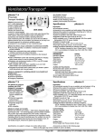
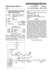
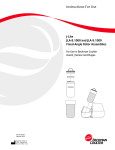
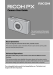
Operation Manual
S168-547-001CPAP
Rev. C
St. Louis, MO 63110
Phone 314-771-2400
Autovent® 4000CPAP
Pneumatically Powered Ventilator
& CPAP Generator
Models L760CPAP, L761CPAP, L762CPAP, L763CPAP
Table of Contents:
Section
1
2
3
4
5
6
7
7a
7b
8
9
10
11
12
13
14
15
16
Models:
L760CPAP
L761CPAP
L762CPAP
L763CPAP
Description
Product Description
Explanation of Warnings
Explanation of Abbreviations
Specifications
Features
Patient Breathing Circuit
Operating the Autovent
Ventilation
CPAP
Pneumatic Alarms
Electronic Alarms
Electronic Alarm Battery Replacement
Cleaning
Maintenance
Accessories
Warranty
Oxygen Cylinder Depletion Times
Symbols
Page
3
3
3
4
6
7
8 - 11
12 - 14
15
15 16
16
17
17
17
18
19 20
20 - 21
AutoVent4000CPAP (Basic Model)
Autovent 4000CPAP with O2 Blender
Autovent 4000CPAP with O2 Blender and Electronic Alarms
AutoVent4000CPAP Basic Model with Electronic Alarms
CAUTION: Federal law restricts this device to sale by or on the order of a
physician.
CAUTION: The Autovent 4000CPAP should not be used on children with a
weight of 20 kg (44 lbs) or less.
1
1
Product Description:
The Autovent 4000CPAP is a pneumatically powered portable ventilator and CPAP
generator. The Autovent 4000CPAP in Ventilation mode, delivers a time cycled
constant flow breath. The inspiratory time is constant and the breath volume is
varied by changing the flow rate into the patient. Various breaths per minute are
achieved by varying the expiratory time.
The AutoVent CPAP models have all the functionality of the Autovent 4000 plus the
added function of CPAP. The CPAP function delivers Continuous Positive Airway
Pressure to the spontaneously breathing patient and is used in place of, and not in
conjunction with, forced ventilation.
The Autovent 4000CPAP is intended to be used as a gas powered emergency
ventilator which, in ventilation mode, is designed to provide emergency respiratory
support by means of a face mask or tube inserted into the patient s airway.
2
Explanation of Warnings:
Warning: Potential injury to the patient or operator exists.
Caution: Potential damage to the ventilator, breathing circuit or other equipment may
result.
Warnings and cautions should be read and understood before operating the
Autovent.
3
Explanation of Abbreviations:
Tv
BPM
It
Psi
CPAP
cm H2O
Kpa
Ml
LPM
Mm
LED
CPR
LPA
HPA
Tidal Volume
Breaths per Minute
Inspiratory Time
Pounds per Square Inch
Continuous Positive Airway Pressure
Centimeters of Water
kilopascal
Milliliters
Liters per minute
Millimeters
Light emitting diode
Cardio Pulmonary Resuscitation
Low pressure alarm
High pressure alarm
2
4
Specifications:
Specifications:
Gas Supply Pressure: 280 kPa (40.6 psi) to 600 kPa (87.0 psi) Oxygen DISS
Breaths per Minute (BPM): Accuracy: ±10%
BPM Range: 1 sec Inspiratory Time = 8 to 30
BPM Range: 2 sec Inspiratory Time = 8 to 20
Tidal Volume (Tv): Accuracy: ±10% with 100% Oxygen
Tidal Volume Range 1 Second Inspiratory Time = 200 ml to 600 ml
Tidal Volume Range 2 Second Inspiratory Time = 400 ml to 1200 ml
Inspiratory Time (It): Accuracy: ±10%
1 second or 2 second selection
Safety Pressure Relief: Adjustable from 20 to 80 cm H2O ±10%. The 60 cm H2O
mark is a maximum regardless of setting.
Low Source Gas Alarm: Activates at 275 to 262 kPa (40 to 38 psi) source
pressure.
Electronic Alarms:
High Airway Pressure Alarm Range 15 to 80 cm H2O
High Airway Pressure Alarm Accuracy 5 %
Low Airway Pressure Alarm Range 0 to 30 cm H2O
Low Airway Pressure Alarm Accuracy 5 %
Alarm Sound Level is greater than 60 decibels
Battery Life: Greater than 40 hours at room temperature
Oxygen Inlet Filter: 65 Micron sintered bronze
Burst Pressure: 250 psig (1724 kPa) minimum
Leakage: The unit shall be designed so that oxygen is not allowed to leak through
any seals or fittings.
Gauge: 0-100 cm H2O (0
the actual reading)
9.8 kPa) accuracy ±(2% of the full scale reading +8% of
Inspiratory and Expiratory Resistance: 5 cm H2O (.5 kPa) maximum
Inadvertent PEEP: < 2 cm H2O
Inadvertent Continuing Expiratory Pressure: < 2 cm H2O
3
Dead Space: 14.8 ml
Peak Inspiratory Flow: 100 LPM for 2 seconds
Pressure for Initiation of Breath: -2 cm H2O maximum
Oxygen Blending: 65% ±12% oxygen with blender
CPAP Range: 4 to 20 cm H20
CPAP Airway Pressure Control: The airway CPAP pressure is controlled to within
+/- 2 cm H20 for all treatment CPAP pressures with inhalation / exhalation flows up to
70 lpm. The airway CPAP pressure is controlled to within +/- 3 cm H20 for all
treatment CPAP pressures with inhalation / exhalation flows between 70 and 100
lpm.
Weight: L760CPAP = 2.35 kg (5.187 lb)
L762CPAP = 2.81 kg (6.20 lb)
L761CPAP = 2.57 kg (5.68 lb)
L763CPAP = 2.67 kg (5.88 lb)
Size: L760CPAP = L761CPAP = 73.6 x 203 x 244 mm (2.9 x 8.0 x 9.6 inches)
L762CPAP = L760CPAP = 73.6 x 241.3 x 244 mm (2.9 x 9.5 x 9.6 inches)
Operating Conditions: -18 to 50°C (0 to 122°F)
Storage Conditions: -40 to 60°C (-40 to 140°F)
Shipping Conditions: -40 to 60°C (-40 to 140°F)
Latex Free: This product does not contain latex.
4
5
Features:
18
17
16
15
14
13
19
12
20
21
11
1
10
2
9
3
8
4
7
5
6
Item #
1
2
3
4
5
6
Description
Tidal Volume Control
Inspiratory Time Control
BPM Control
Oxygen Inlet
Low Source Gas Indicator
Manual Breath Button
Item #
12
13
14
15
16
17
7
O2 Concentration Selector
18
8
9
Airway Pressure Gauge
Adjustable Airway Pressure
Relief
Anti-Suffocation Valve
Patient Circuit Connection
19
20
Description
Patient Airway Pressure Line
CPAP Control Knob
Alarm Module On/Off
Alarm Module Battery Status
Low Source Gas Alarm LED
High Airway Pressure Alarm
Adjustment and LED
Low Airway Pressure Alarm
Adjustment and LED
Alarm Silence Button
Ventilation Mode Switch
21
Blender Ambient Air Filter
10
11
5
•
6 Patient Breathing Circuit
The AutoVent 4000CPAP uses a breathing circuit that allows the user to switch
between ventilation mode and CPAP without having to change breathing circuits.
The breathing circuit consists of a patient valve, corrugated hose (36 in) and a patient
airway pressure line. The patient valve has been designed with a 22 mm OD patient
port to fit a standard mask and a 15 mm ID patient port to fit the standard
endotracheal tube.
The patient valve contains a pressure balance diaphragm and a one way check
valve. The breath being delivered by the Autovent 4000CPAP is delivered through
the corrugated tube to the patient valve. The breath passes through the one way
check valve and is diverted to the patient. Prior to the check valve, a portion of the
breath is diverted to the top side of the balance diaphragm. This action keeps the
exhaust port of the patient valve closed during breath delivery and CPAP operation.
Once the breath is delivered, the top of the diaphragm is vented and the patient can
exhale. In the case of CPAP operation, the top of the diaphragm is kept at CPAP
pressure level and anytime the patient side of the diaphragm exceeds the CPAP
level, the diaphragm lifts and exhausts the patients airway.
6
7a
Operating the Autovent: ( Ventilation)
Warning: This device should only be operated by qualified personnel
under approved medical direction.
Warning: Use only as directed. Improper usage or unauthorized
modification of this product may result in user or patient injury.
• Set the Ventilation Mode switch to Auto Ventilation mode.
In the ventilation mode, the three breath control knobs are active and the patient will
receive a ventilation cycle based on the setting of the three controls (BPM, Inspiratory
Time, Tidal Volume). In addition, the Blender control and the Manual breath control
are also active.
• Connecting to an Oxygen Source:
Located on the left side of the Autovent and marked with an arrow is a diameter index
safety system (DISS) fitting. Connect a 50 psi oxygen source with a minimum of 40
LPM flow capacity to this fitting.
Warning: Proper tidal volumes may not be provided with a gas source
not meeting the specified requirements on page 4.
Warning: This device operates with medical gases under pressure,
including oxygen. Do not use this device while smoking or near open
flames. Do not use on this device or operate near flammable materials.
Caution: In order to provide optimal performance, check all gas
supplies to assure only clean, dry gas is used, free of contaminants
and/or liquids.
The gas source may also be a high flow air/oxygen blender meeting the flow and
pressure requirements. Use only the 100% oxygen setting on the Autovent, if using
an external blender.
•
Connecting the patient breathing circuit:
Caution: Due to the dual functionality of the Autovent 4000CPAP, use only the
recommended breathing circuit. The correct ventilator breathing circuit must be
used. Using the incorrect breathing circuit may result in the unit not functioning
properly.
Located on the right side of the unit is a 22 mm connection for a patient breathing
circuit and a connection for the patient airway pressure line. Install the corrugated
tubing over the 22 mm connector so that it is on securely. Install the small airway
pressure line over the connecting fitting. Both tubing will not pull off easily when
properly installed.
• Select the proper inspiratory time:
The Autovent 4000CPAP has the options of a 2 second inspiratory time (this is
used on adults with tidal volume requirements of more than 600 ml) and a 1 second
7
inspiratory time (this is used on children or adults). Turn the Inspiratory time knob to
the desired selection.
This function operates in the Auto Ventilation mode only.
• Select the desired Breaths per Minute BPM:
The Autovent 4000CPAP has a BPM range of 8 to 15 with a 2 second inspiratory
time and a BPM range of 8 to 30 with a 1 second inspiratory time.
The American Heart Association Guidelines 2005 recommend a BPM rate of 8 to 12
for an adult and 12 to 20 for a child. These are recommendations and you should
always follow your physicians or medical directors instructions.
This function operates in the Auto Ventilation mode only.
• Select the desired Tidal Volume:
The AutoVent 4000 provides a Tidal Volume range of 200 600 ml at an inspiratory
time of 1.0 sec. and 400 1200 ml at an inspiratory time of 2.0 sec.
• Verify the Pressure Relief Setting:
This unit has a pressure relief range of 20 to 80 cm H2O. The 60 cm H2O setting is
a maximum regardless of vent settings. The pressure relief setting will vary slightly
with tidal volume setting. Always verify the pressure relief pressure after the vent
settings have been selected. To check the actual relief pressure, block the end of
the ventilator breathing circuit and observe the reading on the airway pressure
gauge. This will be the maximum airway pressure. You should hear an audible
alarm as this maximum pressure is reached.
Warning: Preset tidal volumes may not be delivered when the
maximum pressure limit is reached. Inspiratory times will remain
constant, however no additional tidal volume will be delivered after the
pressure limit is reached.
• Select the desired Gas Mixture: (Models L761 and L762 only)
On models equipped with a blender you can select 100% oxygen or a 65% Oxygen
gas supply. On the 65% oxygen setting the ventilator uses a venturi blending system
to mix ambient air with the medical oxygen source.
This function operates in the Auto Ventilation mode only.
Warning: Do not use the 65% Air/Oxygen mixture in areas where the
ambient air is not safe for breathing.
• Connect the patient breathing circuit to the Patient:
The patient breathing circuit has been design to fit with an oxygen mask (22 mm
outside diameter) or endotracheal tube (15 mm inside diameter). Follow the
established guidelines for maintaining the patient s airway.
• Verify the patient is receiving good ventilation:
Once the patient is connected to the ventilator the patient should be observed to
make sure they have adequate chest rise and fall. The chest rise should be even
8
and should return to a normal position. If the patient does not have adequate chest
rise check the tidal volume setting, patient connections and examine the patient for a
possible obstruction of the airway or other injury. The patient should be monitored to
make sure they are receiving proper ventilation.
The airway pressure gauge should be observed to make sure the patient is receiving
adequate positive pressure ventilation. If the gauge reading is low during the delivery
of a breath and the chest rise is also low, check the tidal volume setting, patient
connections and examine the patient for a possible obstruction of the airway or other
injury. The gauge reading should also be observed to make sure it is not too high.
Common numbers used in practice are a maximum of 20 cm H2O for and
unprotected airway and 30 cm H2O for a protected airway. Higher pressures may be
required based on the patient s condition and you should always follow the
physician s instructions. A high reading with pressure limit alarm may indicate a
blocked airway or a stiff lung.
• Spontaneous Breathing by the Patient:
Should the patient begin to breathe spontaneously the Autovent 4000CPAP will
sense this breath and deliver the set tidal volume at the set inspiratory rate. The
breath timing will be reset based on the selected BPM rate. For example, if 10 BPM
was selected the next breath will be delivered 6 seconds after the start of the
spontaneous breath.
This function operates in the Auto Ventilation mode only.
The gas flow rate to the patient during a spontaneous breath is based on the tidal
volume selection as shown in the following table. Should the patient demand exceed
the gas flow rate, the addition demand will be supplied by ambient air. Ambient air is
pulled in through an anti-suffocation valve located in the breathing circuit connection
fitting.
Tidal Volume Setting
It = 1 second It = 2 second
200
400
300
600
400
800
500
1000
600
1200
Flow (LPM)
12
18
24
30
36
9
Warning: Should a mechanical problem develop or the patient appears
to be experiencing difficulty breathing while connected to the unit,
disconnect the unit immediately and ventilate by other means.
Warning: Units that have been stored at temperatures below 32°F
(0°C) may have a 20% shift in settings when they are operated at these
low temperatures. The readings will return to normal when the unit
warms up. Always monitor patients when the unit is used under these
conditions.
•
Manual Breaths:
Manual breaths may be delivered using the manual breath button. Each time this
button is pushed the ventilator will deliver one breath with the selected inspiratory
time and tidal volume. This button can be used to deliver breaths during CPR. If this
button is pushed during automatic ventilation, the ventilator will deliver the breath and
then continue to deliver automatic breaths based on BPM rate selected. For example
if you were delivering 10 BPM with a 2 second inspiratory time the manual breath
button would trigger a breath to be delivered when pushed. This breath would have
a 2 second inspiratory time, followed by a 4 second expiratory time. Automatic
ventilation would then continue based on the 10 BPM setting.
This button should be pushed and released as soon as the desired breath
starts. If the button is held down longer than the inspiratory time the tidal volume will
be based on the time the button is held down and will exceed the set value. The
pressure relief may trigger if this happens.
Caution: Holding the manual breath button down for more than 1
second may trigger multiple breaths or increase the delivered tidal
volume.
This function operates in the Auto Ventilation mode only.
10
7b Operating the Autovent: ( CPAP )
Warning: This device should only be operated by qualified personnel
under approved medical direction.
Warning: Use only as directed. Improper usage or unauthorized
modification of this product may result in user or patient injury.
Warning: The CPAP function delivers Continuous Positive Airway
Pressure to the spontaneously breathing patient and is used in place of,
and not in conjunction with, forced ventilation.
•
Switch the Ventilation Mode switch to the CPAP mode.
When the Operation Mode switch is set to the CPAP mode, the three breath
setting controls , (BPM, Inspiratory Time, Tidal Volume), as well as the Manual
Breath and Oxygen Concentration switch are no longer active. Changing these
controls will have no effect on the CPAP operation.
• Connecting to an Oxygen Source:
Located on the left side of the Autovent and marked with an arrow is a diameter index
safety system (DISS) fitting. Connect a 50 psi oxygen source with a minimum of 40
LPM flow capacity to this fitting.
Warning: This device operates with medical gases under pressure,
including oxygen. Do not use this device while smoking or near open
flames. Do not use on this device or operate near flammable materials.
Caution: In order to provide optimal performance, check all gas
supplies to assure only clean, dry gas is used, free of contaminants
and/or liquids.
The gas source may also be a high flow air/oxygen blender meeting the flow and
pressure requirements. The onboard AutoVent 4000CPAP blender is inactive when
the unit is in the CPAP mode. Changing the oxygen concentration of the onboard
blender will have no effect of the oxygen concentration being delivered to the patient
during CPAP function.
•
Connecting the patient breathing circuit:
Caution: Due to the dual functionality of the Autovent 4000CPAP, use only the
recommended breathing circuit. The correct ventilator breathing circuit must be
used. Using the incorrect breathing circuit may result in the unit not functioning
properly.
Located on the right side of the unit is a 22 mm connection for a patient breathing
circuit and a connection for the patient airway pressure line. Install the corrugated
tubing over the 22 mm connector so that it on securely. Install the small airway
11
pressure line over the connecting fitting. Both tubing will not pull off easily when
properly installed.
• Airway Pressure Relief Control:
This unit has a used adjustable main airway pressure relief range of 20 to 80 cm
H2O. During CPAP only, the unit also has an active internal 20 cm H20 CPAP
pressure relief that will not allow the set CPAP pressure to exceed 20 cm H20. Due
to the high gas flow rates of CPAP, the main airway pressure relief should be set
higher than potential CPAP pressures (60 cm H2O).
•
Preset the CPAP function prior to patient connection.
o After the patient breathing circuit has been connected to the unit, turn the
CPAP control full counter clockwise (lowest setting).
o Turn on the inlet supply gas.
o Adjust the CPAP control to achieve minimum gas flow.
• Connect the patient breathing circuit to the Patient:
Once the mask has been fitted to the patient, observe the patient and adjust the
CPAP pressure to the desired CPAP pressure. The patient breathing circuit has been
design to fit with an oxygen mask (22 mm outside diameter) or endotracheal tube (15
mm inside diameter). Follow the established guidelines for maintaining the patient s
airway.
• Verify the patient is receiving good ventilation:
Once the patient is connected to the ventilator, the patient should be observed to
make sure they have adequate breathing.
Warning: The CPAP function delivers Continuous Positive Airway
Pressure to the spontaneously breathing patient and is used in place of,
and not in conjunction with, forced ventilation.
The airway pressure gauge should be observed to make sure the patient is receiving
proper CPAP pressure. Always follow the physician s instructions. A high reading
with pressure limit alarm may indicate a blocked airway.
Warning: Should a mechanical problem develop or the patient appears
to be experiencing difficulty breathing while connected to the unit,
disconnect the unit immediately and ventilate by other means.
Warning: Units that have been stored at temperatures below 32°F
(0°C) may have a 20% shift in settings when they are operated at these
low temperatures. The readings will return to normal when the unit
warms up. Always monitor patients when the unit is used under these
conditions.
12
•
8
Pneumatic Alarms:
This ventilator contains several pneumatically operated alarms. These alarms are
the pressure relief and low source gas alarms.
The pressure relief alarm is an audible alarm that is actuated when the safety
pressure relief setting is reached. This alarm indicates that the maximum pressure
setting has been exceeded and that gas has been released to prevent the pressure
from reaching levels above this setting.
Warning: Preset tidal volumes may not be delivered when the
maximum pressure limit is reached. Inspiratory times will remain
constant, however no additional tidal volume will be delivered after the
pressure limit is reached.
Low source gas alarm is an audible and visual alarm that activates when the source
gas pressure drops below 40 to 35 psi. This is an indication that the unit will stop
functioning soon and that the unit may not be delivering proper tidal volumes. This
alarm will first sound only during breath delivery as a first indication and then sound
continuously as the source gas pressure drops.
Warning: Preset tidal volumes may not be delivered when the low
source gas pressure is reached.
•
9
Electronic Alarms: (Models L762CPAP and L763CPAP only)
The optional electronic alarms module will give an audible and visual (flashing light)
for the following alarms:
• Low Source Gas
• High Airway Pressure
• Low Airway Pressure
Low source gas alarm is an audible (intermittent tone) and a visual alarm that
activates when the source gas pressure drops below 40 to 38 psi. This is an
indication that the unit will stop functioning soon and may not be delivering proper
tidal volumes. The alarm will clear when proper source gas pressure is restored for a
minimum of 10 seconds. See low source gas alarm in section 6 for more information.
High airway pressure alarm is an adjustable alarm that will activate if the pressure
exceeds the selected pressure. This alarm operates independently from the
pressure relief alarm. This alarm can be set at a pressure of 15 to 80 cm H2O. This
alarm may be used to monitor a change in the patient s condition such as fluid
collecting in the lungs or a partial obstruction of the airway. This alarm is
automatically cleared when 25 seconds pass without a high airway pressure being
detected. This alarm has a flashing red LED and a continuous audible tone.
The low airway pressure alarm is an adjustable alarm that will activate if the airway
pressure does not exceed a minimum value. A dial is used to set the LPA set point
13
from 0 to 30 cm H2O. The airway pressure must exceed the low pressure set point at
least once every 15 seconds or the LPA LED will turn on and the buzzer will sound
an intermittent tone or beep . The alarm will clear when the airway pressure goes
above the set point. This is used to indicate a potentially insufficient tidal volume or a
patient disconnect.
Alarm Module Battery Indicator LED During normal operations the LED is green
when the unit is on. When the battery reaches a low voltage point (about 2 or 3
hours before the alarm package will stop working) the Battery Indicator will turn
yellow. When the battery reaches an even lower voltage point (about 1hour before
the alarm package will stop working) the Battery Indicator will turn red. The alarm
package does not have to be turned on for the ventilator to operate properly. The
alarm module adds additional monitoring capability.
Silence Button When there is an alarm the user may press the silence button. This
will turn off the buzzer for 110 seconds as long as there are no other alarms.
Pressing this button will not clear the alarm LED s.
•
10
Electronic Alarms Battery Replacement:
Battery Door removed from
back of alarm module.
Keyed Battery Connection
The Electronic Alarms battery is replaced by removing the 2 screws on the battery
door located on the back of the alarm module. This will require a Phillips head
screwdriver. The battery should be removed from the connector by gently prying off
the snaps on the battery connector. The old battery will then be replaced by a new 9
volt alkaline battery. The snaps are keyed for polarity by size and shape. The battery
will go on only one way; do not modify the battery clip to make a battery fit the
connection. Once the battery is installed on the connector turn the slide the battery
and wires back into the battery compartment and replace the battery door.
Turn the alarm module on and verify the battery status light turns green. The low
airway pressure alarm will sound if the airway pressure does not reach the set value
in 15 seconds. The alarm module is now ready for use. Always turn the alarm
module off when not in use. The alarm module does not turn off automatically.
Warning: Do not try and recharge the battery.
14
•
11
Cleaning:
The Autovent 4000CPAP should be cleaned after each use. To clean the Autovent
4000CPAP keep the gas supply hose on the unit to prevent contamination of the
oxygen circuit.
Warning: Cleaning procedures should be performed in an environment
free of oil and petroleum based products.
The Autovent 4000CPAP has been designed to be water resistant but the unit cannot
be submerged or sprayed down for cleaning.
Wipe the unit down with a damp rag containing a mild detergent to remove any
residue from the surface. Once the residue has been removed the unit should be
wiped with isopropyl alcohol or a cold disinfecting solution to kill bacteria. The unit
should then be wiped down with water to remove any film left by the cold disinfecting
solution. Make sure the unit is dry before putting the unit away.
The following is a list of tested cleaning solutions:
1.
2.
3.
4.
Isopropyl Alcohol :
Alconox:
Cetylcide:
Bleach:
70% IPA
1 Tablespoon Alconox to 1 Gallon H2O
2 Tablespoon Cetylcide to 1 Gallon H2O
10% Bleach in H2O
Warning: Do not attempt to clean and re-use single patient ventilation
circuits as loss of performance may occur.
Dispose of single patient use items per local biohazard standards.
The unit should be checked for proper operation before use. This can be done after
cleaning to have the unit ready when needed.
•
12
Maintenance:
The Autovent 4000CPAP contains a dust filter located on the left side of the unit.
This filter cleans the ambient air used in the function of the blender. To replace or
clean the filter, pry the filter cover off. Once the cover is removed the filter can be
removed. Replace the filter into the cover housing and snap the cover back in place.
AutoVent 4000 Check Out Procedure
1. Set the Autovent 4000 to the following settings:
BPM = 10
Inspiratory Time = 2 seconds
Tidal Volume = 800 ml
If you have a CPAP unit you must connect a CPAP vent circuit for testing. You do
not need a vent circuit to test the units without CPAP.
15
2. Connect a 50 psi oxygen source to the unit and it should begin to cycle.
3. Using a watch count the number of breaths delivered in 1 minute (60
seconds). You should have 9 to 11 breaths. The inspiratory time will be 2
seconds and the expiratory time will be 4 seconds.
4. Set the pressure relief to 60 cm H2O and occlude the output fitting or vent
circuit output if used. The pressure on the gauge cannot exceed 60 cm H2O
(it can be lower). You should also hear an audible squeak to signal the
pressure relief has actuated.
5. Unblock the output and push and release the manual breath button and a
breath should be triggered.
Units with the Optional Alarm Package follow steps 6, 7 & 8
6. Set the low pressure alarm to 10 cm H2O and the high pressure alarm to 30
cm of H2O and turn the alarm module on.
7. With the ventilator output open you should get a low pressure alarm in about
15 seconds.
8. After the alarm sounds occlude the ventilator output, the low pressure alarm
should clear and the high pressure alarm will sound. Remove the occlusion
and high pressure alarm will clear in about 25 seconds.
Units with CPAP follow step 9.
9. Occlude the vent circuit output and adjust the CPAP pressure to the maximum
setting by turning the knob clockwise. The max pressure should be
approximately 20 cm H2O. Adjust the CPAP pressure to 10 cm H2O and the
pressure should be stable.
Units with a blender follow step 10.
10. Switch the unit to 65% O2 and verify the unit is still delivering breaths.
All unit follow steps 11 and 12.
11. Turn the source gas off and you should see the low gas indicator turn red
momentarily.
12. Visually inspect the anti-suffocation valve in the ventilator outlet fitting to verify
that it is laying flat against the inside of the fitting.
The Autovent 4000CPAP should be checked for calibration annually.
If problems are noted with this product, contact the Allied Healthcare Products, Inc.
technical support center for assistance at 800-411-5136.
16
•
13
Accessories:
Part Number
800148
800149
L270-220
L535026
•
14
Description
CPAP Ventilator Circuit
Filter, CPAP
Oxygen Regulator
Oxygen Hose 6ft W/ DISS fittings
Qty per Package
6
3
1
1
Warranty:
EU Authorized Representative:
Medizintechnik & Consulting
Effengrube 14
23552 Lubeck, Germany
Tel: +49-451-8090-4200
Fax: +49-451-8090-4231
17
15
Oxygen Cylinder Depletion Times:
These times are approximate and assume full cylinder capacity and .5 liters per
minute usage for the pneumatic module. Always monitor the cylinder pressure and
low pressure alarm to make sure you do not run out of oxygen.
E Cylinder
Capacity =
682
Breaths per Minute
1200
1000
800
600
500
400
300
200
8
9
10
12
14
15
18
20
22
24
26
28
30
67
80
98
127
149
180
225
293
60
72
88
115
135
163
206
274
54
65
80
104
123
149
189
256
46
54
67
88
104
127
163
225
39
47
58
76
90
111
143
200
37
44
54
72
85
104
135
189
60
72
88
115
163
54
65
80
104
149
50
59
73
96
137
46
54
67
88
127
42
50
62
82
119
39
47
58
76
111
37
44
54
72
104
Tidal
Volume
Jumbo D Cylinder
Capacity =
637
Breaths per Minute
1200
1000
800
600
500
400
300
200
8
9
10
12
14
15
18
20
22
24
26
28
30
63
75
92
119
139
168
210
274
56
67
82
107
126
152
192
256
51
61
75
97
115
139
177
239
43
51
63
82
97
119
152
210
37
44
54
71
85
104
134
187
34
41
51
67
79
97
126
177
56
67
82
107
152
51
61
75
97
139
46
55
68
89
128
43
51
63
82
119
40
47
58
76
111
37
44
54
71
104
34
41
51
67
97
Tidal
Volume
18
D Cylinder
Capacity =
414.6
Breaths per Minute
1200
1000
800
600
500
400
300
200
8
9
10
12
14
15
18
20
22
24
26
28
30
41
49
60
77
91
109
137
178
37
44
54
70
82
99
125
166
33
39
49
63
75
91
115
155
28
33
41
54
63
77
99
137
24
29
35
46
55
67
87
122
22
27
33
44
52
63
82
115
37
44
54
70
99
33
39
49
63
91
30
36
44
58
84
28
33
41
54
77
26
31
38
50
72
24
29
35
46
67
22
27
33
44
63
Tidal
Volume
•
16
Symbols:
Degree of protection against electric shock: Type BF
Caution, Consult accompanying documents
% Relative Humidity: 0 to 90%
Temperature Range: -20°F to 140°F
On/Off
§
§
§
§
Internally powered device
IP20 degree of protection against ingress of water
Equipment not suitable for use in presence of a flammable anesthetic mixture with
air or with oxygen or nitrous oxide
Suitable for continuous operation
This equipment has been tested and found to comply with the EMC limits for the Medical
Device Directive 93/42/ECN (EN 55011 and EN 60601-1-2). These limits are designed to
provide reasonable protection against harmful interference in a typical medical installation.
The equipment generates, uses and can radiate radio frequency energy and, if not installed
19
and used in accordance with these instructions, may cause harmful interference to other
devices in the vicinity. However, there is no guarantee that interference will not occur in a
particular installation. If this equipment does cause harmful interference with other devices,
which can be determined by turning the equipment off and on, the user is encouraged to try to
correct the interference by one or more of the following measures:
§ Reorient or relocate the receiving device
§ Increase the separation between the equipment
§ Connect the equipment into an outlet on a circuit different from that to
which the other device(s) is connected.
Consult the manufacturer or field service technician for help
20