1
Benthic and Resistivity
Sensors (BARS)
User’s Manual
Designed and Built for:
Marv Lilley (University of Washington)
Canadian Neptune Project
Designed and Built by:
Ocean. Engineering Services
University of Washington
Rex Johnson
Randy Fabro
Tor Bjorklund
Built: July, 2010
Last Update: July 18, 2012
---------- TABLE OF CONTENTS ----------
Section 1 ................. Overall System Description
Data Format
Specifications
Section 2 ................. Operating Instructions
A. Preparations for Deployment
B. User Operation Notes
C. Scientific Event Detection
D. Troubleshooting Notes
E. Post Cruise Procedures
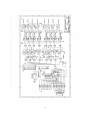
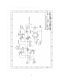
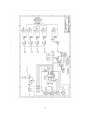
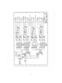
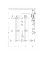
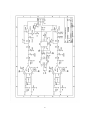
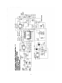
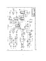
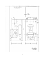
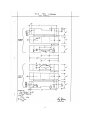
Section 3 ................. Schematics
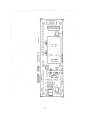
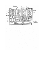
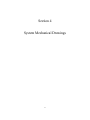
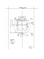
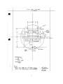
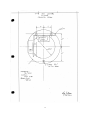
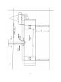
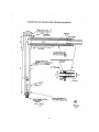
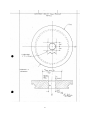
Section 4 ................. Mechanical Drawings
Section 5 ................. Notes
2
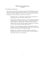
Section 1
Overall System Description
3
4
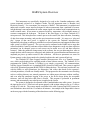
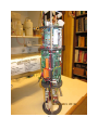
BARS System Overview
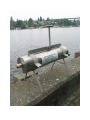
This instrument was specifically designed to be used on the Canadian underwater cable
system commonly referred to as Neptune Canada. The full instrument name is “Benthic And
Resistivity Sensors”. For convenience, the acronym is “BARS”. This instrument is a sophisticated
underwater scientific sensor interface designed to take measurements from a multitude of sensors
in hydrothermal vents and translate the sensor output signals via standard serial communications in
useful scientific units. It has sensors to measure resistivity, temperature, eH (oxidizable nature of
seawater components) & hydrogen. The heart of the data logger is an Onset Tattletale 8V2
microprocessor. This microprocessor controls power to the sensors, the data collection, formatting
of data, data output streaming, and provides user interaction as needed. It is setup as a “plug and
play” system in that once power is applied to the system, the Tattletale microprocessor
automatically takes data according to preloaded user selected parameters and outputs the data to the
cable system via RS422 protocol. The user can send a command to the BARS unit to stop data
collection (double Control-S) and enter a Menu Mode where diagnostics can be run, data collection
parameters can be changed, power to each sensor can be turned on or off, and data collection
restarted. Under the parameter change menu in the software, the user can determine how often to
sample the data, which sensors are energized, and whether the system Metadata and Parameters are
outputted pm power up and/or restart of data collection. All the user parameters are stored in
Eprom memory so they do not need to be reloaded each time the unit is powered back up.
The Tattletale 8V2 Data Logger/Controller Microprocessor lives in a Titanium pressure
case, which can be deployed for extended periods of time without concern. The Tattletale 8V2 is
programmed in TxBasic (Version 5). TxBasic is very simple, yet powerful. All communications
with the Logger/Controller are via standard RS422 protocol at 9600 baud. This system is supplied
with a fully operational program (BARS.TXB) for taking the data. This software provides the user
with the ability to select parameters, do diagnostics, and collect data based on the operator’s
selected parameters, all with user friendly menus. This program also does automatic error checking
such as verifying that any user entered parameters are within proper tolerances without conflicts,
and even stops the automatic logging if the power to the device drops below the acceptable
tolerance, since all data below that point is invalid. This program is preloaded in permanent
memory and automatically runs when power is applied to the system.
The system is designed to be operated on the Canadian underwater cable system. It expects
the input power to be 15 volts but it can operate properly with an input voltage as low as 13 volts or
as high as 30 volts dc. The system outputs serial data to the cable system using RS422 protocol at
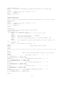
user defined time intervals from 15 seconds to 60 minutes. An example of the output data is shown
on the next page with the formatting of that data shown on the following page.
5
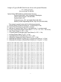
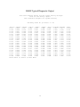
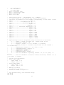
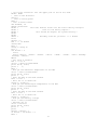
Sample of Typical BARS Data Stream shown with optional Metadata
(12 words per burst)
(See next page for details)
System Name: BARS (Benthic and Resistivity Sensors)
System Owner: Marv Lilley, University of Washington
Owner Contact Phone #: 206-543-0859
System Serial #: 001
Software Version 1.86, Last Update March 28, 2012
Made by Ocean Engineering Service, July 2010 (206-543-9688)
This system is presently setup with the following parameters:
1 = Eprom Status (0 means not setup yet, 1 means ready to use)
20 = Cycle Time (Actual time in seconds or minutes)
0 = Minutes or seconds Cycle Time (0 = seconds mode, 1 = minutes mode)
55 = Power Control Word (Power Control Word = 1 + 2 + 4 + 16 + 32 = 55 if all on)
1 = Res Power Status (0 = Off, 1 + On)
1 = Thermocouple & Hydrogen Amp Power Status (0 = Off, 1 + On)
1 = eH Amp Power Status (0 = Off, 1 + On)
1 = Hydrogen Sensor Power Status (0 = Off, 1 + On)
1 = Reference Temperature Power Status (0 = Off, 1 + On)
0 = Metadata Print Status on Power Up (0 = No print on Power up, 1 = Print)
0 = Metadata Print Status on Restart Data Collection (0 = No print, 1 = Print)
0.065
0.066
0.067
0.067
0.067
0.067
0.068
0.067
0.068
0.067
0.065
0.067
0.066
0.068
0.067
0.066
0.068
0.065
0.065
0.338
0.337
0.337
0.337
0.335
0.336
0.335
0.337
0.334
0.335
0.337
0.338
0.336
0.335
0.337
0.337
0.334
0.338
0.337
1.660
1.660
1.660
1.659
1.662
1.659
1.660
1.660
1.660
1.665
1.657
1.657
1.654
1.660
1.659
1.657
1.657
1.658
1.659
0.123
0.122
0.123
0.122
0.120
0.123
0.121
0.122
0.121
0.120
0.123
0.122
0.125
0.121
0.123
0.123
0.121
0.123
0.123
0.637
0.639
0.638
0.642
0.638
0.638
0.641
0.639
0.639
0.639
0.637
0.639
0.639
0.641
0.639
0.639
0.642
0.637
0.637
3.201
3.200
3.200
3.200
3.199
3.198
3.198
3.199
3.198
3.199
3.200
3.199
3.199
3.197
3.199
3.199
3.196
3.200
3.200
1.994
1.993
1.993
1.993
1.995
1.993
1.994
1.993
1.994
1.995
1.994
1.993
1.993
1.994
1.994
1.994
1.994
1.994
1.995
1.877
1.877
1.878
1.877
1.875
1.878
1.876
1.878
1.874
1.874
1.876
1.877
1.878
1.876
1.878
1.878
1.876
1.877
1.877
6
3.53
3.53
3.51
3.53
3.57
3.51
3.55
3.51
3.59
3.59
3.55
3.53
3.51
3.55
3.51
3.51
3.55
3.53
3.53
1.284
1.283
1.283
1.283
1.284
1.283
1.283
1.283
1.284
1.282
1.283
1.283
1.283
1.283
1.284
1.284
1.283
1.283
1.283
318.1
317.8
317.8
317.8
318.1
317.8
317.8
317.8
318.1
317.6
317.8
317.8
317.8
317.8
318.0
318.0
317.8
317.8
317.8
9.1
9.1
9.1
9.1
9.1
9.1
9.1
9.1
9.1
9.1
9.1
9.1
9.1
9.1
9.1
9.1
9.1
9.1
9.1
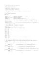
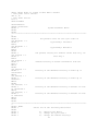
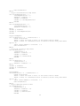
BARS Data Format
BARS Outputted Data Format using BARS.TXB Program:
The following is the Data Format for each burst: (12 Words/burst). The time between bursts is
user selectable from 15 seconds to 60 minutes.
Word 1 ………..………………….... Resistivity/5 (See Note 1)
Word 2 ………..…………………… Resistivity X1 (See Note 1)
Word 3 …………..………………… Resistivity X5 (See Note 1)
Word 4 …………..………………… Hydrogen/5 (See Note 1)
Word 5 …………..………………… Hydrogen X1 (See Note 1)
Word 6 …………..………………… Hydrogen X5 (See Note 1)
Word 7 ……………..……………… Eh Sensor (See Note 1)
Word 8 …………….………………. Reference Temp Volts (1) (2)
Word 9 ………….…………………. Reference Temp Deg C
Word 10 …..………………………. Resistivity Temp Volts (1) (3)
Word 11 ……..……………………. Resistivity Temp Deg C
Word 12 …………………………... Battery Voltage (See Note 1)
Notes:
1. This data is outputted in volts.
2. The Reference Thermistor voltage must be translated into Degrees C based on the
tables included in the NOTES and the SCHEMATICS sections of this manual. The
Program BARS.TXB uses the equation: Tm(deg C) = 27.50133 – 17.2658*V +
15.83424/V (V = Tm volts)
3. The Thermocouple voltage must be translated into Degrees C based on the tables
included in the NOTES and the SCHEMATICS sections of this manual. The
Program BARS.TXB uses the equation: Tc(deg C) = (244970*V)/1000 (V = Tc
volts). The Final Corrected Temperature = Tm + Tc. The outputted voltage is just
that of the sensor. The outputted temperature has been corrected with the reference.
7
BARS Specifications
Main Control Unit & Data Logger:
Microprocessor ..............................……….....
Tattletale 8V2
Operating System ………………………….. TxBasic Version 5.0
Total Data Storage ..............................……....
512M Bytes
12 Bit A/D Converter ...........................……. 8 Channels of 0-4.096 volts
Clock Stability ......................................……. +/- 20PPM (+/-1 Min/Mon)
Resistivity Sensor:
Manufacturer ….…….................................... UW-Physics
Electronics Manufacturer …………………. Ocean Eng. Services
Output ……….……………………………. 0 - 4 volts
Resistivity Temperature Sensor:
Sensor Manufacturer ….……......................
Probe Manufacturer ……………………….
Model Number …………………………….
Type ………………………………………
Range .................................................………
Omega Engineering (Custom)
Ocean. Engineering Services
CATi-116U-24
K Thermocouple
0-400 C
Reference Temperature Sensor:
Sensor Manufacturer ………………………
Model Number …………………………….
Characteristics ……………………………..
Usable Range ………………………………
YSI
44031
10K Ohms @ 25C
0 to 30 C
Hydrogen Sensor:
Probe Manufacturer ….……........................... UW-Physics
Sensor .................................................……… Entran EPXN-V03*-15P-/Z1
Sensor Output ……..………………………. 0 – 69.88 mV FS equals 0-15 PSI
Electronic Gain …………………………… 10
Usable Range …………………………….. 0-4.096 volts
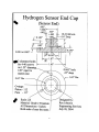
Pressure Housing …………………………. Titanium (1.65”Dia x 3.5”)
Depth Rating ……………………………… 22732 PSI (50604 FT)
Power ……………………………………... 4.096V @ 0.25 ma
eH Sensor:
Probe Manufacturer ………………………. Ko-ichi Nakamura
Sensor Output …….………………………. +/-0.5 volts
Electronically shifted and amplified to …… 0 to 4 volts
8
BARS Specifications
(Continued)
Logger Pressure Case:
Material ...............................................…….
Outside dimensions ..............................……
Weight in Air (With Electronics) .........……
Weight in H2O (With Electronics) .......……
Collapse Pressure ................................…….
Titanium 6AL4V
5.0" Diameter, 19.5" Long
31.6 Lbs.
15.6 Lbs.
19656 PSI (43755 FT)
System Power Consumption: (All sensors turned on)
Logger Dropout Voltage ....................…….. 12 volts
System Maximum Voltage ……………….. 30 volts
Peak current requirement ………………… 85 ma
Waiting to take next burst of data ………… 52 ma
Taking A/D Data (5 seconds/cycle) .………. 52 ma
Formatting Data (5 seconds/cycle) ………… 77 ma
Sending Data (1 second/cycle) ………..…... 85 ma
Menu Mode ………………….……………. 50 ma
System Power Control:
Control Line 0 …………....................….…..
Control Line 1 ……………………………..
Control Line 2 ………………………….….
Control Line 4 ………………………….….
Control Line 5 ……………………………..
Res Electronics (+9 v)
Instrumentation Amp (+9 v)
Iso Amp (+9 v)
Hydrogen Sensor (+Vref)
Reference Temperature (+Vref)
System Communications:
Hardware Port ……………………………… RS422
Baud Rate …………………………………. 9600 Baud
9
BARS Specifications
(Continued)
Tattletale I/O Assignments:
Digital I/O:
TPU0 ......................................……… Analog Power Control (1 = On)
TPU1 ......................................……… Mux Strobe
TPU2 ......................................……… SDO Latch
TPU3 ......................................……… Not Used
TPU4 ......................................……… Freq. Input (Period/Count)
TPU5 ......................................……… S Clock
TPU6 ......................................……… Not Used
TPU7 ......................................……… Not Used
TPU8 ......................................……… SDO Data
TPU9 ......................................……… D-Out #1 (0 = On)
TPU10 ....................................……… D-Out #2 (0 = On)
TPU11 ....................................……… D-Out #4 (0 = On)
TPU12 ......................................…….. Not Used
TPU13 ......................................…….. RS232 Out#2 (USEND)
TPU14 ....................................……… RS232 In#2 (UGET)
TPU15 ......................................…….. Not Used
Analog I/O (12 Bits):
A0 …………………………………
A1 …………………………………
A2 …………………………………
A3 …………………………………
A4 …………………………………
A5 …………………………………
A6 …………………………………
A7 …………………………………
Mux0 ……………………………...
Mux1 ………………………………
Mux2 ………………………………
Mux3 ………………………………
10
Resisitivity/5
Resisitivity X1
Resistivity X5
Hydrogen/5
Hydrogen X1
Hydrogen X5
Eh Sensor
Mux Input
Reference Temperature
Resistivity Temperature
Battery Voltage/10
Not Used
Section 2
Operating Instructions
11
12
BARS Operating Instructions
A. Preparations for Deployment:
1. Since this device lives in a titanium pressure case, which is very durable and the
microprocessor controller is programmed to be “Plug and Play”, one only needs to plug the
sensors into the unit (clean and grease each connector) and attach the interconnecting cable
that goes to the underwater cable system. Be sure to use the locking sleeves on each
connector. There are no other necessary preparations.
2. If for some reason, you need to open the pressure case, remove the end cap with all the
connectors first. To do this remove the 4 small screws that hold the multi-connector end cap
to the pressure case. Then use fiberglass wedges to remove the endcap itself (NEVER USE A
SCREWDRIVER!). The end cap is connected to the internal electronics through several
connectors. Unplug them so the end cap is free. Next remove the opposite end cap that only
has one connector using the same method. This end cap is also connected to the internal
electronics with a connector. Once it is unplugged, this end cap is free. Then you can slide
the electronics out of the case.
3. To talk to this instrument directly with the short interface cable for testing purposes, use a
communications program like Onset’s TxTools software. Connect your computer’s RS232
serial port to the interface cable connector (DE9). Start TxTools on your computer. The first
time you start TxTools, you will have to set the serial port configuration (9600 Baud). Apply
15 volt power to the interface cable’s banana connectors. After a few seconds, data will
stream out of the system in 12 word bursts. The default time between bursts is 20 seconds, but
it can be set to anything between 15 seconds and 60 minutes.
4. To access diagnostics and user options, enter the 2 key command “Control-S”. When the unit
receives this command, it acknowledges it by sending back a line feed and a carriage return.
When you see this, you have about ½ second to send another “Control-S” command, or it will
be ignored. This double “Control-S” technique prevents false commands from stopping the
data collection. If the unit is in data collection mode which typical lasts for about 6 seconds at
the time that the system is setup to take data, it will ignore the “Control-S” command, so it is
important to send this command when the unit is not taking data. When the “Control-S”
command is properly sent and received, the microprocessor will display a Main Menu of
options as follows:
Select one of the following functions:
0). Reprint Time and this Menu
1). Restart Data Collection
2). Change Data Collection Parameters
3). System Diagnostics
4). Set the system clock
5). Control Power to Sensors
6). Provide information on this system
7). Exit this program
13
BARS Operating Instructions
(continued)
5. When you enter the Main Menu mode, if you have not already set the system clock, you will
see a notice to set it. This is done through option #4. After you have set the proper Date and
Time, the current system time will be displayed along with the menu options.
6. Option #2 on this menu enables the user to change parameters, including the time between each
burst (Cycle Time), whether the unit outputs only the data or goes into a verbose mode to
assist debugging any problems remotely, and whether to enable or inhibit the output of the
Metadata on power up and/or on restart of data collection. This submenu also has an option to
force all the system parameters back to the default settings as shown in the system
specifications. Lastly, this menu has an option to output all the system Metadata as a
convenience.
7. Option #3 is a System Diagnostics to verify that everything is functioning correctly. See the
typical diagnostic output data on the next page.
8. As already mentioned above, Option #4 enables the user to set the system clock.
9. Option #5 allowed the user to remotely turn power on/off to each selected sensors. This can be
useful for diagnostics for example it there is a suspected ground loop due to a sensor leak or
failure. It can also be used to turn off a damaged sensor that due to the ground loop currents or
other problems, it is affecting all the other data.
10. Option #6 provides identification and contact information on this unit. The exact format is as
follows:
System Name: BARS (Benthic and Resistivity Sensors)
System Owner: Marv Lilley, University of Washington
Owner Contact Phone #: 206-543-0859
System Serial #: 001
Software Version 1.86, Last Update March 28, 2012
Made by Ocean Engineering Service, July 2010 (206-543-9688)
This system is presently setup with the following parameters:
1 = Eprom Status (0 means not setup yet, 1 means ready to use)
20 = Cycle Time (Actual time in seconds or minutes)
0 = Minutes or seconds Cycle Time (0 = seconds mode, 1 = minutes mode)
55 = Power Control Word (Power Control Word = 1 + 2 + 4 + 16 + 32 = 55 if all on)
1 = Res Power Status (0 = Off, 1 + On)
1 = Thermocouple & Hydrogen Amp Power Status (0 = Off, 1 + On)
1 = eH Amp Power Status (0 = Off, 1 + On)
1 = Hydrogen Sensor Power Status (0 = Off, 1 + On)
1 = Reference Temperature Power Status (0 = Off, 1 + On)
0 = Metadata Print Status on Power Up (0 = No print on Power up, 1 = Print)
14
0 = Metadata Print Status on Restart Data Collection (0 = No print, 1 = Print)
11. The last option (#7) is necessary, since it is the only way to stop the program. If this option is
selected, the following text comes up:
Are you really sure that you want to stop this program?
Enter 1 for Yes, 0 for No Æ
If the number 1 is entered, the program stops and the TxBasic Prompt will come up. If the
number 0 is entered, you are returned to the Main Menu. Do not stop this program unless you
really want to and understand the consequences.
12. To restart data collection, select option #1 on the Main Menu.
13. All the submenus that have lists of user’s options can accept commands from 0 to 9. If you
enter the number “9”, while in any of these submenus, the program jumps back to the Main
Menu.
14. This system is also setup to ignore random commands whether in the data collection mode or
one of the Menu Modes. In addition, if the user enters a value outside the acceptable range of
the requested parameter, the program will respond with a warning and the user will have the
option of inputting a new value.
15
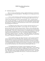
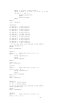
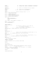
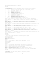
BARS Typical Diagnostic Output
This Test Routine Prints out the actual Analog Voltages
from all the Analog Inputs.
This should be helpful for system testing.
How Many Scans do you want? --> 20
-Res/5- -ResX1- -ResX5- -*H2/5- -*H2X10.131
0.645
3.167
0.044
0.241
0.129
0.646
3.159
0.122
0.621
0.130
0.647
3.168
0.126
0.619
0.132
0.650
3.168
0.129
0.621
0.131
0.646
3.165
0.126
0.621
0.130
0.647
3.184
0.132
0.623
0.131
0.644
3.170
0.127
0.625
0.130
0.646
3.188
0.129
0.622
0.131
0.647
3.170
0.129
0.620
0.133
0.647
3.164
0.126
0.623
0.130
0.647
3.161
0.126
0.622
0.132
0.647
3.163
0.128
0.620
0.129
0.647
3.166
0.130
0.622
0.130
0.646
3.166
0.129
0.620
0.129
0.651
3.166
0.127
0.621
0.132
0.644
3.188
0.127
0.632
0.131
0.646
3.176
0.126
0.624
0.132
0.645
3.159
0.129
0.623
0.131
0.643
3.173
0.128
0.628
0.128
0.646
3.168
0.126
0.621
Press Enter to return to Main Menu.
-*H2X51.448
3.046
3.047
3.046
3.052
3.050
3.051
3.046
3.049
3.046
3.045
3.046
3.048
3.044
3.046
3.050
3.045
3.049
3.047
3.052
16
-*Eh**2.000
2.001
2.000
2.001
2.000
2.001
1.999
2.002
2.000
2.000
2.000
2.000
2.001
2.000
1.999
2.001
2.001
2.002
2.000
1.998
RefTemp
1.875
1.876
1.875
1.871
1.876
1.876
1.871
1.875
1.871
1.875
1.876
1.877
1.874
1.876
1.872
1.873
1.874
1.870
1.874
1.874
ResTemp
1.227
1.278
1.275
1.280
1.280
1.280
1.276
1.279
1.279
1.279
1.280
1.279
1.282
1.279
1.280
1.279
1.280
1.280
1.279
1.280
VBatt
9.123
9.121
9.122
9.122
9.121
9.123
9.122
9.123
9.122
9.121
9.122
9.122
9.122
9.123
9.122
9.123
9.122
9.121
9.122
9.123
BARS Operating Instructions
(Continued)
B. User Operation Notes:
1. The recommended program to operate this logger is called BARS.TXB.
TxBasic.
It is written in Onset
2. Since this system is designed to be “Plug and Play”, when power is applied, data is
automatically be sent out the RS422 port at 9600 Baud. Use a communications program like
Onset’s TxTools to talk to the system.
3. To get to the Main Menu of user options, send the 2 key command “Control-S” to the unit from
your communication program. The unit should respond with a line feed and a carriage return. You
then have about ½ second to enter another “Control-S” command. The unit should bring up the
Main Menu.
4. When the Main Menu is displayed, it will list all the user options. If the current Date and Time
have not already been set, there will be a notice here to set it.
5. Every time you just press ENTER while in the Main Menu, the Current Date and Time along
with the Menu will be reprinted.
6. Option 1 on the Main Menu starts the Data Collection routine. If you are in Data Only mode,
only the 12 words of data will be outputted every burst. If you are in Verbose mode, Lots of
information will be sent including data labels.
7. Option 2 allows the user to change data collection parameters such as the time between burst,
whether to just see the data or go into a verbose mode to help find problems, and whether the
Metadata is outputted on power up and at restart of data collection. It also has an option to force all
the system parameters back to their default values per the specification page. Lastly it has an
option to output all the system Metadata for the user’s convenience.
8. Option 3 on the Main Menu does diagnostics. Here you can look at the analog voltages from all
the sensors. This can be very helpful to debug the system.
9. Option 4 allows the user to reset the Tattletale clock. When you press Enter to set the Seconds
in the Time, the actual Date and Time are entered into the system. It is recommended that you use
WWV or a GPS clock to set the time.
10. Option 5 allow the user to remotely control power to the sensors. This can be useful if a sensor
has failed and is now leaking power into the water.
11. Option 6 provide system identification and owner contact information.
12. Option 7 enables the user to stop the program; there is no other to stop the program. But you
want to be sure that you really want to do this. If you do stop the program, you will find yourself at
17
the TxB# prompt. To restart the program, enter a Control-X command followed by “Y” to get to
the TOM monitor. Then enter the command “Go 2000” to restart BARS.TXB
18
BARS Operating Instructions
(Continued)
C. Scientific Event Detection:
Events: There are several scales of events none of which are well defined in terms of their
effect on the parameters being measured by our instrument. An Event could be a single
earthquake, a swarm of earthquakes, a dike intrusion or a seafloor eruption. These would
have progressively larger impacts on the sensors on our instrument.
Temperature Sensor – A sudden change in temperature (up or down) by 2 or 3
degrees likely means an event of some sort has occurred.
Resistivity Sensor- Changes in resistivity can occur as a result of changes in the
mixing ratio between vapor, brine and seawater. These will likely be produced
during earthquake events and the degree of change is difficult to predict. A
change in resistivity of order 10% likely signifies a significant event. Diking or
lave flow events could produce changes greater than 50%.
eH Sensor - This sensor responds to changes in the concentration of reduced
chemical species in the fluid. Sharp decreases in voltage will accompany a phase
separation event due to an increase in hydrogen sulfide.
Hydrogen Sensor – Hydrogen concentrations could increase due to both
earthquakes and intrusive lava events but the intrusive events should produce a
larger change (of order of tens of millimolar).
19
BARS Operating Instructions
(Continued)
D. Troubleshooting Notes:
There are too many possible failures with any sophisticated instruments to list them all,
so we will only provide a basic philosophy here. When things are not working properly be sure
to try the following:
1. If you can still communicate with the instrument, run the diagnostics and look to see
which sensors appear to have reasonable data. The most important value to check first is the
voltage to the instrument which is the last column and labeled “Vbatt”. It should be about 9
volts. If it is not 9 volts within +/- 0.5 volts, the system input voltage regulator most likely has a
serious problem and the instrument would need to be recovered and repaired. But before doing
this serious step, try turning power off to each sensor one at a time to see if a sensor has failed
and it bleeding power into the water.
2. Assuming the system voltage is correct, next check each of the data values to see if
they are within normal range and reasonable. For each voltage value, the voltage must be
between 0 and 4.095 volts. No other values are allowed. If there are values outside this range,
that sensor is questionable and the unit will have to be recovered and serviced to get that sensor
operational again. In any case, if a sensor has failed, it is recommended that power to that sensor
be turned off to prevent deplating of the wires from the sensor back into the pressure case if the
sensor has an electrical path to salt water. Note, two of the data channels (RefTemp and
ResTemp) are outputted in degrees C, not voltage. The RefTemp should be a value between 1C
and 5C if deployed in the ocean or 15 to 30C if in air. The ResTemp should be a value between
50 and 400C if deployed in a hydrothermal vent or 15 to 30C in air.
3. If one channel has voltage values that are locked at 0 or 4.095 volts, this most likely
indicates that the sensor for that channel has failed. Depending on the need for that sensor, a
decision would have to be made as to whether the instrument needs to be recovered to replace
that sensor or can acceptable data still be collected. For example, the instrument can still take
useful Resistivity data without Hydrogen and/or eH. However, in any case, if a sensor has failed,
it is recommended that power to that sensor be turned off to prevent deplating of the wires from
the sensor back into the pressure case if the sensor has an electrical path to salt water.
4. In evaluating Resistivity or Hydrogen, it must be noted that to achieve more
resolution, the signal for each of these sensors is logged at 3 different gains. The first channel is
the lowest gain and the following channels have an additional gain of 5 from the previous. If the
first channel signal is very small, even the highest gain will still be under the 4.095 volt upper
limit. If the signal is modest, the highest gain channel will be maxed out at 4.095. If the signal
is large, all but the lowest gain channel will be maxed out. This does not mean that there is a
problem with the sensor.
20
BARS Operating Instructions
(Continued)
D. Troubleshooting Notes (continued):
5. Beyond the above diagnostics, any more serious problems will require that the
instrument be recovered and checked out/repaired in a lab. The following are suggestions to
help find problems:
A. Check all the interconnection wiring between the boards, wiring to the batteries, and
to the end cap of the pressure case. Because these wires can be flexed, they can work and break.
B. Check the voltage to the system and coming out of the main regulator which is heat
sinked to a piece of aluminum at the bottom of the electronics frame. The input voltage to the
system should be at least 12 volts and the output from the regulator should be around 9 volts. If
the power to the Tattletale 8 drops below 7 volts, it will not operate any more.
C. Using a lab power supply if available and a digital volt meter, measure the power
consumption of the unit. When the program is just sitting in the Main Menu, the current should
be 50 ma and when it is logging the current should be around 33 to 85 ma.
D. If you stop the program by mistake, you will find yourself back at the TxB# prompt.
To restart the program, enter the command Control-X followed by “Y”. Then enter Go 2000 and
the RES8B.txb program should restart.
E. Beyond the above simple tests, you will probably need to get Ocean Engineering
Services to repair any serious problems.
21
BARS Operating Instructions
(Continued)
E. Post Cruise Procedures:
This instrument requires only minimal attention following recovery.
1. Flush the entire unit with fresh water to remove any salt and dirt..
2. There is no need to open the pressure case unless you suspect damage.
3. Clean and regrease all underwater connectors.
4. Note any damage to the underwater units or sensors and have them repaired.
22
System Program
23
Model 800
extension CFSize, CFAvail, CFSave, CFRead, CFExec, Burst2KSetup, BurstAD,
BurstInfo
extension LPMode, StopWatchStart, StopWatchTime, ADoff, TPUoff, TPUon, HybAt3V
extension TSerResetBaud, TSerPutByte, TSerOpen, TSerInFlush, TSerGetByte
extension TSerClose, TSerByteAvail
'*************************************************************************
'*
Tattletale 8 Canadian Benthic And Resistivity Sensors Program
*
'*
*
'*
Written by: Rex Johnson
*
'*
Ocean Engineering Services
*
'*
University of Washington
*
'*
Seattle, WA 98195
*
'*
*
'*
Program Name: BARS1PM2.TXB
*
'*
*
'*
This Version was written specially for the Canadian Cable
*
'*
This Version is for BARS Serial Number 1 only
*
'*
It is designed to be Plug and Play
*
'*
This version adds individual power control on sensors
*
'*
To get to the Main Menu, Use the Control-S Command
*
'*
When you see the Line Feed and Return,
*
'*
Enter another Control-S
*
'*
Only check for Control-S command between Data Outputs
*
'*
Any received Control-C commands are completely ignored
*
'*
This Version adds Eprom storage of user parameters so
*
'*
if there is a power outage, the unit starts running
*
'*
again in the same mode; no user interaction required
*
'*
This version also adds an optional Metadata printout on
*
'*
startup and/or restart of logging
*
'*
This version checks for bad data on setup of time
*
'*
This version corrects potential LowBatt Error
*
'*************************************************************************
'
'Hardware:
' I/O lines:
'
D0 = Power Control (1 = On)
'
D1 = Mux Strobe
'
D2 = SDO Latch on Power Control Board
'
D3 = Port 3 Serial In
'
D4 = Period, Count Input
'
D5 = SDI, SDO Clock for Power Control Board
'
D6 = Max 232 Power (Low = On)
'
D7 = Port 3 Serial Out
'
D8 = SDO Data for Power Control Board
'
D9 = Digital Out #1 (ABS Control Line) (Low = On)
'
D10 = Digital Out #2 (ADCP Control Line) (Low = On)
'
D11 = Digital Out #4 or Software UART #2 (Low = On)
'
D12 = Port 4 Serial In
'
D13 = USEND (#2 RS232 Output)
'
D14 = UGET (#2 RS232 Input)
'
D15 = Port 4 Serial Out
'
'
'
'
'
'
Analog
A0 =
A1 =
A2 =
A3 =
A4 =
Inputs (12 Bit A/D)
Resistivity /5
Resistivity X1
Resistivity X5
Hydrogen /5
Hydrogen X1
24
'
A5 = Hydrogen X5
'
A6 = eH Sensor
'
A7 = Mux Input
' Mux0 = Reference Temp
' Mux1 = Thermocouple Temp
' Mux2 = Battery/10
' Mux3 = Not Used
'
' Power Control using [ SDO PwrWord, 16 ] Command
' To control Power to each device, the control word "PwrWord"
' should be the summation of each number corresponding to each device
' Chan 0 .......................... Res = 1
' Chan 1 ...........Instrumentation Amp = 2
' Chan 2 ............. eH Isolation Amp = 4
' Chan 3 ........................ Spare = 8
' Chan 4 ..................... Hydrogen = 16
' Chan 5 ........ Reference Temperature = 32
' Chan 6 ........................ Spare = 64
' Chan 7 ........................ Spare = 128
' Chan 8 ........................ Spare = 256
' Chan 9 ........................ Spare = 512
' Chan 10 ....................... Spare = 1024
' Chan 11 ....................... Spare = 2048
' Chan 12 ....................... Spare = 4096
' Chan 13 ....................... Spare = 8192
' Chan 14 ....................... Spare = 16384
' Chan 15 ....................... Spare = 32768
'
' Eprom Storage location assignments (Only Locations 0-31 available)
'
0 .... Status, 0 means not setup yet, 1 means ready to use
'
1 .... CycleTime, Default = 20
'
2 .... MinOrSec, Default = 0 (0 = seconds, 1 = minutes)
'
3 .... PwrWord, Default = 55 (Power Control Word for SDO command
1+2+4+16+32=55)
'
4 .... ResPwrStatus, Default = 1 (0 = off, 1 = on)
'
5 .... InstrAmpPwrStatus, Default = 1
'
6 .... IsoPwrStatus, Default = 1
'
7 .... H2PwrStatus, Default = 1
'
8 .... RefTempPwrStatus, Default = 1
'
9 .... Print all Metadata on powerup, Default = 0 (0 = no print,
print)
'
10 .... Print all Metadata on restart of data collection, Default
= no print, 1 = print)
'
' Serial Ports Assignments
' Port 3 (Not Used)
'
Input (RX3) = D3
'
Output (TX3) = D7
' Port 4 (Not Used)
'
Input (RX4) = D12
'
Output (TX4) = D15
'
' Memory allocation
' 0 to 600000 = Datafile
' 600001 to 900000 = Diagnostics
'
' Set up Month Array, Data Character Array
DIM M(13)
Dim D(14)
25
listed
=
1 =
= 0 (0
' Be sure all power is turned off
GOSUB TurnOffEverything
' What to do if an error
ONERR ErrorRoutine
' What do if receive a Control-C
' First setup command extension
extension CtrlCHandle
' Execute Command to Completely ignore all Control-C commands
CtrlCHandle(0)
' Set Default Parameters
LF = 10
CR = 13
ClockStatus = 0
// Has the System Clock been set (0 = No, 1 = Yes)
ADRate = 2
// Samples per Second
BOFMarker = -123 // BOF File Marker
Append = 1
// Always append the data file
LowBattMode = 0
// 0 = normal mode, 1 = Low Batt
Verbose = 0
// 0 = print data only, 1 = print all status information
Pointer = 100
// Set an arbitary pointer location so we can find
Control-S input
WriteDataStatus = 0
// 0 = Do not write data to memory, 1 = write data to
memory
' Set up Hybernate mode
' Mode 0 causes TT8 to stay at 5 volt power
' Mode 1 causes TT8 to drop to 3 volt power
Mode = 1
HybAt3V(Mode)
' Set up the number of days in the Month Array
M(1) = 31
M(2) = 28
M(3) = 31
M(4) = 30
M(5) = 31
M(6) = 30
M(7) = 31
M(8) = 31
M(9) = 30
M(10) = 31
M(11) = 30
M(12) = 31
' Check to see if Eprom Memory has been setup with parameters
' Any value other than 1 means current parameters have not been stored
' If parameters have not stored, then store default values and use default
values
' If parameters have been stored, use the stored values
EpromStatus = VGET(0)
IFF EpromStatus <> 1
VSTORE 0, 1
// Set EpromStatus = 1 (0 = Memory not setup, 1 =
setup)
VSTORE 1, 20
// Set CycleTime = 20 Minutes or Seconds
depending on MinOrSec
VSTORE 2, 0
// Set MinOrSec = 1 for Min, or = 0 for Sec
VSTORE 3, 55
// Set PwrWord = 55, Power Control Word for SDO
command = 1+2+4+16+32=55
VSTORE 4, 1
// Set ResPwrStatus = 1 for Power On, 0 = Power Off
VSTORE 5, 1
VSTORE 6, 1
26
VSTORE 7, 1
VSTORE 8, 1
VSTORE 9, 0
// Set MetadataStatusPowerUp = 0 for Do not print on
Powerup, 1 = print
VSTORE 10, 0
// Set MetadataStatusRestartData = 0 for Do not
print on restart of data collection, 1 = print
ENDIF
EpromStatus = VGET(0)
IFF EpromStatus = 1
CycleTime = VGET(1)
MinOrSec = VGET(2)
PwrWord = VGET(3)
ResPwrStatus = VGET(4)
InstrAmpPwrStatus = VGET(5)
IsoPwrStatus = VGET(6)
H2PwrStatus = VGET(7)
RefTempPwrStatus = VGET(8)
MetadataStatusPowerUp = VGET(9)
MetadataStatusRestartData = VGET(10)
ENDIF
'Print a blank line to show unit is alive
PRINT
'Check to see if print Metadata
IFF VGET(9) = 1
GOSUB PrtSysInfo
PRINT
GOSUB PrintParameters
PRINT
ENDIF
'For Plug and Play, jump to Data Collection
GOTO TakeData
SetTime:
' Newest Routine to block bad data entries
GOSUB ClearScreen
PRINT "
This routine is to set or adjust the System Clock."
PRINT
RTIME
PRINT "
The Current System Date = ";
PRINT #02,?(4),"/",?(3),"/",?(5)
PRINT "
The Current System Time = ";
PRINT #02,?(2),":",?(1),":",?(0)
INPUT "
Do you want to Change the Current Time? (0 = No, 1 = Yes) --> " A
IF A = 0 GOTO MainMenu
IF A <> 1 GOTO SetTime
InputMonth:
INPUT "
Enter the Month (1-12): " Amonth
IFF Amonth > 12 | Amonth < 1
GOSUB InputErrors
PRINT
GOTO InputMonth
ENDIF
CheckFeb:
IFF Amonth = 2
PRINT
27
PRINT " Is this a Leap Year? "
INPUT " Enter 1 for Yes, 0 for No --> " AA
IFF AA > 1 | AA < 0
GOSUB InputErrors
PRINT
GOTO CheckFeb
ENDIF
ENDIF
?(4) = Amonth
InputDay:
IF Amonth = 1 GOTO Days31
IF Amonth = 3 GOTO Days31
IF Amonth = 5 GOTO Days31
IF Amonth = 7 GOTO Days31
IF Amonth = 8 GOTO Days31
IF Amonth = 10 GOTO Days31
IF Amonth = 12 GOTO Days31
IF Amonth = 4 GOTO Days30
IF Amonth = 4 GOTO Days30
IF Amonth = 4 GOTO Days30
IF Amonth = 4 GOTO Days30
IF Amonth = 2 GOTO FebDays
' If you get here, you entered a bad number
GOSUB InputErrors
PRINT
GOTO InputMonth
Days31:
INPUT "
Enter the Day (1-31): " A
IFF A > 31 | A < 1
GOSUB InputErrors
PRINT
GOTO InputDay
ENDIF
?(3) = A
GOTO InputYear
Days30:
INPUT "
Enter the Day (1-30): " A
IFF A > 30 | A < 1
GOSUB InputErrors
PRINT
GOTO InputDay
ENDIF
?(3) = A
GOTO InputYear
FebDays:
IF AA = 1 GOTO Days29
IF AA = 0 GOTO Days28
' If you get here, you entered a bad number
GOSUB InputErrors
PRINT
GOTO InputMonth
Days28:
INPUT "
Enter the Day (1-28): " A
IFF A > 28 | A < 1
28
GOSUB InputErrors
PRINT
GOTO InputDay
ENDIF
?(3) = A
GOTO InputYear
Days29:
INPUT "
Enter the Day (1-29): " A
IFF A > 29 | A < 1
GOSUB InputErrors
PRINT
GOTO InputDay
ENDIF
?(3) = A
InputYear:
INPUT "
Enter the Year (Two Digits): " A
IFF A > 99 | A < 12
GOSUB InputErrors
PRINT
GOTO InputYear
ENDIF
?(5) = A
InputHour:
INPUT "
Enter the Hour (0-23): " A
IFF A > 23 | A < 0
GOSUB InputErrors
PRINT
GOTO InputHour
ENDIF
?(2) = A
InputMinute:
INPUT "
Enter the Minute (0-59): " A
IFF A > 59 | A < 0
GOSUB InputErrors
PRINT
GOTO InputMinute
ENDIF
?(1) = A
InputSecond:
INPUT "
Enter the Second (0-59): " A
IFF A > 59 | A < 0
GOSUB InputErrors
PRINT
GOTO InputSecond
ENDIF
?(0) = A
' Change the Clock Status Word
ClockStatus = 1
STIME
RTIME
GOTO SetTime
MainMenu:
29
GOSUB TurnOffEverything
GOSUB ClearScreen
PRINT: PRINT
PRINT "
***************************************************************"
print "
*
*"
PRINT "
*
Welcome to the BARS Program Main Menu
*"
PRINT "
*
(Benthic And Resistivity Sensors)
*"
PRINT "
*
(Serial Number 001)
*"
Print "
*
*"
print "
***************************************************************"
print
PRINT "
Version 1.86 - Last Revision: Mar. 28, 2012"
PRINT
PRINT "
Written by:"
PRINT
PRINT "
Rex Johnson"
PRINT "
Ocean Engineering Services"
PRINT "
School of Oceanography"
PRINT "
University of Washington"
PRINT "
Seattle, WA 98195"
PRINT: PRINT
IFF ClockStatus = 0
PRINT "
The System Clock has not been set."
PRINT "
Use option 4 to Set the Clock."
PRINT
GOTO PrintOptions
ENDIF
RTIME
PRINT "
The Current Tattletale Date = ";
PRINT #02,?(4),"/",?(3),"/",?(5)
PRINT "
The Current Tattletale Time = ";
PRINT #02,?(2),":",?(1),":",?(0)
PRINT
PrintOptions:
PRINT "
Select one of the following functions:"
PRINT
PRINT "
0). Reprint Time & this Menu."
PRINT "
1). Restart Data Collection."
PRINT "
2). Change Data Collection Parameters."
PRINT "
3). System Diagnostics."
PRINT "
4). Set the System Clock."
PRINT "
5). Control Power to Sensors."
PRINT "
6). Provide Information on this System."
PRINT "
7). Exit this Program."
PRINT
INPUT "
Enter 0, 1, 2, 3, 4, 5, 6 or 7 here --> " A
IF A = 0 GOTO MainMenu
IF A = 1 GOTO SetupToTakeData
IF A = 2 GOTO SetParameters
IF A = 3 GOTO SystemDiag
IF A = 4 GOTO SetTime
IF A = 5 GOTO SetPwrCntrl
IF A = 6 GOTO SysInfo
IF A = 7 GOTO AreYouSure
GOTO MainMenu
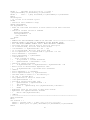
SystemDiag:
' This routine can test each device for operation and signal
' Test Routine uses the Chan() command, which is based on putting the
30
' 12 bit A/D conversion into the upper part of the 16 bit word.
PRINT: PRINT
' Turn on TPU Processor
TPUon()
' Turn on analog power
PSET 0
' Turn on Sensor Power
SDO PwrWord, 16
GOSUB ClearScreen
PRINT "
This Test Routine Prints out the actual Analog Voltages"
PRINT "
from all the Analog Inputs."
PRINT "
This should be helpful for system testing."
PRINT
PRINT
INPUT "
How Many Scans do you want? --> " Answer
Print
Hcount = 0
FOR I = 1 TO Answer
'Reset Mux
Pset 1
Sleep 0: Sleep 10
Pclr 1
IFF Hcount = 0
Print
Print "-Res/5- -ResX1- -ResX5- -*H2/5- -*H2X1- -*H2X5- -*Eh**- RefTemp
ResTemp -VBatt-"
ENDIF
' Get first 6 channels
FOR J = 0 to 6
Volts! = chan(J)*4.096/65520
print #5.3F, Volts;
print "
";
Next J
' Now get the Reference Temperature on the Mux
Volts = chan(7)*4.096/65520
print #5.3F, Volts;
print "
";
' Move the Mux to the Next Channel
Pset 1: Pclr 1
' Wait for it to Stabilize
Sleep 0 : Sleep 10
' Now get the Thermocouple Temperature on the Mux
Volts = chan(7)*4.096/65520
print #5.3F, Volts;
print "
";
' Move the Mux to the Next Channel
Pset 1: Pclr 1
' Wait for it to Stabilize
Sleep 0 : Sleep 10
' Now get the Battery Voltage
Volts = chan(7)*4.096/65520
' Multiply by 10
Volts = 10*Volts
print #5.3F, Volts;
print "
";
print
Hcount = Hcount + 1
IF Hcount = 20 Hcount = 0
Next I
31
INPUT "Press Enter to return to Main Menu." Answer
' Turn power off to sensors
SDO 0, 16
' Turn Power Off Too
Pclr 0
GOTO MainMenu
SetParameters:
GOSUB ClearScreen
PRINT "
System Parameter Menu"
PRINT
PRINT
"*****************************************************************************
"
PRINT
PRINT "
The present value for the Cycle Time is"
IFF MinOrSec = 0
PRINT "
",CycleTime," Seconds."
Endif
IFF MinOrSec = 1
PRINT "
",CycleTime," Minutes."
Endif
PRINT
PRINT "
The present setting for Verbose versus Data only is"
IFF Verbose = 0
PRINT "
Data Only."
Endif
IFF Verbose = 1
PRINT "
Verbose Printing of Status Information with the
Data."
ENDIF
PRINT
IFF VGET(9) = 0
PRINT "
Printing of the Metadata Printing on Power up is
inhibited."
ENDIF
IFF VGET(9) = 1
PRINT "
Printing of the Metadata Printing on Power up is
enabled."
ENDIF
PRINT
IFF VGET(10) = 0
PRINT "
Printing of the Metadata Printing on Restart of Data
is inhibited."
ENDIF
IFF VGET(10) = 1
PRINT "
Printing of the Metadata Printing on Restart of Data
is enabled."
ENDIF
PRINT
PRINT
"*****************************************************************************
"
PRINT: PRINT
PRINT "
Select one of the following functions:"
PRINT
PRINT "
0). Reprint this Menu."
PRINT "
1). Change the Cycle Time."
PRINT "
2). Change the Verbose Setting."
32
PRINT "
3). Change Print Status of Metadata on Powerup."
PRINT "
4). Change Print Status of Metadata on Restart
of Data."
PRINT "
5). Reset all Parameters back to Default
Settings."
PRINT "
6). Print out all Parameters."
PRINT "
7 to 9). Return to the Main Menu."
PRINT
INPUT "
Enter 0 through 9 here --> " A
IF A = 0 GOTO SetParameters
IF A = 1 GOSUB SetCycleTime
IF A = 2 GOSUB SetVerbose
IF A = 3 GOSUB SetMetadataStatus1
IF A = 4 GOSUB SetMetadataStatus2
IF A = 5 GOSUB ResetParameters
IFF A = 6
GOSUB ClearScreen
GOSUB PrintParameters
PRINT
INPUT " Press ENTER to continue. " A
ENDIF
IF A > 6 GOTO MainMenu
GOTO SetParameters
SetCycleTime:
GOSUB ClearScreen
Print "
Do you want to specify a Cycle Time in"
Print "
in Seconds or Minutes?"
Input "
Enter 0 for Seconds, 1 for Minutes --> " A
IF A < 0 | A > 1 GOSUB InputErrors: GOTO SetCycleTime
MinOrSec = A
Print
Print
IFF MinOrSec = 0
INPUT "
Enter a new value between 15 and 59 here --> " A
IF A < 15 | A > 59 GOSUB InputErrors: GOTO SetCycleTime
Endif
IFF MinOrSec = 1
INPUT "
Enter a new value between 1 and 60 here --> " A
IF A < 1 | A > 60 GOSUB InputErrors: GOTO SetCycleTime
Endif
CycleTime = A
' Save parameters to Eprom
VSTORE 1, CycleTime
VSTORE 2, MinOrSec
' Reset Variable A so no go back to Main Menu
A = 0
Return
SetVerbose:
GOSUB ClearScreen
Print " Do you want Verbose Status Information during Logging"
Print "
or just the Data?"
Input "
Enter 1 for Verbose, 0 for just Data. --> " Verbose
If Verbose < 0 GOTO SetVerbose
If Verbose > 1 GOTO SetVerbose
Return
SetMetadataStatus1:
33
GOSUB ClearScreen
Print " Do you want the Metadata Information printed out at Power up?"
PRINT
Input "
Enter 1 for Yes, 0 for No. --> " A
If A = 0 VSTORE 9, 0
If A = 1 VSTORE 9, 1
Return
SetMetadataStatus2:
GOSUB ClearScreen
Print " Do you want the Metadata Information printed out at restart of data
collection?"
PRINT
Input "
Enter 1 for Yes, 0 for No. --> " A
If A = 0 VSTORE 10, 0
If A = 1 VSTORE 10, 1
Return
SetPwrCntrl:
' Allow user to turn On/Off power to each sensor
GOSUB ClearScreen
IFF PwrWord < 0 | PwrWord > 55
PRINT "*************** WARNING !!! *******************"
PRINT
PRINT "
The Power Control Word = ", PwrWord
PRINT "
This is not possible!"
PRINT "
The Power Control Word must be a positive number < 56"
PRINT
PRINT "
This program is resetting this Word so that all sensors are
on."
PwrWord = 55
INPUT "
Press ENTER to Continue. " A
ENDIF
PRINT "
Sensor Power Control Menu"
PRINT
PRINT
"*****************************************************************************
"
PRINT
PRINT "
Here is the current status of power to each sensor"
PRINT
PRINT "
Res Sensor Power is ............. ";
IF ResPwrStatus = 1 PRINT "On"
IF ResPwrStatus = 0 PRINT "Off"
PRINT "
Instrumentation Amp Power is .... ";
IF InstrAmpPwrStatus = 1 PRINT "On"
IF InstrAmpPwrStatus = 0 PRINT "Off"
PRINT "
eH Isolation Amp Power is ....... ";
IF IsoPwrStatus = 1 PRINT "On"
IF IsoPwrStatus = 0 PRINT "Off"
PRINT "
Hydrogen Power .................. ";
IF H2PwrStatus = 1 PRINT "On"
IF H2PwrStatus = 0 PRINT "Off"
PRINT "
Reference Temperature Power ..... ";
IF RefTempPwrStatus = 1 PRINT "On"
IF RefTempPwrStatus = 0 PRINT "Off"
PRINT
34
PRINT
"*****************************************************************************
"
PRINT: PRINT
PRINT "
Select one of the following functions:"
PRINT
PRINT "
0). Reprint this Menu."
PRINT "
1). Toggle Power to Res Sensor."
PRINT "
2). Toggle Power to the Instrumentation Amp."
PRINT "
3). Toggle Power to the eH Isolation Amp."
PRINT "
4). Toggle Power to the Hydrogen Sensor."
PRINT "
5). Toggle Power to the Reference Temperature
Sensor."
PRINT "
6 to 9). Return to the Main Menu."
PRINT
INPUT "
Enter 0 through 9 here --> " A
IF A = 0 GOTO SetPwrCntrl
IF A = 1 GOSUB ToggleResPwr
IF A = 2 GOSUB ToggleInstrAmpPwr
IF A = 3 GOSUB ToggleIsoAmpPwr
IF A = 4 GOSUB ToggleH2Pwr
IF A = 5 GOSUB ToggleRefTempPwr
IF A > 5 GOTO MainMenu
GOTO SetPwrCntrl
ToggleResPwr:
'Check for errors first
IFF ResPwrStatus < 0 | ResPwrStatus > 1
GOSUB ClearScreen
PRINT " There has been a Error in the Power Control Word"
PRINT " Reset all Parameters back to Default Values using Main Menu
Option 2"
INPUT "Press ENTER to Continue. " A
GOTO SetPwrCntrl
ENDIF
' Toggle Res Power
IFF ResPwrStatus = 1
ResPwrStatus = 0
PwrWord = PwrWord - 1
VSTORE 3, PwrWord
VSTORE 4, ResPwrStatus
RETURN
ENDIF
IFF ResPwrStatus = 0
ResPwrStatus = 1
PwrWord = PwrWord + 1
ENDIF
VSTORE 3, PwrWord
VSTORE 4, ResPwrStatus
RETURN
ToggleInstrAmpPwr:
'Check for errors first
IFF InstrAmpPwrStatus < 0 | InstrAmpPwrStatus > 1
GOSUB ClearScreen
PRINT " There has been a Error in the Power Control Word"
PRINT " Reset all Parameters back to Default Values using Main Menu
Option 2"
INPUT "Press ENTER to Continue. " A
35
GOTO SetPwrCntrl
ENDIF
' Toggle Instrumentation Amp Power
IFF InstrAmpPwrStatus = 1
InstrAmpPwrStatus = 0
PwrWord = PwrWord - 2
VSTORE 3, PwrWord
VSTORE 5, InstrAmpPwrStatus
RETURN
ENDIF
IFF InstrAmpPwrStatus = 0
InstrAmpPwrStatus = 1
PwrWord = PwrWord + 2
ENDIF
VSTORE 3, PwrWord
VSTORE 5, InstrAmpPwrStatus
RETURN
ToggleIsoAmpPwr:
IFF IsoPwrStatus < 0 | IsoPwrStatus > 1
GOSUB ClearScreen
PRINT " There has been a Error in the Power Control Word"
PRINT " Reset all Parameters back to Default Values using Main Menu
Option 2"
INPUT "Press ENTER to Continue. " A
GOTO SetPwrCntrl
ENDIF
' Toggle eH Isolation Amp Power
IFF IsoPwrStatus = 1
IsoPwrStatus = 0
PwrWord = PwrWord - 4
VSTORE 3, PwrWord
VSTORE 6, IsoPwrStatus
RETURN
ENDIF
IFF IsoPwrStatus = 0
IsoPwrStatus = 1
PwrWord = PwrWord + 4
ENDIF
VSTORE 3, PwrWord
VSTORE 6, IsoPwrStatus
RETURN
ToggleH2Pwr:
IFF H2PwrStatus < 0 | H2PwrStatus > 1
GOSUB ClearScreen
PRINT " There has been a Error in the Power Control Word"
PRINT " Reset all Parameters back to Default Values using Main Menu
Option 2"
INPUT "Press ENTER to Continue. " A
GOTO SetPwrCntrl
ENDIF
' Toggle Hydrogen Sensor Power
IFF H2PwrStatus = 1
H2PwrStatus = 0
PwrWord = PwrWord - 16
VSTORE 3, PwrWord
VSTORE 7, H2PwrStatus
RETURN
36
ENDIF
IFF H2PwrStatus = 0
H2PwrStatus = 1
PwrWord = PwrWord + 16
ENDIF
VSTORE 3, PwrWord
VSTORE 7, H2PwrStatus
RETURN
ToggleRefTempPwr:
IFF RefTempPwrStatus < 0 | RefTempPwrStatus > 1
GOSUB ClearScreen
PRINT " There has been a Error in the Power Control Word"
PRINT " Reset all Parameters back to Default Values using Main Menu
Option 2"
INPUT "Press ENTER to Continue. " A
GOTO SetPwrCntrl
ENDIF
' Toggle Reference Temperature Sensor Power
IFF RefTempPwrStatus = 1
RefTempPwrStatus = 0
PwrWord = PwrWord - 32
VSTORE 3, PwrWord
VSTORE 8, RefTempPwrStatus
RETURN
ENDIF
IFF RefTempPwrStatus = 0
RefTempPwrStatus = 1
PwrWord = PwrWord + 32
ENDIF
VSTORE 3, PwrWord
VSTORE 8, RefTempPwrStatus
RETURN
ResetParameters:
VSTORE 0, 1
// Set EpromStatus = 1
VSTORE 1, 20
// Set CycleTime = 20 Minutes or Seconds depending on
MinOrSec
VSTORE 2, 0
// Set MinOrSec = 1 for Min, or = 0 for Sec
VSTORE 3, 55
// Set PwrWord = 55, Power Control Word for SDO
command = 1+2+4+16+32=55
VSTORE 4, 1
// Set ResPwrStatus = 1 for Power On
VSTORE 5, 1
VSTORE 6, 1
VSTORE 7, 1
VSTORE 8, 1
VSTORE 9, 0
// Set MetadataStatusPowerUp = 0 for no print on power up
VSTORE 10, 0
// Set MetadataStatusRestartData = 0 for no print on
restart
EpromStatus = VGET(0)
CycleTime = VGET(1)
MinOrSec = VGET(2)
PwrWord = VGET(3)
ResPwrStatus = VGET(4)
InstrAmpPwrStatus = VGET(5)
IsoPwrStatus = VGET(6)
H2PwrStatus = VGET(7)
RefTempPwrStatus = VGET(8)
MetadataStatusPowerUp = VGET(9)
37
MetadataStatusRestartData = VGET(10)
RETURN
PrintParameters:
' Eprom Storage location assignments (Only Locations 0-31 available)
'
0 .... Status, 0 means not setup yet, 1 means ready to use
'
1 .... CycleTime, Default = 20
'
2 .... MinOrSec, Default = 0
'
3 .... PwrWord, Default = 55
'
4 .... ResPwrStatus, Default = 1
'
5 .... InstrAmpPwrStatus, Default = 1
'
6 .... IsoPwrStatus, Default = 1
'
7 .... H2PwrStatus, Default = 1
'
8 .... RefTempPwrStatus, Default = 1
'
9 .... MetadataStatusPowerUp, Default = 0
'
10 .... MetdataStatusRestartData, Default = 0
PRINT " This System is presently setup with the following Parameters:"
PRINT VGET(0), " = Eprom Status (0 means not setup yet, 1 means ready to
use)"
PRINT VGET(1), " = Cycle Time (Actual Time in Seconds or Minutes)"
PRINT VGET(2), " = Minutes or Seconds Cycle Time (0 = Seconds mode, 1 =
Minutes mode)"
PRINT VGET(3), " = Power Control Word (Power Control Word = 1+2+4+16+32 = 55
if all On)"
PRINT VGET(4), " = Res Power Status (0 = Off, 1 = On)"
PRINT VGET(5), " = Thermocouple & Hydrogen Amp Power Status (0 = Off, 1 =
On)"
PRINT VGET(6), " = eh Amp Power Status (0 = Off, 1 = On)"
PRINT VGET(7), " = Hydrogen Sensor Power Status (0 = Off, 1 = On)"
PRINT VGET(8), " = Reference Temperature Power Status (0 = Off, 1 = On)"
PRINT VGET(9), " = Metadata Print Status on Power up (0 = No Print on
Powerup, 1 = Print)"
PRINT VGET(10), " = Metadata Print Status on Restart Data Collection (0 = No
Print on Restart Data, 1 = Print)"
RETURN
SysInfo:
' Print out System Information to identify this system
GOSUB ClearScreen
GOSUB PrtSysInfo
PRINT
GOSUB PrintParameters
PRINT
INPUT " Press Enter to return to the Main Menu. --> " A
GOTO MainMenu
PrtSysInfo:
PRINT
PRINT " System Name: BARS (Benthic And Resistivity Sensors)"
PRINT " System Owner: Marv Lilley, University of Washington"
PRINT " Owner Contact Phone #: 206-543-0859"
PRINT " System Serial #: 001"
PRINT " Software Version 1.86, Last Update March 28, 2012"
PRINT " Made by Ocean Engineering Services, July 2010 (206-543-9688)"
RETURN
AreYouSure:
' To verify that user really wants to stop this program
GOSUB ClearScreen
38
PRINT " You have requested to stop this program."
PRINT
PRINT " Once the Program has been stopped, to restart the program,"
PRINT " just cycle the system power. This system is programmed as"
PRINT " Plug and Play, so it will power up running."
PRINT
PRINT " Are you really sure that you want to stop this program?"
INPUT "
Enter 1 for Yes, 0 for No --> " A
IFF A = 1
' Stop the program
' Turn Off Everything
GOSUB TurnOffEverything
STOP
ENDIF
GOTO MainMenu
SetupToTakeData:
'Check to see if print Metadata
IFF VGET(10) = 1
GOSUB PrtSysInfo
PRINT
GOSUB PrintParameters
PRINT
ENDIF
TakeData:
HeaderStatus = 0
' Setup the Starting Time & Date Array
' Alway set start time to actual time
RTIME
BrtTimeSec = ?(0)
BrtTimeMin = ?(1)
BrtTimeHr = ?(2)
BrtTimeDay = ?(3)
BrtTimeMon = ?(4)
BrtTimeYr = ?(5)
' If in Minute mode, Seconds always = 0
If MinOrSec = 1 BrtTimeSec = 0
If MinOrSec = 0 BrtTimeSec = ?(0)
' Print "Calculated BrtTimeSec = ", BrtTimeSec
Goto SetupToLog
' No need this section
' Check for overflow
IFF BrtTimeSec > 59
BrtTimeSec = 0
BrtTimeMin = BrtTimeMin + 1
Endif
Iff BrtTimeMin > 59
BrtTimeMin = 0
BrtTimeHr = BrtTimeHr + 1
EndIF
Iff BrtTimeHr > 23
BrtTimeHr = 0
BrtTimeDay = BrtTimeDay + 1
EndIF
IF BrtTimeDay > 28 & BrtTimeMon = 2 GOTO AnotherDay
IF BrtTimeDay > 30 & BrtTimeMon = 4 GOTO AnotherDay
IF BrtTimeDay > 30 & BrtTimeMon = 6 GOTO AnotherDay
39
IF BrtTimeDay > 30 & BrtTimeMon = 9 GOTO AnotherDay
IF BrtTimeDay > 30 & BrtTimeMon = 11 GOTO AnotherDay
IF BrtTimeDay < 32 GOTO SetupToLog
AnotherDay:
BrtTimeDay = 1
BrtTimeMon = BrtTimeMon + 1
IF BrtTimeMon < 12 GOTO SetupToLog
BrtTimeMon = 1
BrtTimeYr = BrtTimeYr + 1
GOTO SetupToLog
CalNextBurstTime:
RTIME
' Calculate the next Burst Date & Time
' Add CycleTime to get to next burst
' CycleTime can be Seconds or Minutes depending on Value of MinOrSec
IFF MinOrSec = 0
BrtTimeSec = BrtTimeSec + CycleTime
BurstTimeLoop0:
' Check to see if overflow
IF BrtTimeSec < 60 GOTO LogLoop
BrtTimeSec = BrtTimeSec - 60
BrtTimeMin = BrtTimeMin + 1
if BrtTimeSec > 59 goto BurstTimeLoop0
Endif
IFF MinOrSec = 1
BrtTimeMin = BrtTimeMin + CycleTime
Endif
BurstTimeLoop1:
' Check to see if overflow
IF BrtTimeMin < 60 GOTO LogLoop
BrtTimeMin = BrtTimeMin - 60
BrtTimeHr = BrtTimeHr + 1
if BrtTimeMin > 59 goto BurstTimeLoop1
CheckHours:
IF BrtTimeHr < 24 GOTO LogLoop
BrtTimeHr = BrtTimeHr - 24
BrtTimeDay = BrtTimeDay + 1
IF BrtTimeDay > 28 & BrtTimeMon = 2 GOTO NextDay
IF BrtTimeDay > 30 & BrtTimeMon = 4 GOTO NextDay
IF BrtTimeDay > 30 & BrtTimeMon = 6 GOTO NextDay
IF BrtTimeDay > 30 & BrtTimeMon = 9 GOTO NextDay
IF BrtTimeDay > 30 & BrtTimeMon = 11 GOTO NextDay
IF BrtTimeDay < 32 GOTO LogLoop
NextDay:
BrtTimeDay = 1
BrtTimeMon = BrtTimeMon + 1
IF BrtTimeMon < 12 GOTO LogLoop
BrtTimeMon = 1
BrtTimeYr = BrtTimeYr + 1
LogLoop:
RTIME
IFF Verbose = 1
PRINT
PRINT "
The Present Date & Time is -> Date = ",#02,?(4),"/",?(3),"/",?(5);
PRINT "
Time = ",#02, ?(2),":",?(1),":",?(0)
' Print next cycle date / time
40
PRINT "
The Next Cycle will be at --> Date =
",#02,BrtTimeMon,"/",BrtTimeDay,"/",BrtTimeYr;
PRINT "
Time = ",#02, BrtTimeHr,":",BrtTimeMin,":",BrtTimeSec
Endif
AnotherCycle:
' Is it time to do another cycle?
RTIME
' Check for User command to Stop
GOSUB UserCommand
IFF KeyCommand = 19
' Send out Line Feed and Return to show Control-S has been received
PRINT
' Check for another Control-S Command
GOSUB UserCommand
IFF KeyCommand = 19
Goto MainMenu
Endif
Endif
' REMOVE ALL THE FOLLOWING LINES UP TO THE LINE *************************
' BECAUSE THERE IS NO NEED TO HYBERNATE ON THE NEPTUNE CABLE
' ALL LINE WITH COMMENT SYMBOL PLUS * WERE ORGINALLY COMMANDS
' Calculate how much time we have to wait for next Cycle
' If in Minute Mode, wait for next whole minute
' *IF MinOrSec = 1 HybernateTime = 60 - ?(0)
' If in Second Mode, Wait for next Cycle time
' Do not Hybernate if in Second mode & CycleTime < 15 sec
' Print "MinOrSec = ",MinOrSec
' Print "BrtTimeSec = ",BrtTimeSec
' *IFF MinOrSec = 0
'
Print "Inside If Loop"
' *
IF CycleTime < 15 GOTO CheckTime
' *
HybernateTime = BrtTimeSec - ?(0)
' Check for change of Minute
' *
If HybernateTime < 0 HybernateTime = HybernateTime + 60
' Never allow an unreasonable Hybernate Time
' *
If HybernateTime > CycleTime Goto CheckTime
' *Endif
' Print "MinOrSec = ", MinOrSec
' Print "HybernateTime = ", HybernateTime
' The Next make no sense so I am removing it
' IF ?(0) >= 59 GOTO Wait
' Only Hybernate if there is extra time
' *IFF HybernateTime > 8
' Provide 4 second count down time
' *
HybernateTime = HybernateTime - 4
' *
IFF Verbose = 1
' *
Print "
Hybernating for ",HybernateTime," Seconds."
' *
Endif
' Hybernate until we are close to next whole minute
' Hybernate for (HybernateTime) seconds
' *
HYB 0: HYB (HybernateTime)
' *ENDIF
' *************************************************************************
GOTO CheckTime
Wait:
IFF Verbose = 1
PRINT " Current Time = ",#02, ?(2),":",?(1),":",?(0);
PRINT " Next Cycle at ",#02, BrtTimeHr,":",BrtTimeMin,":",BrtTimeSec
Endif
41
WaitLoop:
' Print "In WaitLoop, BrtTimeSec = ", BrtTimeSec, " Actual Seconds = ", ?(0)
RTIME
IFF MinOrSec = 1
IF ?(0) <> 0 GOTO WaitLoop
Endif
IFF MinOrSec = 0
IF ?(0) <> BrtTimeSec GOTO WaitLoop
GOTO SetupToLog
Endif
CheckTime:
' Print "Checking Time"
' Print BrtTimeHr," ",?(2)," ", BrtTimeMin," ", ?(1)," ", BrtTimeSec," ", ?(0)
IF BrtTimeHr = ?(2) & BrtTimeMin = ?(1) & BrtTimeSec = ?(0) GOTO SetupToLog
' Check if we have missed the right time
IF BrtTimeHr = ?(2) & BrtTimeMin = ?(1) & ?(0) > BrtTimeSec GOTO SetupToLog
IF BrtTimeHr = ?(2) & BrtTimeMin < ?(1) GOTO SetupToLog
GOTO AnotherCycle
UserCommand:
' Check for User Command to Stop Logging (Control-S = 19)
' Be sure KeyCommand word = 0
KeyCommand = 0
' Save Memory Pointer
SavePointer = Pointer
' Save Contents of Memory
SaveData = Get(Pointer,#2)
' Decrement Pointer
Pointer = Pointer - 2
' Be sure Memory is Zero
MemValue = 0
Store Pointer, #1, MemValue
' Backup one memory location
Pointer = Pointer - 1
' Look for Keyboard Entry
Iff Verbose = 1
Print "
Enter Control-S ** NOW ** to Stop.
"
Endif
' Print Current Time
RTIME
Iff Verbose = 1
PRINT " Current Time = ",#02, ?(2),":",?(1),":",?(0);
Endif
' Print next cycle time if not in Shipping Mode or Low Battery Mode
If LowBattMode = 1 Print "
Vbatt = ", Vbatt!
IFF LowBattMode = 0 & Verbose = 1
PRINT " Next Cycle at ",#02, BrtTimeHr,":",BrtTimeMin,":",BrtTimeSec
Endif
' Otherwise Print Date too
IFF Verbose = 1
If LowBattMode = 1 PRINT "
Date = ",#02,?(4),"/",?(3),"/",?(5)
Endif
ITEXT Pointer, 80
' If character stored, adjust memory size
IFF Pointer <> SavePointer
Pointer = SavePointer
' Get the Keyboard entry
KeyCommand = GET(Pointer, #1)
' Restore Pointer
42
Pointer = SavePointer
ENDIF
' Restore Original Memory
Store Pointer, #2, SaveData
' Decrement Pointer
Pointer = Pointer - 2
return
SetupToLog:
' Check for User command to Stop
GOSUB UserCommand
IFF KeyCommand = 19
Goto MainMenu
Endif
IFF Verbose = 1
Print
Print "Starting to log a burst of Data to memory."
Endif
' Turn on TPU Processor
TPUon()
' Turn on Analog Power
PSET 0
' Turn on Sensor Power
SDO PwrWord, 16
' Wait a little for power to stabilize
SLEEP 0: SLEEP 400
' Reset Mux
PSET 1
Sleep 0: Sleep 10
Pclr 1
' Move Mux to Battery Channel (Mux2)
For I = 1 to 2
Pset 1: Pclr 1
' Wait for Mux to stabilize
Sleep 0: Sleep 10
Next I
CheckBattery:
' Check the Battery Voltage
' Take 10 values and average
Vave! = 0
BatSum = 0
For I = 1 to 10
Raw = Chan(7)
BatSum = BatSum + Raw
Vbatt! = (40.96*Raw/65536)
Vave = Vbatt + Vave
next I
Vbatt = Vave/10
IFF Verbose = 1
print
print "The Battery voltage is ";
print #5.3F, Vbatt;
print " Volts."
Endif
StartBurst:
IFF Verbose = 1
Print
'************************************************
43
' Print Header
IFF HeaderStatus = 0
Print "Res/5 ResX1 ResX5 *H2/5 *H2X1 *H2X5 *eH** Ref-T
Res-T Vbatt"
Print "Volts Volts Volts Volts Volts Volts Volts Volts
Deg-C Volts"
HeaderStatus = 1
Endif
Endif
'Reset Mux
Pset 1
Sleep 0: Sleep 10
Pclr 1
' Read the starting time
RTIME
' Get Res, Hydrogen, Ref Temp Data and Average (10 values)
Res1Ave = 0
Res2Ave = 0
Res3Ave = 0
H1Ave = 0
H2Ave = 0
H3Ave = 0
EhAve = 0
RefTempAve = 0
Sleep 0
For I = 1 to 10
Res1Ave = Res1Ave + Chan(0)/16
Res2Ave = Res2Ave + Chan(1)/16
Res3Ave = Res3Ave + Chan(2)/16
H1Ave = H1Ave + Chan(3)/16
H2Ave = H2Ave + Chan(4)/16
H3Ave = H3Ave + Chan(5)/16
EhAve = EhAve + Chan(6)/16
RefTempAve = RefTempAve + Chan(7)/16
Next I
Res1Ave = Res1Ave/10
Res2Ave = Res2Ave/10
Res3Ave = Res3Ave/10
H1Ave = H1Ave/10
H2Ave = H2Ave/10
H3Ave = H3Ave/10
EhAve = EhAve/10
RefTempAve = RefTempAve/10
' ***********************************************
' Note all A/D data is divided by 16
' Since it is only 12 but data shifted into 16 bits
' This helps to identify the BOF Markers later!
' ***********************************************
Volts! = Float(Res1Ave)/1000
Print #5.3F,Volts;
Print " ";
Volts = Float(Res2Ave)/1000
Print #5.3F,Volts;
Print " ";
Volts = Float(Res3Ave)/1000
Print #5.3F,Volts;
Print " ";
Volts! = Float(H1Ave)/1000
Print #5.3F,Volts;
44
Ref-T
Res-T
Deg-C
Volts
Print " ";
Volts = Float(H2Ave)/1000
Print #5.3F,Volts;
Print " ";
Volts = Float(H3Ave)/1000
Print #5.3F,Volts;
Print " ";
Volts = Float(EhAve)/1000
Print #5.3F,Volts;
Print " ";
Volts = Float(RefTempAve)/1000
Print #5.3F,Volts;
Print " ";
' Convert Reference Thermistor Value
ThermistorMVolts = RefTempAve
ThermistorVolts! = Float(ThermistorMVolts)/1000
Gosub ConvertThermistorTemp
Print " ";
' Save Thermistor Temp too
' Need to convert it to mC * 10
' so it is same format as Thermocouple
Tmp = INT(P!*100.)
' Get Thermocouple Temp
' Move Mux to Next Channel
Pset 1: Pclr 1
' Wait for it to stabilize
Sleep 0: Sleep 10
' Take 10 values of Res Temp and average
ResAveTemp = 0
For I = 1 to 10
ResAveTemp = ResAveTemp + Chan(7)/16
Next I
ResAveTemp = ResAveTemp/10
Volts = Float(ResAveTemp)/1000
Print #5.3F,Volts;
Print " ";
ThermoMVolts = ResAveTemp
ThermoVolts! = Float(ThermoMVolts)/1000
Gosub ConvertThermoTemp
Print " ";
' Save Thermocouple Temp too
' Need to convert it to mC * 10
' so it is not too big to store
Tmp = INT(T!*100.)
' Already Have Battery Voltage so just print it
Print #4.1F, Vbatt;
Print
' Turn power off to sensors
SDO 0, 16
' Turn off Analog Power
Pclr 0
DoneLogging:
Iff Verbose = 1
Print
Print "
Print
Endif
Memory Pointer = ",Pointer
45
ThisCycleIsDone:
'************************************************
TPUoff()
' Update PrevHour Variable
PrevHour = ?(2)
Goto CalNextBurstTime
' Subroutine to convert A/D value ThermistorVolts & print Temp in Degrees C
' Thermistor voltage (Volts) = Y
' Thermistor Temp (C) = P = 27.50133 - (17.2658*Y) + 15.83424/Y
ConvertThermistorTemp:
Y! = ThermistorVolts
' Do not allow Thermistor voltage to be zero or very small
IF Y < 0.5 Y = 0.5
P! = 27.50133 - (17.2658*Y) + 15.83424/Y
Print #4.2F, P;
RETURN
' Subroutine to convert A/D value ThermoMVolts & print Sensor Temp in Degrees
C
' Thermocouple Voltage (Volts) = E = ThermoVolts
' Thermocouple Temp (C) = K = (244970*E)/1000
' Corrected Sensor Temp (C) = T = Th + P
ConvertThermoTemp:
E! = (ThermoVolts)
Th! = (244970*E)/1000
T! = Th + P
Print #5.1F, T;
RETURN
ErrorRoutine:
' Go here in case of a problem with the Software, so can try to recover
' Turn everything off
Gosub TurnOffEverything
Print
Print
Print "
************************* WARNING !!!
****************************"
Print
Print "
There has been a problem with the Software!"
Print "
and this program is attempting to recover."
Print
print "
Turning all sensor power off."
print
GOTO CalNextBurstTime
TurnOffEverything:
' Note the following are reverse logic
PSET 6, 9, 10, 11, 12, 15
' Turn off all sensor power
SDO 0, 16
' Turn off analog power
Pclr 0
ADoff()
TPUoff()
RETURN
CharCount = 0
DecodeLoop:
46
Char = Get(DecodeMem,#1)
Print "The character = ", Char
Input "Waiting " A
If Char = 13 goto Convert
' If the character is not a real number (48 to 57), ignore it
If Char < 48 goto DecodeLoop
If Char > 57 goto DecodeLoop
CharCount = CharCount + 1
D(CharCount) = Char - 48
Goto DecodeLoop
Convert:
' Convert the Data
' For I = 1 to CharCount
'
Print "D(",I,") = ", D(I)
' Next I
NumBlocks = 0
IFF CharCount = 1
NumBlocks = D(1)
Return
Endif
For I = 1 to (CharCount)
GOSUB PowerofTen
NumBlocks = PwrTen * D(I) + NumBlocks
Next I
Return
'
'
PowerofTen:
' Routine to get powers of 10
PwrTen = 1
For J = 1 to (CharCount-I)
PwrTen = 10 * PwrTen
Next J
Return
InputErrors:
' Input Error Routine
PRINT ""
PRINT "
The value you have entered is not within valid limits!"
PRINT "
Please Try Again!"
PRINT " "
PRINT "
Press ENTER to Continue."
INPUT ""A
RETURN
ClearScreen:
' Clear the screen
FOR I = 1 TO 50
PRINT
NEXT I
RETURN
Finish:
' **This routine is not used on the Canadian Version
' Stop the program
' Turn Off Everything
GOSUB TurnOffEverything
STOP
47
48
Section 3
System Schematics
49
50
51
52
53
54
BARS Motherboard – Component Side
55
BARS Motherboard – Back side
56
57
58
59
60
61
62
63
64
65
66
67
68
69
Section 4
System Mechanical Drawings
70
71
72
73
74
75
76
77
78
79
80
81
82
83
84
85
86
87
88
89
90
91
92
Section 5
System Notes
93
94