1
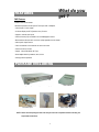
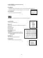
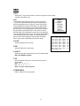
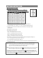
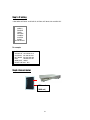
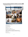
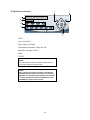
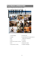
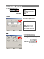
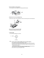
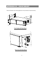
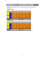
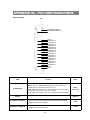
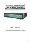
9 CH Digital Multiplex Recorder
User Manual
USER’S MANUAL
Please read this instructions thoroughly before operation and retain it for future reference.
776 W V 1.0
WARNING
All the safety and operating instructions should be read before operation. The improper operation may cause
permanent damage.
• Please use the provided adaptor (Other adaptor is not suitable for this machine).
• Please lift and place this equipment gently.
• Do not expose this equipment to open sunlight.
• Do not use this equipment near water or in contact with water.
• Do not spill liquid of any kind on the equipment.
• Please power down the unit before unplugging.
• Do not switch the Power On & Off within short period of time (within 3 seconds).
• Do not attempt to have this equipment serviced by yourself.
• Installation should be made by qualified service personnel.
The lightning flash with arrowhead symbol, within an equilateral triangle, is intended to alert
the user to the presence of uninsulated "dangerous voltage" within the product's enclosure that
may be of sufficient magnitude to constitute a risk of electric shock to persons.
The exclamation point within an equilateral triangle is intended to alert the user to the presence
of important operating and maintenance-(servicing) instructions in the literature accompanying
the appliance.
TABLE OF CONTENTS
What do you get ?
• FEATURES ---------------------------------------------------------------------------------------- 1
• PACKAGE INCLUDING ------------------------------------------------------------------------ 1
Before Operation
• INSTALLATION GUIDE ------------------------------------------------------------------------ 2
• FRONT PANEL -----------------------------------------------------------------------------------
3
• BACK PANEL ------------------------------------------------------------------------------------- 5
Basic Operation
• START THIS UNIT -------------------------------------------------------------------------------- 6
• OPERATION ---------------------------------------------------------------------------------------- 6
Detailed Menu Setup
• ACCESS MENU ----------------------------------------------------------------------------------
8
• MAIN MENU ---------------------------------------------------------------------------------------
8
• MENU OPTIONS ---------------------------------------------------------------------------------
9
• MOTION DETECTION --------------------------------------------------------------------------
13
Network Setting Guide
•
HARDWARE CONNECTION AT DMR SIDE -------------------------------------
16
•
STATIC IP SETTING -------------------------------------------------------------------
17
•
DYNAMIC IP SETTING -----------------------------------------------------------------
21
•
SOFTWARE OPERATION AT CLIENT SIDE -------------------------------------
33
•
INTRODUCTION OF BASIC OPERATION-----------------------------------------
34
•
PLAYBACK OPERATION--------------------------------------------------------------
36
•
ADVANCED SETTING-------------------------------------------------------------------
37
•
CONNECT VIDEO WEB SERVER VIA IE BROWSER--------------------------
40
TABLE OF CONTENTS
Advanced Operation
• OPERATION OPTIONS -------------------------------------------------------------------- 42
• KEY LOCK ------------------------------------------------------------------------------------ 43
• TROUBLE SHOOTING --------------------------------------------------------------------- 43
• SPECIFICATIONS --------------------------------------------------------------------------- 44
APPENDIX #1 – INSTALLING THE HDD -----------------------------------------------------
45
APPENDIX #2 –RACK MOUNT - -----------------------------------------------------------------
47
APPENDIX #3 – RECORDING SPEED --------------------------------------------------------
48
APPENDIX #4 – PIN CONFIGURATIONS ----------------------------------------------------
49
What do you
get ?
FEATURES
DMR Features
•Remote control via the internet
•Wavelet Compression Format replaces Time-Lapse VCR + Multiplexer
• 4 Audio inputs / 2 Audio outputs
• On Screen Display and RTC (Real time clock) Function
• Support 9 channels video inputs
• Picture-In-Picture (PIP) is available in live and DMR playback modes
• Motion detection function and 4 Level video quality adjustable on each channel
• Alarm Input & Output Function
• Video loss detected on each channel can record 160 events
• Power-loss memory function
• Support 1 Removable HDDs, IDE Type
• Quick Multiple Search by date/time, alarm, full list
• Security password protection
PACKAGE INCLUDING
Digital Multiplex Recorder(with HDD cartridge)
Accessories pack
User’s Manual
Power Adapter and Cord
2 Keys
NOTE : Please check the package to make sure that you receive the complete accessories including the
components shown above.
1
Before Operation
INSTALLATION GUIDE
1. Connect cameras and monitor with the DMR.
2. Shown below is one example for connecting the DMR to your existing Observation System.
3. Install HDDs (The compatible HDD Brands are listed in the following table.)
Please refer to page.45 Appendix #1 for installation instructions.
The HDDs must be installed before turning on the DMR.
Main Monitor
Alarm
Sensor
MAIN
LOOP
RISK OF EL ECT RIC SHOCK
DO NOT OPEN
Audio
IN
OU T
WARNING: TO REDUCE THE RISK OF ELECT RIC SHOCK,
DO NOT REM OVE COVER (OR BACK).
NO USER- SERVICEABLE PART S INSIDE.
REFERSERVICI NG T OQUALIFIED
SERVICE PERSONNEL.
HI
LAN
INPUT
1
3
R
2
4
L
ACT
LINK
POWER
EXTERNAL I/O
75Ω
CALL
Power
Camera 1
Camera 9
Call Monitor
Speaker
COMPATIBLE HARD DISK BRANDS
Manufacturer
HITACHI
HITACHI
HITACHI
IBM
IBM
Maxtor
Maxtor
Maxtor
Maxtor
Maxtor
Seagate
Seagate
Seagate
Western Digital
Western Digital
Western Digital
Model
Deskstar 180 GXP (120 GB)
Deskstar 7K250, HDS722516VLAT20
Deskstar 7K250, HDS722525VLAT80
Deskstar 120GXP (80GB)
Deskstar 120GXP (120GB)
DiamondMax 536DX(60GB) 4W060H4
DiamondMax Plus 9
DiamondMax Plus 9, Model#6Y120L
DiamondMax Plus 9, Model#6Y160L0
MaxLine Plus Ⅱ, Model#7Y250P0
Barracuda ATA IV, ST380021A
Barracuda ATA V, ST3120023A
Barracuda 7200.7 Plus, ST3160023A
Caviar WD1200BB-00CAA1
Caviar WD2000BB-00DWA0
CaviarSE WD2500JB
2
Capacity
120GB
160GB
250GB
80GB
120GB
60GB
80GB
120GB
160GB
250GB
80GB
120GB
160GB
120GB
200GB
250GB
Rotation
7200 rpm
7200rpm
7200rpm
7200 rpm
7200 rpm
5400rpm
7200 rpm
7200 rpm
7200rpm
7200rpm
7200rpm
7200 rpm
7200 rpm
7200rpm
7200rpm
7200rpm
FRONT PANEL
17 16 15 14 13
18
SLOW
AVC 776
Up
Digital Multiplex Recorder
1
2
3
4
5
6
7
8
9
Right
Left
REC
MENU
1
2
ENTER
3 4
SELECT
ZOOM
5
6
Down
7 8
9
10
1. REMOVABLE HDD CARTRIDGE
Please refer to page.45 Appendix #1.
2. LED LIGHT
The LED Light is ON under following condition.
•HDD : HDD is activated
•HDD Full : HDD is full
•ALARM : If you want to turn off the ALARM LED light, please refer to page.12 and set the
Camera / ALARM item as OFF. (all of the cameras should be set as OFF.)
•TIMER : When Timer is set as Enabled
•PLAY : On Play mode
•REC : On Recording mode
3. MENU
Press MENU to enter main menu.
4. ENTER
Press ENTER for confirmation.
5. SELECT
Press the Select to select appointed camera (1~9) to display on full screen mode.
6. ZOOM
Press ZOOM to enlarge the picture display.
7.
Press PIP button for Picture in Picture screen.
8.
4 and 7 channels display mode
9.
9 channels display mode
3
11
POWER
12
10. REC
Press REC to start recording.
11. STOP / DOWN
•STOP : Under DMR Record / Play mode, it can stop the moment action.
•DOWN : Under setup mode, it works as Down button.
12. POWER
Press Power to turn ON / OFF the DMR.
13. FF / Right
•FF : It can play video forward at high speed.
(Press FF again to adjust speed from 1, 2, 4, 8, 16, 32 times)
•Right : Under setup mode, it can work as Right button.
14. PAUSE / UP
•Pause : Under DMR play mode, it can pause the action.
•UP : Under setup mode, it works as Up button.
15. PLAY
Press PLAY to play recorded video.
16. REW / LEFT
•REW : Under DMR play mode, it can play video backward at different speeds.
(Press REW again to adjust speed as 1, 2, 4, 8, 16, 32 times)
•Left : Under setup mode, it works as Left button.
17. SLOW
To slow down speed of play mode.
18. CAMERA (1-9)
Press the Camera Select (1-9) to select specified camera.
4
BACK PANEL
⑨
⑥
MAIN
LOOP
R ISK OF ELE CTR IC SHOC K
D O N OT OPEN
⑦
⑧
IN
OUT
WARNING : TO R ED UCE THE R ISK OF ELEC TRIC SHOCK,
D O NOT REMOVE C OVER (OR BACK).
NO USER-SERVIC EABLE PARTS IN SIDE.
REFER SERVICING TO QUALIFIED
SERVICE PERSONNEL.
HI
LAN
INPUT
1
3
R
2
4
L
ACT
LINK
POWER
75Ω
EXTERNAL I/O
①
②
③
CALL
⑤
④
⑩
1. POWER
Please use the provided adaptor to connect power cord (Other adaptor is not suitable for this machine).
2. EXTERNAL I/O
•Controlled remotely by an external device or control system.
•Alarm input, external I / O explanation.
3. 75Ω / HI
When using Loop function, please switch to HI. If you don’t use Loop function or disconnect the video
input, please set it as 75Ω.
4. VIDEO INPUT (1-9)
Connect to video source, such as camera.
5. CALL
Connect to CALL monitor. Show the Switch Display. When alarm trigger happens, the call monitor will show
the triggered channel for a period of time.
6. AUDIO OUT (R/L)
Connect to monitor or speaker.
•IPS should be set to 25A (for NTSC) or 18A (for PAL)
✻ with 2 mono audio outputs from the same source.
7. AUDIO IN (1-4)
Connect to audio source, such as microphone.
•IPS should be set to 25A (for NTSC) or 18A (for PAL)
✻ 4 audio inputs, but only can select 1 during recording.
8. MAIN
Connect to Main monitor
9. LOOP (1-9)
Connect video signal between Input port and Loop port to make a loop.
10. LAN
Connect DMR by network.
5
Basic Operation
START THIS UNIT
Before using the DMR, please have the HDDs installed ready. (refer to Appendix #1 for installation or removal of HDDs).
1. Connect the AC Power Cord with Power Adapter and plug into an electrical outlet. The Red LED indicator light will be
ON and the DMR is in Standby mode.
2. Press the Power button. The POWER LED will turn from red to orange, and other red LED indicators will be turn ON. It
takes approximately 5 to 15 seconds to boot the system with the message : “ HDD Detecting ”. Once being connected,
the POWER LED will change to green color, and the Alarm LED will be ON.
3. Before operating the DMR, please set up the system time first. (for setting system time, please refer to page.11).
NOTE : When “HDD not found” message shows up, please refer to appendix # 1. Because the HDD is probably
not installed correctly.
OPERATION
RECORDING
The DMR offers a variety of recording modes, such as record continuously, at scheduled time, and by events. You can set
up recording speed and resolution. You can set these options by selecting MENU / RECORD before recording, please refer
to page.12. Under the recording status, if power is off accidentally, recorded video will still be saved in the HDDs. DMR will
return to original recording situation after power returns again.
On the screen, you will find the date, time, HDD recording type and the letter “M” represents the method of recording that is
occurring.(OW : HDD Overwrite)
2002 – JAN –01 01:02:03
M● OW
NOTE : 1. When the HDDs are full under O/W Recording mode, previous recorded
files may be overwritten without further warning notices.
2. If the HDDs’ capacity only has 5 GB left, it will buzz for 3 seconds; so as in 4GB, 3GB, 2GB and
1GB. If the O/W Recording mode(NOTE 1) is on, it won’t have the warning buzzer.
There are 4 recording modes in which Recording can occur : Alarm, Timer, Manual and Motion Trigger Record.
1. ALARM RECORD
DMR is triggered by an alarm input. Indicated by the letter “A” and show
diagram on the triggered channel.
2. TIMER RECORD
Recording is scheduled by a Timer. Indicated by the letter “T”.
3. MANUAL RECORD
Recording is initiated by manually pressing the REC button. Indicated by the letter “M”.
4. MOTION TRIGGER RECORD
Recording is triggered by motion detection. Indicated by the letter “D” and show
6
diagram on the triggered channel.
PLAY
Press “ PLAY ” button, the DMR will show the last recording.
1. FAST FORWARD (F.F. ) & FAST REWIND (F.R.)
You can increase the speeds of Fast Forward and Rewind on the DMR.
In the Play mode, press ” ►► ” once to get 1X speed forward and press twice to get 2X speed,… and the maximum
speed can reach 32X.
Press ”◄◄ ” once to get 1X speed rewind and press twice to get 2X speed, … and the maximum speed can reach
32X.
2. SLOW FORWARD (S.F.) & SLOW REWIND (S.R.)
You can also slow down the speeds of Forward and Rewind on the DMR.
In the Play mode, press the SLOW button and you will enter Slow mode.
Press ” ►► ” once to get 1/2X speed forward and press twice to get 1/4X speed,… and the slowest speed can reach
1/32X.
Press ”◄◄ ” once to get 1/2X speed rewind and press twice to get 1/4X speed, … and the slowest speed can reach
1/32X.
3. PAUSE
It will let you pause the current image displayed on the screen.
4. STOP
Press “ STOP ” under any circumstance, it will return DMR to live monitoring mode.
5. IMAGE JOG DIAL
It will allow you to manually view video frame-by-frame, one image at a time.
While in PLAY mode, press “ PAUSE ”, it will pause the screen.
Press “ ►► ” button to advance the frozen screen one image forward.
Press “ ◄◄ ” button to move back one image.
CAMERA SELECT (1--9)
Press Camera Select (1-9) to select appointed camera to display on full screen mode.
7
Detailed Menu
Setup
ACCESS MENU
The Menu allows you to configure your DMR settings. Please follow the
steps below to access the Menu :
Press the Menu button. The password screen will appear:
Password: 0000
NOTE : The default Password is 0000. Simply press the Enter button to access the Menu.
To key-in the Password, press the “Right” and “Left” buttons to move between numbers, and use the “Up”
and “Down” buttons to key in the number.
Press the ENTER button once the correct Password is entered. The MENU options screen will appear.
Note: If you get a message “Password Error”, you have entered an incorrect password.
MAIN MENU
There are 6 options available in the Main Menu:
(MENU)
► SEARCH
TIMER
RECORD
CAMERA
SYSTEM
EVENT
NETWORK
SEARCH -------- Find recorded list
TIMER ---------- Scheduling Record
RECORD ------- Record Mode Setup
CAMERA ------- Camera Channel Setup
SYSTEM -------- System Setup
EVENT ---------- Event List
NETWROK------ Network Setup
Outlined below are the buttons used for Menu setting :
•“Up” and “Down” : Scroll up and down or change values when an option is selected and is blinking
•“Left” and “Right” : Scroll sideways within a menu option that has been selected
•ENTER : Selects a submenu / an option under a submenu for browsing / modification
•MENU : Completes modification of a menu option; exits a menu
8
MENU OPTIONS
SYSTEM
1. AUDIO INPUT
To choose one of 9 channels to record. ( only can select 1 during operation for recording)
2. INT AUDIBLE ALARM
To set the INTERNAL AUDIBLE ALARM. It will be trigged by event occurrence when
the setting is ON.
3. EXT AUDIBLE ALARM
(MENU)
SEARCH
TIMER
RECORD
CAMERA
►SYSTEM
EVENT
NETWORK
To set the EXTERNAL AUDIBLE ALARM. It will be trigged by event occurrence when
the setting is ON.
4. MOTION AUDIBLE ALARM
To set the MOTION AUDIBLE ALARM. It will be trigged by
motion detection occurrence when the setting is ON.
5. ALARM DURATION
Set the reaction time which was determined by how long the
alarm mode responded to a buzzer. Default setting is 10 sec.
Options are 10 SEC, 15 SEC, 20 SEC, 30 SEC, 1MIN, 2MIN,
3 MIN, 5 MIN, 10 MIN, 15 MIN, 30 MIN, ALWAYS.
6. DWELL TIME
DWELL TIME is the time period that each channel sequentially
shown on call monitor.
7. MESSAGE LATCH
To select whether the DMR messages will disappear after 10
sec or remain on screen. NO is the default setting which the
messages will go away after 10 sec.
NOTE : Video loss, Alarm and Motion messages will be shown
the same as Alarm Duration time.
8. TITLE DISPLAY
To set the title shown on monitor or not.
9. TIME DISPLAY
To set the time format on the DMR.
10. TIME
To set the correct time on the DMR.
9
(SYSTEM)
► AUDIO INPUT : 1
INT AUDIBLE ALARM : ON
EXT AUDIBLE ALARM : ON
MOTION AUDIBLE ALARM : ON
ALARM DURATION : 10 SEC
DWELL TIME : 02 SEC
MESSAGE LATCH : NO
TITLE DISPLAY :ON
TIME DISPLAY : Y/M/D
2003-JAN-02(THU) 17:37:09
NEW PASSWORD : XXXX
CLEAR HDD : MASTER
SYSTEM RESET : NO
11. NEW PASSWORD : XXXX (Default password : 0000)
To set the new password.
12. CLEAR HDD
Delete all the contents of your HDD. When you choose “YES” on this option, you will be prompted with the
question shown : Press “►” to clear HDD or press ”◄” to confirm not to clear HDD.
ALL DATA IN HDD
13. SYSTEM RESET
WILL BE CLEARED
ARE YOU SURE?
Reset all system settings to factory default settings.
(◄ : NO ► : YES )
SEARCH
Press ”ENTER” to confirm SEARCH setup, and the screen will show the following options.
(MENU)
► SEARCH
TIMER
RECORD
CAMERA
SYSTEM
EVENT
NETWORK
1. LAST RECORD
Play the last recorded piece of video.
2. FULL LIST
Show a listing of all recorded video on the HDD which is sorted by time.
D : Motion Record
M : Manual Record time
A : Alarm Record time
T : Timer Record time
M-HDD : Storage in Master HDD
3. ALARM LIST
Show a listing of all recorded video triggered by an Alarm.
NOTE : If there is no Alarm in the record, the screen will
display “EMPTY”.
4. MOTION LIST
Show a listing of all motion detection triggered.
►M
M
A
T
D
M
T
D
2002-JAN-01 02:32:03 M-HDD
2002-JAN-03 01:02:03 M-HDD
2002-JAN-05 21:12:24 M-HDD
2002-JAN-12 12:57:38 M-HDD
2002-JAN-13 16:16:39 M-HDD
2002-JAN-15 23:55:23 M-HDD
2002-JAN-22 18:22:13 M-HDD
2002-JAN-25 12:52:03 M-HDD
◄: PAGE UP
►: PAGE DOWN
5. TIME SEARCH
Find video recorded on a specific date that is entered.
►LAST RECORD
FULL LIST
ALARM LIST
MOTION LIST
TIME SEARCH
10
TIMER
1. DAY
Select the day, or days of the week (Mon–Fri / Sat-Sun / Daily) that you wish to schedule
the DMR to automatically record.
NOTE :
1.Special Date could be changed by “Enter”, “Up” and “Down” buttons.
2. If you have selected the specific date and recording timer
set from that specific day to a new day, then the Recording
Timer Schedule will be set as whole week. For specific date
of Recording Timer Schedule, it is not recommended to set
End Time over 23:59. For Example:If you set Timer Schedule
Day as Sunday, and START from 11:30, but End on 00:20,
then Recording Timer Schedule is set as from every Sunday's
11:30 to next Sunday's 00:20. If you only want to set Recording
Timer Schedule from every Sunday 11:30 to Monday 00:20,
then you nee to set Recording Timer Schedule as Sunday
from 11:30 to 23:59, and Monday from 00:00 to 00:20.
2. START
Select the starting time for the recording.
3. END
Select the finishing time for the recording.
4. QUALITY
Select the image quality for the recording. There are four Quality settings :
BEST, HIGH, NORMAL and BASIC.
5. IPS
Stand for Images Per Second and it could show the Record submenu
for more details.
NTSC-25A、15、8、4、2、1
PAL-18A、12、6、3、2、1
NOTE : “A” means “ Record with Audio”.
6. TIMER ENABLE
Enables / Disables Timer recording function
11
(MENU)
SEARCH
► TIMER
RECORD
CAMERA
SYSTEM
EVENT
NETWORK
(TIMER)
DAY START END QUALITY
DAILY 00:00 00:00 BEST
DAILY 00:00 00:00 BEST
DAILY 00:00 00:00 BEST
DAILY 00:00 00:00 BEST
DAILY 00:00 00:00 BEST
DAILY 00:00 00:00 BEST
DAILY 00:00 00:00 BEST
DAILY 00:00 00:00 BEST
TIMER ENABLE : NO
IPS
25A
25A
25A
25A
25A
25A
25A
25A
RECORD
1. HDD OVERWRITE
Select “YES” to overwrite previous recording video in HDD.
NOTE : When the HDD is full under O/W Recording mode, previous recorded files
may be overwritten without further warning notices.
2. RECORD IPS
Select the images per second of recording. The options are
as following :
NTSC-25A、15、8、4、2、1
PAL-18A、12、6、3、2、1
NOTE : “A” means “Record with Audio ”.
3. RECORD QUALITY
There are four quality settings : BEST, HIGH, NORMAL and BASIC.
NOTE : The relationship of Record time, IPS and record quality,
please refer to page.48 Recording Speed.
(MENU)
SEARCH
TIMER
► RECORD
CAMERA
SYSTEM
EVENT
NETWORK
(RECORD)
► HDD OVERWRITE: NO
RECORD IPS: 25A
RECORD QUALITY : NORMAL
ALARM REC IPS: 25A
ALARM REC QUALITY : HIGH
MOTION TRIGGER RECORD: ON
4. ALARM REC IPS
Select the images per second of recording during an Alarm. The options are as following :
NTSC-25A、15、8、4、2、1
PAL-18A、12、6、3、2、1
NOTE : “A” means “ Record with Audio”.
5. ALARM REC QUALITY
There are four quality settings during an Alarm : BEST, HIGH, NORMAL and BASIC.
NOTE : The relationship of Record time, IPS and record quality, please refer to page.48 Recording Speed.
6. MOTION TRIGGER RECORD
When you set up the MOTION DETECTION function (Please refer to Page.13 for MOTION DETECTION SETUP),
1. Select “ON” to set up the motion trigger record: It can automatically switch from stand-by mode to Record Mode. The
motion detection will change the scanning sequence and show and “D” on the monitor.
NOTE: The trigger recording time will depend on ALARM DURATION mode setting (Please refer to page.9 for ALARM DURATION)
and it will record from the last trigger time. For example, when the alarm duration setting is 1 min, the recording time is from 9:00:00
to 9:01:00. If the motion detection trigged again at 9:00:40, the trigged recording time will be from 9:00:00 to 9:00:40 and 9:00:40 to
9:01:40. The total recording time is 00:01:40.
2. Select ”OFF”: The screen shows , the motion detection will change the scanning sequence while in record mode and shows
“M”on the monitor.
CAMERA
1. TITLE
Assign a title to each camera input. Initially each title is the camera’s number.
2. DWELL
Select “ON” to set up the channel auto switching on the call monitor.
3.
(Brightness) /
(Contrast) /
(Color)
(MENU)
SEARCH
TIMER
RECORD
► CAMERA
SYSTEM
EVENT
NETWORK
Have a video adjustment (Brightness / Contrast / Color) of each channel. The level is from 0 to 9.
4. ALARM
Select LOW / OFF / HIGH for alarm polarity. The default value is LOW.
5. RECORD
Set up which channel you want to record during alarm trigger. The DMR record methods are as below :
EVENT : when alarm input is triggered, DMR will record alarming channel more frequently.
For example : when CH01 is triggered, the record method will become 1-2-1-3-1-4….
NORMAL : when alarm input is triggered, DMR will record normally as set up.
OFF : when alarm input is triggered, DMR will not record.
12
MOTION DETECTION
MOTION DETECTION SETUP
1. Press “ MENU “ to enter the menu set up, then “ Down ” to CAMERA setup.
2. Choose a channel and press “ENTER”
ENTER” twice to enter the Motion Detection Setup.
►
TITLE
DWELL
ALARM
RECORD
---- 01
ON
5
5
5
LOW
EVENT
---- 02
ON
5
5
5
LOW
EVENT
---- 03
ON
5
5
5
LOW
EVENT
---- 04
ON
5
5
5
LOW
EVENT
---- 05
ON
5
5
5
LOW
EVENT
---- 06
ON
5
5
5
LOW
EVENT
---- 07
ON
5
5
5
LOW
EVENT
---- 08
ON
5
5
5
LOW
EVENT
---- 09
ON
5
5
5
LOW
EVENT
(MENU)
SEARCH
TIMER
RECORD
►CAMERA
SYSTEM
EVENT
NETWORK
3. Each screen displays the current camera picture overlaid with the motion targets (as Figure 1).
You can push the button “ Left ” or “ Right ”, ” Up ” or “ Down ” to adjust motion detection in ON or OFF.
4. The targets on each motion setup can be turned to ON or OFF individually. To set up targets, using the
front panel buttons:
àPress “ENTER” to confirm the channel
àPress “ENTER” to enter motion mode
•▲ Up -- moves the target cursor up one row at a time.
•▼ Down -- moves the target cursor down one row at a time.
•◄ Left -- moves the target cursor left one column at a time.
•► Right -- moves the target cursor right one column at a time.
àPress “ENTER” to turn the target cursor ON and press “ENTER” again to turn the target cursor OFF(Figure 1-1).
•Zoom – turns all targets in the current row ON or OFF. (Figure 1-2)
•PIP – turns all targets on the screen ON or OFF. (Figure 1-3)
5. Press “ SLOW “ button to setup the Sensitivity list up to 255 and “ REC “ button to setup the Sensitivity list down to 000.
The default value is set on 32.
NOTE : Sensitivity value is related to motion and brightness change. Low value (as 001) means higher sensitivity
on motion and brightness change. High value (as 255) means lower sensitivity on motion and brightness
change. User can choose the suitable sensitivity value in different locations.
NOTE : When motion trigger record setting is ON, it can automatically switch from stand-by mode to record mode.The motion
detection will change the scanning sequence and show
on the monitor. There will be an action as following:
For example : If the motion is detected on Camera #1, its recording & scanning sequence will be more frequently. The
sequence will be as 1st, 2nd, 1st, 3rd, 1st, … 9th. And channel 1 will show on the screen. If 2nd camera and 3rd camera
both motion detection are activated, they will be scanning as 1st, 2nd, 3rd, 2nd, 2nd, 3rd, 3rd, 2nd, 3rd, 4th, 2nd, 3rd … and
vice versa. And CH2 & CH3 will show for a period of time which is same as Alarm Duration time.
13
Figure 1-1 MOTION DETECTION SETUP — 1~15
Figure 1 MOTION DETECTION SETUP
1
2
3
4
5
6
7
8
9
10
11
12
13
14
1
15
2
3
4
5
6
7
--
--
--
--
--
--
--
--
--
--
--
--
--
2
3
4
5
6
7
8
9
10
11
12
--
--
--
--
--
--
--
13
14
1
15
2
3
4
5
6
--
--
--
--
--
--
--
7
11
12
13
14
15
--
--
--
--
--
--
--
--
8
9
10
11
12
13
14
15
032
032
--
10
Figure 1-3 MOTION DETECTION SETUP-- ALL
Figure 1-2 MOTION DETECTION SETUP-- LINE
1
9
032
032
--
8
--
--
--
--
--
--
--
--
--
--
--
--
--
--
--
--
--
--
--
--
--
--
--
EVENT
There are only 16 recorded events will be shown on a single page and please press “◄ ” or “► ” to change the
pages or press ▲ + ▼ to CLEAR the EVENT record.
M-HDD WARNING: Master HDD might be failed.
M-HDD LOSS: Master HDD does not exist. Now user can use the other HDD.
M-HDD ERROR: Master HDD might be error
HDD FULL: HDD is full
SYSTEM ERROR: System might be failed
2 VLOSS: Channel: 2 Video loss
(MENU)
SEARCH
TIMER
RECORD
CAMERA
SYSTEM
► EVENT
NETWORK
3 ALARM: Channel: 3 External I/O Alarm have triggered
POWER RESTORE : Power restore
M–HDD WARNING 2004-JAN-01 03:00:25
M–HDD LOSS
2004-JAN-03 12:55:26
M–HDD ERROR
2004-JAN-06 16:22:23
S–HDD WARNING 2004-JAN-09 11:41:32
HDD FULL
2004-JAN-10 03:00:25
SYSTEM ERROR 2004-JAN-12 12:51:36
2 VLOSS
2004-JAN-15 16:42:27
3 ALARM
2004-JAN-29 11:47:38
◄: PAGE UP ►: PAGE DOWN ▲+▼: CLEAR
14
NETWORK
Press the “▲” “▼” ”◄”
“►” buttons to move the cursor.
Press the “+” “-” buttons to change the digit.
Press the “MENU” button to confirm the changes/ to exit the menu.
Set IP ADDRESS, NETMASK, GATEWAY, DNS and PORT.
Choose YES in LOAD DEFAULT will go back to default value of NETWORK
(NETWORK)
SERVER IP 192.168.001.010
GATEWAY 192.168.001.065
NET MASK 255.255.255.000
DNS
168.095.001.001
WEB PORT 00080
RESET DEFAULT NO
15
(MENU)
SEARCH
TIMER
RECORD
CAMERA
SYSTEM
EVENT
► NETWORK
Network Setting Guide
HARDWARE CONNECTION AT DMR SIDE
u Direct Connect with PC
CAMERA
PC
MONITOR
uRemote Connect Via Internet
CAMERA
MONITOR
16
PC
STATIC IP SETTING
STEP1: Software installation
1.Put the attached CD into a CD-ROM and it will start to install the application program into PC.
2. Press “Next”.
3.Choose destination location and press “Next”.
17
4.Set program shortcuts setting and press “Next”.
5.Press “Next” to begin to copy files.
6.After the installation, there are 6 files and 1 folder in your assigned path (file folder) as below.
18
Step2 : Static IP setting
In DMR MENU / NETWORK set IP ADDRESS, GATEWAY, NET MASK, DNS and WEB PORT which are provided from
your local ISP ( internet service provider ).
(MENU)
SEARCH
TIMER
RECORD
CAMERA
SYSTEM
EVENT
uNETWORK
For example
(NETWORK)
SERVER IP
61.66138.74
GATEWAY
61.66.138.254
NET MASK
255.255.255.000
DNS
168.095.001.001
WEB PORT 00080
RESET DEFAULT NO
After all network settings are finished, please connect DMR to the internet.
LOOP
RIS K OF E LECT RIC SHOCK
DO NOT OP E N
MAIN
IN
OUT
WARNI NG : TO RE DUCE THE RI SK OF ELECTRI C SHOCK,
DO NOT RE MOVE COV ER (OR B ACK ).
NO USE R-SE RV ICEAB LE PA RTS INSIDE.
REFE R SERVI CI NG TO QUA LI FIED
SERVI CE PE RSONNE L.
HI
INPUT
1
3
R
2
4
L
LAN
ACT
LINK
POWER
EXTERNAL I/O
75Ω
CALL
Static IP
19
Step3 : Connect PC and DMR via the internet
Click
twice and enter your User name, Password (Note : If you never change the “Account” before, the User Name
and Password are both “admin”) and Server IP which you have set to DMR in step 2. Then click OK to connect.
20
DYNAMIC IP SETTING
Step1 : Software installation
1.Put the CD into a CD-ROM and it will start to install the application program into PC.
2. Press “Next”.
3.Choose destination location and press “Next”.
21
4.Set program shortcuts setting and press “Next”.
5.Press “Next” to begin copying files
6.After the installation, there are 6 files and 1 folder in your assigned path (file folder) as below.
22
Step2 : DDNS apply
1. Click on free site “http://www.dyndns.org” ( please look at the example below, you can also apply DDNS in other DDNS
web page) and “ACCOUNT”
2. Press “Create Account”
23
3. Register the information and click on “Create Account”
4.After registering your account, you will receive an e-mail, which contains instructions to
activate your account. If you do not follow these directions within 48 hours, you will need
to re-register your account.
5.Login your account.
24
6.Click on“Account” and “Add Host”
7 Users can set up their own DDNS HOST. For example, the user’s applied Host name
is “test,.dyndns.org”. And then press “Add Host” to finish the setting.
(NOTE : Some routers don’t support some DDNS HOST)
test
Step3 : Login router
NOTE : The following settings are different from router to router. Please read the
instruction of your router thoroughly.
1.Connect PC and router (LAN end)
LAN end
POWER
25
2. Network setting for PC. (The instruction is based on Win XP O/S. If your O/S is
Win 2000 or Win 2003, the setup procedure is similar to that of Win XP O/S.)
Click
3.Click “Properties” for TCP/IP setup.
26
Local Area Connection
Enabled
Realtek RTL8139 Family
twice
4.Click on “INTERNET PROTOCAL (TCP/IP)” and then select “Properties” to setup
5.Choose “Obtain an IP address automatically”
.
.
.
.
.
.
.
.
.
6. Enter “Command Prompt”
27
7. In the setting window, type “ ipconfig” to find out router’s gateway(e.q. 192.168.1.1)
8. Close the window in the above step. Enter the IP address ( router’s gateway : 192.168.1.1 )
to log in to the router from internet explore. And then enter the login web page and key
in the router’s user name and password.
28
Step4 : Router setting
NOTE : In the router setting, we have four steps as follows.
1. Dial setting
2. DHCP setting
3. Virtual server setting
4. DDNS setting
(◇ The following settings will differ from router to router. Please refer to
the user’s manual of router)
1.Press “INTERNER PORT” and choose your WAN type (e.q. PPPoE), and then enter
your “User Name” and “Password” of dialing up to dynamic IP. Press save after
you finish the set up.
test
2. Press “LOCAL PORT” and set “Start IP address” and “Number of IP address”.
(For example, if the IP address of DMR is 192.168.1.10, then 10 is excluded from the setting range)
Press save after you finish setting up.
29
3. In “ADVANCED SETUP / Virtual Server”. Choose “By Port” and set “Port Number” to 80
for DMR. And set “Local Server IP Address” to 192.168.1.10. Press add after you finish the set up.
4. In “ADVANCED SETUP / Dynamic DNS”. Key in the “DNS Account”, “User Name” and
“Password” that you applied in step 3. Press “save” after you finish the set up.
test
30
Step 5 : IP setting
In DMR MENU / NETWORK set SERVER IP, GATEWAY, NET MASK, DNS and WEB PORT.
(MENU)
SEARCH
TIMER
RECORD
CAMERA
SYSTEM
EVENT
u NETWORK
For example
(NETWORK)
SERVER IP 192.168.001.010
GATEWAY 192.168.001.001
NET MASK 255.255.255.000
DNS
168.095.001.001
WEB PORT 00080
RESET DEFAULT NO
Step6 : Connect router
ADSL modem
(WAN end)
31
Step7 : Connect to DMR via internet
1. Change PC network setting to the original setting and link PC to the internet.
2. Click
twice and enter your User name, Password and host (Note : The default User Name and Password
are both “admin”). Then click OK to connect.
Backup Program
Play the last record file
admin
test.dydns.org
NOTE:
There are two ways to get the software, one is via attached CD, and the other is via Video Web Server.(Refer to
P.40~41)
vAddress Book
You can press “Address Book” button to add a new IP or choose any logined IP
address to access the Video Server. This function is designed to store the list of IP addresses which you can control
and manage.
vBackup Program
You can press “
” button and you can backup all related files of this application program to any storage device
that you want (for example: any hard disk or USB Flash Drive).
vPlay last record file
You can press “
” button and you can play the last record file.
Note of Dynamic IP setting
*In step 2.7 : Some routers don’t support some DDNS HOST.
*In step 3.1 : Please use router’s LAN end to connect PC.
*In step 3.8 : Please use IE browser to enter router’s gateway.
*In step 4.1 : Please make sure that you have pressed save after setting.
*In step 4.2 : Please make sure that you have pressed save after setting.
*In step 4.3 : Please make sure that you have pressed add after setting.
*In step 4.4 : Please make sure that you have pressed save after setting.
*In step 6 : Please use router’s LAN end to connect to DMR. Use WAN end to connect to ADSL modem.
*In step 7 : The Server IP is the DDNS HOST which you set in step 4.4.
32
SOFTWARE OPERATION AT CLIENT SIDE
Follow the steps for connection at your client site (remote site). (e.g. If you set up the server at your
office with one static ADSL, you can remotely proceed to watch the video anywhere with a networked
computer.)
Step 1:Click
twice to enter Login setup (please refer to page 21“software installation”)
Step 2:Key in “User Name” and “ Password”. Click “OK” to establish the connection.
For example
Step 3:If you could see the video screen as following, you have been successfully connecting to
the server.
admin
2004-NOV-18 15:58:36
33
INTRODUCTION OF BASIC OPERATION
A. Video Web Server control panel
1
2
4
3
5
6
7
8
admin
2004-NOV-18 15:58:36
1. Image transmission rate per second
2. Data transmission rate
3. Connection/Disconnection
4. Resolution : D1、CIF
5. Image quality : High、Middle、Low
6. Image adjusting : Brightness/ Contrast/ Saturation
7. Snapshot : press this button, the image will be automatically saved in the PC.
8. Record : press this button, the recording file will be saved in the PC automatically.
9. System Config
10. Number of online users
34
9
10
B. Digital device control panel
7
6
1
2
3
4
5
1. CH1-9
2. 4cut, 7cut, 9cut, PIP
3. Zoom, Select, Lock, Record
4. Stop, Rewind, Fast Forward , Pause, Slow, Play
5. Menu(Exit), Left, Right, Up, Down
6. Enter
7. TURBO*
*TURBO:
Activate the turbo button when you would like to shift the selection
more quickly by jumping 6 selections at a time.
uNOTE:
After you press the record icon, there will be a recording file in
the path that you have set.Each recording file can be save up to
6000 frames. The recording file will be assigned to the second file
if it is more than 6000 frames. Besides, if the HDD space is less
than 200MB, the program will stop recording.
35
PLAYBACK OPERATION
Please find a recording file in the PC and click twice on it to playback.
1
2
3
4
5
6
7
8
9
10 11 12
2004/11/17 11:52:32
13
100%
2004-NOV-17 25:45:03
M—OW
1
2
3
4
5
6
7
PAL_CIE
8
9
61.66.138.74
1. On Screen Display
8. OSD show / hide
2. Snapshot
9. System setting (Path of snapshot, text color,
3. Stop
progress color, channel color)
4. Pause
10. Last Video
5. Slow (1/2X, 1/4X,1/8X,1/16X, 1/32X)
11. Next Video
6. PLAY
12. Duration time / Status
7. Fast (2X, 4X, 8X, 16X, 32X)
13. Playback controlling bar
36
ADVANCED SETTING
Click “System Config” for advanced setting.
NOTE :
Apply-After changing all setting, press “apply” to
refresh the data.
Reboot-Press this button to restart setting.
SYSTEM CONFIG
ACCOUNT
Set up the user’s account( Max 10 accounts) ,
password and authority ( Max 5 accounts on line
at the same time) .
1.User’s level:
SUPERVISOR-control all the functions
HIGH LEVEL-control advanced functions
NORMAL -control basic functions only
GUEST LEVEL –watch the image only
2.Life time : During the period of time,
users are allowed to control the Video
Web Server.
ALARM
Set up the ALARM function. You can use it
to operate “alarm trigger recording” function.
1.Alarm Trigger: Enable or disable Alarm trigger function.
2.Alarm Method : Two selections—E-mail or FTP.
3.Image Resolution : Image storing resolution for
Email or FTP function(CIF is
176 *144; D1 is 352*288)
4.Alarm refresh : Clean the alarm message “
”
which is showed on the screen.
* When the motion detection is triggered, the DMR will
send the alarmed image to notify the users.
37
MAIL
When the alarm is triggered, the video server program
will capture the instant picture and e-mail the captured
image to the assigned recipients.
1.Get all the data from the ISP
company or by mailing to the server
supplier.(POP3/SMTP server)
2.Set the mail list which you
want to send to when the alarm is
triggered.
3.If it is not necessary for you to verify
password and user’s name, please
choose Verify as “No”.
FTP
When the alarm is triggered, the video
server program will capture the instant
picture and upload the captured image to
the assigned FTP site.
1.Get all the data from ISP company..
2.The default uploading port is No.21.
3.Set the uploading directory.
File Path
Modify the storing path for recording file and
snapshot images by yourself.
C:\\Documents and Settings\test\desktop
C:\\Documents and Settings\test\desktop
38
TOOLBOX
Upgrade the firmware and get the online
users’ information.
NOTE :
Do not reboot the DMR while it is upgrading
the firmware.
1.0.5.5
1.Firmware Version : The current firmware
version. You can click on “Find” button to
get the latest firmware from PC and press
“Upgrade Firmware” to upgrade it.
2.Turbo Step: Activate the turbo button
when you would like to shift the selection
more quickly by jumping 6 selections at a
time.
Online User
The information of online user.
Info Refresh:
It can refresh the users’ information.
D1
39
CONNECT VIDEO WEB SERVER VIA IE BROWSER
You can also connect Video Web Server via browser. This function is suitable in both WIN 2000 and WIN XP ( WIN XP is
preferable to WIN 2000)
Step 1:Enter IP address that you want to connect.(example)
61.66.138.74
Step 2:Enter your Username and Password to login Video Web Server.
40
Step 3:After you login, you will see as below. (example)
2
3
4
5
6
7
8
9
1
10
11
12
13
14
15
1.Image transmission rate per second
9.Quality switching button
2.Data transmission rate
10.Menu, Left, Right, Up, Down, Exit
3.Video Channel
11.Lock, Enter, Zoom, Search, Select.
4. Resolution :D1、CIF
12.Stop, Play, Record, Rew, Fast, Pause, Slow,
5.Image quality : High、Middle、Low
13.Camera
6.Number of online users
14.4cut, 7cut, 9cut, PIP
7.Channel switching button
15.Position of view
8.Resolution switching button
41
OPERATION OPTIONS
SELECT
Advanced
Operation
This device allows user to get the ideal view size.
àPress
,
button to make different view size.
àPress “ Select ” then “ Left ” or “ Right ” button to locate the desired position.
àPress “ Camera Select (1-9) “ to select the appointed camera.
àPress “ Menu “ to exit.
PICTURE IN PICTURE (PIP)
Press PIP
button to enter PIP display screen. The PIP format displays a full screen “background” picture
with a 1 / 9 size screen “insert”.
àPress
button to move the insert screen.
àPress “Select” button to confirm the camera selection.
àPress “Left” or “Right” to choose background or insert screen.
àPress camera select (1-9) to select appointed camera into screen.
àPress “Menu” to exit.
ZOOM
Press ZOOM button to enlarge the display of main picture. It displays zoomed picture on main picture and a
small window inserted. The inserted window contains a movable 1/4 view size of the appointed camera.
àPress the appointed “Camera Select (1-9).
àPress “Zoom“ button to select zoom mode.
àPress the “Zoom” button again to move the zoom pointer.
àPress “Menu“ to exit.
VIDEO LOSS
Screen will display
if the video input is not connected properly.
42
KEY LOCK
For further security, you can “Lock” all buttons on your DMR. Locking disables the buttons and prevents other people from
using the system.
Press ENTER and MENU at the same time to enable Key Lock.
Press ENTER and MENU at the same time and key in password (Default : 0000), then press “ENTER“ to disable Key Lock.
RS232 REMOTE PROTOCO
TROUBLE SHOOTING
When malfunction occurs with DMR, it may be not serious and can be corrected easily. The table below describes some
typical problems and their solutions. Please check them before calling your DMR dealer.
PROBLEM
HDD Not Found
l
SOLUTION
Please Insert HDD
l
Please use the Key to lock the HDD Cartridge
l
Check power cord connections.
And press any key
No power
l
Confirm that there is power at the outlet.
Not working when
press any button
l
l
Check if it is under Key Lock mode.
Press "MENU" & "ENTER" to exist Key Lock mode.
No recorded video
l
Check if the HDD is installed properly.
Timer Record enable
does not working
No live video
l
Check if the Record Enable is set to YES
l
Check camera video cable and connections.
l
Check monitor video cable and connections.
l
Confirm that the camera has power.
l
Check camera lens setting.
43
SPECIFICATIONS
NTSC/EIA or PAL/CCIR
Video format
Ethemet (10/100 Base-T)
Network Interface
TCPIP, ICMP, SMTP, HTTP, FTP
Protocals
Triggers &Action
Hard disk storage
Record mode
Email images or images uploading to FTP site's specific account /
Remote Recording
IDE type, UDMA 66, support over 250 GB HDD
Manual / Alarm / Timer / Motion Trigger
Camera Input Signal
Composite video signal 1 Vp-p 75Ω BNC, 9 channels
Camera Loop Back
Composite video signal 1 Vp-p 75Ω BNC, 9 channels
Main Monitor Output
Composite video signal 1 Vp-p 75Ω BNC
Call Monitor Output
Composite video signal 1 Vp-p 75Ω BNC
4 audio inputs, (RCA) *
Audio input
2 audio outputs, (RCA) **
Audio output
Motion Detect Area
15 * 12 targets per camera (NTSC) / 15 * 14 targets per camera (PAL)
Motion Detect Sensitivity
256 Levels
Video Loss Detection
Refresh Rate
Recording Rate
Yes
Up to 120 images/sec. for NTSC / 100 images/sec. for PAL
Up to 25 images/sec. for NTSC / 18 images/sec. for PAL
Dwell Time
Programmable (1~10 Sec)
Picture in Picture
Yes (Movable)
Key Lock
Yes
Picture Zoom
2*2 (Movable)
Camera Title
6 letters
Video Adjustable
Color/ Contrast/ Brightness Adjustable
Alarm Input
TTL input, Hi (5V), Low (GND)
Alarm Output
Time Display Format
Power Source
Power Consumption
Operation Temperature
COM,/N.O
YY/MM/DD, DD/MM/YY, MM/DD/YY, OFF
AC100~240V + 10% switching adaptor
<32W
10 ~ 40℃
430(W) x 65(H) x 300(L)
5.4kg
Dimension (mm)
Net Weight
u Specifications are subject to change without notice.
* 4 audio inputs, but only can select 1 during operation for recording
** with 2 mono audio outputs from the same source.
44
APPENDIX #1 – INSTALLING THE HDD
Please follow the next steps carefully in order to ensure correct installation.
The compartment located on the front panel of the DMR is the removable Cartridge Casing in which you insert the HDD. The
various parts of the Cartridge Casing are labeled for your reference.
1.Remove the Cartridge Casing from the DMR
Keyhole
Cartridge Casing
LED indicator lights
Handle
2. Remove the Cover from the Cartridge Casing
à Unclip the release latch with the word “OPEN” printed beside it by gently pushing on the latch.
à Slide the cover off the Cartridge Casing.
3. Connect the HDD into the Cartridge Casing
Please take the Hard Disk Drive and Connect the two cables from the back of the Cartridge Casing to the HDD.
45
4. Secure the HDD in the Casing (optional)
Use the supplied screws and tighten them, positioning the HDD into place.
5. Slide the top Cover over the Cartridge Casing
Slide the Cover forward over the Cartridge Case. Ensure it is secured in place over the release latch.
6.Reinsert the Cartridge Casing into the DMR
Fully insert the Cartridge Case into the DMR.
7. Lock the Cabinet
Lock the cabinet by turning the key clockwise.
A
(locked)
B
(unlocked)
Note : If you do not lock the cabinet, the DMR system will not function properly.
1. If two HDDs are set up,it should be selected as “ Master “.
2. This product does not support hot swap. Please power off the unit before removing HDD.
3. Approved models and manufactures of HDD listed in page.2 have been tested and proven
compatible with this appliance.
4. Please remove hard disk drive ONLY after power was shut off for more than 60 seconds.
This would protect and extend the operating life of the hard disk drive.
5. HDD should be set up by selecting HDD Jumper.
46
APPENDIX #2 – RACK MOUNT
Screws and brackets for rack mounting applications can be purchased as an optional accessory.
Front Angle with Rack Mount
Side View with Rack Mount
47
APPENDIX #3 – RECORDING SPEED
The Recording Time is different based on Recording Speed and Recording Quality. Please refer to
following table.
uNTSC SYSTEM
uPAL SYSTEM
Note: Above data is from actual test data obtained from recording normal TV program. (Reference only)
48
APPENDIX #4 – PIN CONFIGURATIONS
25 pin com port
DMR
EXTERNAL ALAM NO
EXTERNAL ALARM COM
PIN OFF
ALARM INPUT 9
ALARM INPUT 10
ALARM INPUT 11
ALARM INPUT 12
ALARM INPUT 13
ALARM INPUT 14
ALARM INPUT 15
ALARM INPUT 16
ALARM INPUT 1
ALARM INPUT 2
ALARM INPUT 3
ALARM INPUT 4
ALARM INPUT 5
ALARM INPUT 6
ALARM INPUT 7
ALARM INPUT 8
PIN OFF
GND
GND
GROUND
PIN 1
ALARM INPUT
To connect wire from ALARM INPUT ( PIN 2 -- 9 ; PIN 15-22) to GND
( PIN 1 ) connector, DMR will start recording and buzzer will be on.
Ø When Menu/ Camera/ Alarm is set up to “Low” :
When alarm input signal is “ Low ”, the unit starts to record and buzzer.
Ø When Menu/ Camera/ Alarm is set up to “High” :
When alarm input signal is “ High ”, the unit starts to record and buzzer.
PIN2-9;
PIN 15-22
PIN OFF
----
PIN10,14
EXTERNAL ALARM NO
Under normal operation COM disconnect with NO. But when Alarm
triggered, COM connect with NO.
PIN13
Under normal operation COM disconnect with NO. But when Alarm
triggered, COM connect with NO.
PIN 25
EXTERNAL ALARM COM
49