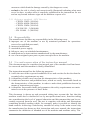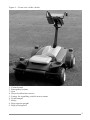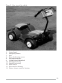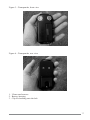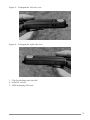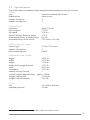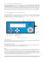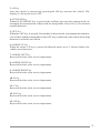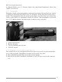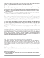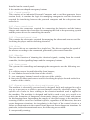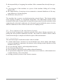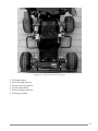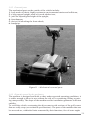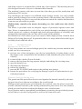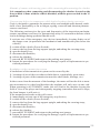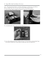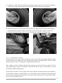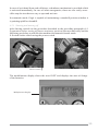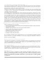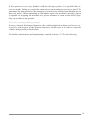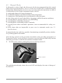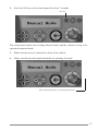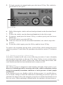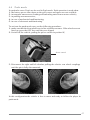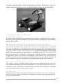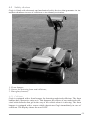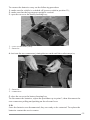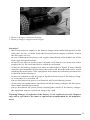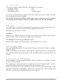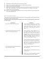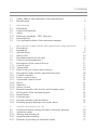
1
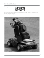
Contents
1
1.1
1.2
Manufacturer identification data
Name, address and trademark of the manufacturer
Identification
3
3
4
2
2.1
2.2
2.3
2.3.1
2.4
2.5
Introduction
Definitions
General information
Safety
Reference standards – EEC Directive
Responsibility
Use and conservation of the instruction manual
5
5
5
5
6
6
7
3
3.1
3.2
3.3
3.4
3.5
3.6
3.7
3.7.1
3.7.2
3.7.3
3.8
3.8.1
3.8.2
3.8.3
3.8.4
3.8.5
3.8.6
3.8.7
3.9
3.9.1
3.9.2
3.9.3
3.9.4
Description, technical data and general operating principles
Description
Equipment
Specifications
Safety rules
Recommendations for driving
General recommendations
Description of the control devices
Control panel
Transponder
Risks in the use of the control devices
Description of the electric and electronic parts
Central controller
Power control circuit
Ultrasound control circuit
Driver
Shunt box
Sensor system
Hazards caused by the electric and electronic parts
Description of the mechanical parts
Internal parts
External parts
Hazards caused by the mechanics
Residual hazards Improper use by the driver
8
8
8
13
14
16
17
17
17
19
19
20
21
21
21
21
21
21
21
22
22
24
24
25
4
4.1
4.2
4.2.1
4.2.2
4.2.3
Specific instructions for use
Preparation before setting off from a stationary position
Automatic mode
Starting and moving off
Stopping and restarting
Hazards of operating in Automatic mode
28
28
29
30
34
35
4.3
Manual mode
37
4.3.1
4.4
4.4.1
4.5
4.5.1
4.5.2
4.6
4.7
4.8
4.8.1
4.8.2
4.9
4.9.1
4.10
4.11
4.12
4.13
4.14
4.15
4.16
4.17
Hazards of operating in Manual mode
Push mode
Hazards of operating in Push mode
Safety devices
Collisions
Emergencies
In case of rain
Parking area
Batteries
Technical specifications of the batteries
Connecting the batteries
Charging the batteries
Battery charger
Tyres
Signalling lamps
Maintenance and cleaning
Transport
Packing
List of the materials used
Dismantling and demolition
Troubleshooting
39
41
42
44
44
45
46
47
47
47
47
49
51
51
51
51
53
54
55
55
56
1.
Manufacturer identification data
1.1 Name, address and trademark of the manufacturer
O.M.G. srl
Via della Tura s/n
56032 Cascine di Buti (PISA)
ITALY
Tel. +39 0587 724762
Fax +39 0587 725160
e-mail: [email protected]
3
1.2 Identification
Name of the product:
Serial number: the vehicle's serial number is on the frame at the bottom of
the bag-support upright.
4
2.
Introduction
2.1 Definitions
The following definitions apply in this document:
1. machine, the mechanical, electrical and electronic parts taken as a whole and
whatever constitutes the product;
2. danger zones, any zone inside and/or in the vicinity of the machine in which the
presence of a person might constitute a health and safety hazard for that person;
3. person at risk, any person who is completely or partly within a danger zone;
4. driver, player, user or operator, the person who interacts with the machine;
5. mobile vehicle, the part of the machine on which the golf bag rests;
6. transponder, the battery-powered portable device that has to be worn by the
driver when the machine is working in automatic mode;
2.2 General information
Putting the machine into service concerns just the use of the machine itself for the
use intended in this document.
This document is directed at professional and non-professional users.
The instructions for use are an integral part of the machine delivery.
ATTENTION! Before using this machine read ALL the instructions.
2.3 Safety
The manufacturer has guaranteed the machine's safety:
1. When the machine is used for its intended use as described in the instructions for
use, which clearly define the purpose for which the machine has been realized
and contain all the information necessary for guaranteeing its safe and proper
use;
2. In case of malfunctioning and faults, the instructions inform and warn the users
about the residual hazards, namely those hazards that cannot be eliminated or
sufficiently reduced through the design and against which the protection devices
are not - or are not totally - effective.
In evaluating the machine's safety, the manufacturer has performed a thorough risk
analysis considering the principle of building in safety, based on the following
principle.
– preventive: the risk is reduced to a marginal value by means of design choices
which eliminate or limit the possibility that a reasonably foreseeable accident
occurs determined not only by the intended use, but also by possible foreseeable
incorrect use, provided of course that this is not brought about the deliberate
intent to cause damage;
– protective: the risk, in this case, is reduced by realising structural protection
5
measures which limit the damage caused by the dangerous event;
– exclusive: the risk is clearly and unequivocally illustrated indicating what must
never be done, or rather what is expressly prohibited in the instructions for use
and on any hazard indicator signs on the machine or parts of it.
2.3.1 Reference standards – EEC Directive
– CEI EN 55022 (1999/06)
– CEI EN 60950 (2004/05)
– CEI EN 55024 (1999/04)
– EN 300.220 - 3 (2000/09)
– EN 301489 - 3 (2002/08)
2.4 Responsibility
The manufacturer declines any responsibility in the following cases:
1. improper use of the machine or use by untrained personnel for operations
reserved to qualified personnel;
2. incorrect installation;
3. unsuitable power supply;
4. failure to carry out scheduled maintenance;
5. modifications or interventions unauthorized by the manufacturer;
6. use of non-original spare parts or parts non-specific to the machine
2.5 Use and conservation of the instruction manual
This document must be considered an integral part of the machine itself and must
be conserved until the machine is finally demolished.
The instruction manual has the following purposes:
1. it tells the user of the expected conditions of use and vouches for the fact that the
essential safety requirements are met;
2. it identifies possible uses based on the characteristics of the machine;
3. it indicates incorrect and prohibited uses, which are easily foreseeable based on
the characteristics of the machine, in order to make their prohibition known by
means of instructions and signs;
4. it identifies foreseeable faults and guarantees the safety requirements are maintained even in the presence of these faults.
This document is drawn up and presented taking into account the fact that the
machine could also be destined to use by non-professional users, therefore taking
into consideration the level of general education and discernment that can be reasonably expected from the user. The text is complete with tables and illustrations
containing detailed wording which, for example, make it possible to identify the
hand controls. Achieving a satisfactory standard of safety is the main reason why
the manufacturer has drawn up this instruction and users manual; the instructions
summarise the definition of intended use of the machine and machine safety. The
6
document is concise so that the user can master the concepts linked to the correct
use the machine simply, quickly and safely. The user's manual covers the entire life
cycle of the machine and satisfies legal and technical requirements concerning
information about the machine; it provides technicians, operators and maintenance
engineers, with useful instructions, information and warnings for carrying out
expected jobs in conditions of safety; it puts the user in the condition to use the
machine correctly and safely and to maintain it in a good state of conservation and
efficiency. Some of the instructions it gives are:
1. already (operation procedures in the various modes) on the machine itself, in a
table on the control panel box;
2. already in the documents provided at the sale.
The manual mirrors the technological level current at the time of the machine’s sale,
which may be updated at a later date.
7
3.
Description, technical data and
general operating principles
3.1 Description
Gogò is a completely automatic mobile machine for the facilitated transport of a
golf bag on the golf course. Basically, it consists of:
• a mobile vehicle consisting of:
– a wheeled mechanical structure;
– a frame that includes a tubular structure for transporting the bag (bag-support
upright), a seat for resting whilst waiting and a thermoformed body;
– an electronic part for driving and safety device management;
– a pair of reducers in CC;
– a power supply unit consisting of two PB-GEL sealed batteries.
• A transponder worn by the player.
Gogò is equipped with mechanisms for detecting possible collisions and emergency
situations.
3.2 Equipment
Gogò is supplied in the following configuration:
– a mobile vehicle complete with frame, body, bag-support upright, front bumper
with protection in sensorized rubber, two DC motors, two front suspension units,
four wheels with rubber rain tyres and alloy discs, an electronic control system
complete with driving management, electrical power system and operating safety
features and a seat;
– A battery-powered transponder.
– two pre-wired batteries;
– an external electronic battery charger with a connecting cable;
– a belt to secure the bag to the frame.
8
Figure 1 – Front view of the vehicle
1
9
8
2
4
2
4
4
7
4
3
5
5
6
1.
2.
3.
4.
5.
6.
7.
8.
9.
Control panel
Emergency buttons
Seat
Player localization sensors
Lamps for signalling vehicle in movement
Front bumper
Body;
Bag-support upright
Bag-securing belt
9
Figure 2 – Rear view of the vehicle
1
4
3
8
4
4
10
2
9
4
11
14
2
13
12
1.
2.
3.
4.
8.
9.
10.
11.
12.
13.
14.
Control panel
Emergency buttons
Seat
Player localization sensors
Bag-support upright
Upright release handwheel
Housing for the bag
Handles for loading
Motor clutch
Electronic box housing
Battery charger connector housing.
10
Figure 3 – Transponder, front view
1
2
Figure 4 – Transponder, rear view
3
1. Ultrasound sensors
2. Battery housing
3. Clip for hooking onto the belt
11
Figure 5 – Transponder, left side view
4
3
Figure 6 – Transponder, right side view
5
3
3. Clip for hooking onto the belt
4. ON/OFF switch
5. LED indicating ON state
12
3.3 Specifications
The main technical, manufacturing and performance parameters are given below:
• Motor
type
separate excitation DC motors
transmission
worm screw
number of motors
2
number of reducers
2
• Performance1
autonomy
about 7.45 mi
typical speed
3.28/ft
top speed
5.24 ft/s
typical distance from the player
5.74 ft
maximum distance from the player 19.68 ft
maximum slope of the terrain
25% front, 10% side
• Electrical power supply
battery type
number of batteries
total installed power
27 A/h, 12V cyclic
2
648 W
• Dimensions and weights
36.24 in
length
width
25.78 in
height
37.00 in
height with upright lowered
15.55 in
track
20.66 in
wheelbase
22.63 in
number of bags carried
1
overall weight under full load approx. 154 lb
121.00 lb
weight without load
70.54 lb
weight without batteries
• Tyres
size
optimum pressure
10 x 4.00-5 tubeless
1.8 bar
1 – Performance depends on the weather conditions and the terrain.
13
3.4 Safety rules
! Before installing the equipment or before any operation on it, this manual
must be read. If the equipment is installed by personnel not employed by the
manufacturer or if they carry out routine and/or extraordinary maintenance
on it, the owner must make sure that the personnel in charge have looked at the
rules contained in this manual.
In order to avoid any risk of accidents the following rules are laid down:
– activate the equipment only after verifying that the installation is satisfactory and
that it complies with the directions given in this manual;
– verify that the labels bearing information about safety are always clearly visible
and in good condition;
– do not switch on the vehicle until it is fully and properly installed;
– do not rest containers with any type of liquid in them on top of the equipment,
even when it is switched off;
– do not carry out maintenance operations inside the vehicle. for this type of operation contact only qualified personnel.
Vehicle safety depends on the care taken by the user when moving it. Excessive
speed is a crucial factor in malfunctions or losing track whilst following the player.
Therefore, the speed limits quoted in the specifications have to be respected and the
safe speed, which depends on factors such as the characteristics of the terrain and
the weather conditions, must never be exceeded.
Gogò cannot be operated in heavy rain. For this reason, do not use the vehicle in
case of rain or when rain is forecast. In the case in which a player is caught out by
the rain on the course, he must stop and switch off the vehicle.
Before activating Gogò, a general check-up of the vehicle is necessary to make
sure that it can be used in the utmost safety. In particular, before switching on
Gogò, the user must check whether the vehicle battery and the transponder battery
are well charged and carefully follow the procedures given in the instructions for
use. Gogò must be switched on standing to one side and not in the direction of
travel, keeping one hand near the emergency devices, to be activated in case an
emergency of any type arises. Before re-activating Gogò after an emergency has
arisen, make sure that the causes of the emergency have been eliminated (in any
case follow the specifications in the following chapters dedicated to emergencies).
The unpractised user must make himself familiar with the vehicle before using it
on the golf course. Gogò has been designed for use in the open field on fine, cut
grass (typical golf course environment). For this reason, it is absolutely forbidden to operate Gogò in automatic mode in closed environments (parking areas,
garages, etc) or in other environments that are not golf courses. During normal
operation, the player must take all steps to avoid the risk collisions by choosing
obstacle-free routes. The user must take care passing over wet routes, avoiding
risks of the wheels slipping on the terrain. Gogò is not designed to travel over
particularly deep or large holes or puddles.
14
IT IS DANGEROUS TO APPROACH DEEP WATER AREAS (PONDS,
STREAMS, BROOKS, ETC.).
N.B.
It is absolutely forbidden to carry people.
The Gogò user must try to avoid travelling in zones where other Gogò machines are
present, driving with care in narrow stretches near people or obstacles; if this is not
possible, the player must proceed with the greatest of care, reduce speed and refrain
from reckless manoeuvres or unsafe steering.
The user may not make any modifications to the vehicle or to the accessories
supplied.
The Gogò batteries contain an electrolyte; in case of contact with the skin and/or
eyes rinse immediately and seek medical advice.
WARNING! Do not install non-approved electrical accessories since they could
course disturbances or damage the on-board electronics as well as making the
warranty void.
15
3.5 Recommendations for driving
Driving Gogò requires a certain knack, as it is different from other vehicles for
transporting golf bags. For this reason, we recommend trying Gogò out in the open
field until you get used to the movements and manage to actually control vehicle
performance (braking, following distance, travel speed, etc.).
The driving system is designed to help learning and make Gogò easier to use. In
any case, a suitable period for learning to drive the vehicle is mandatory before
using it in potentially hazardous situations or in the presence of other people
or obstacles.
To drive Gogò in automatic mode, just put on the transponder hooking it to your
belt, load and firmly secure the bag to the upright and activate the vehicle and transponder according to the starting procedure described in the following paragraphs;
after this, all you have to do is walk in front of machine to be followed gently at a
distance about 6.50 ft.
Once you have reached the ball, to stop Gogò and proceed with your stroke you
may turn off the transponder. Once you have played your stroke, just switch the
transponder back on and follow the ball for the next stroke.
Top vehicle speed is about 5.24 ft/s; travelling at this speed is only recommended if
really necessary. Gogò is designed to travel at a speed of about 1 m/s and autonomy
in this case is sufficient to complete an entire competition course with no problems
(typically an 18-hole course).
To make the most of Gogò's autonomy we recommend:
– driving smoothly and not braking sharply;
– travelling at a moderate pace;
– avoiding, if possible, continuous rises and falls on hills or particularly steep
slopes;
– fully charging the batteries before starting off.
In case the batteries run completely flat on the golf course, electric traction can be
eliminated and the vehicle can be pushed back to destination (see 4.4 Push mode).
16
3.6 General recommendations
The player must observe the rules of the golf course. Going onto the green with
Gogò is prohibited in order to avoid damage to the lawn. For this reason, the player
must leave Gogò near the green in a suitable position that ensures utmost safety. The
player must keep to the routes and passages recommended by those who manage the
golf course and refrain from using Gogò if advised to do so by the course manager.
3.7 Description of the control devices
3.7.1 Control panel
The control panel is located at the front of the vehicle, at the end of the bag-support
upright in an easily accessible position (see figure 2, page 11). The control panel has
the following devices and controls (figure 7):
2
3
4
5
Stand
On
By
Off
1
Ok
M
Esc
C
6 7 8 9
14
10 11 12 13
Figure 7 - Control panel
1. Power switch
When the switch is turned to position I, the vehicle is powered up. When the switch
is turned to position 0, the vehicle is disabled.
2. Multifunction display
The multifunction display gives a real time display of the state of charge of the batteries and the three stages of ON, STAND-BY and OFF.
N.B.
The state of charge of the batteries is a precise and unequivocal reading taken from
a real-time calculation, which depends on the travel and terrain conditions. For instance, after a long climb, the percentage shown could fall considerably and then
rise again after having travelled on the flat or downhill for a while. In any case, the
actual autonomy of the vehicle is guaranteed for about 7.50 mi.
17
3. ON key
Once the vehicle is powered up, pressing the ON key activates the vehicle. The
display (2) shows the word “ON”
4. STAND-BY key
When the STAND-BY key is pressed, the machine goes into the waiting mode, interrupting the transmission of data with the transponder. Press ON (3) to reactivate
normal operation.
5. OFF key
When the OFF key is pressed, the machine is deactivated, interrupting the transmission of data with the transponder. If the OFF key is held down, the front wheels align
themselves with the rear wheels.
6. ARROW UP key
When the Arrow UP key is pressed in Manual mode (see 4.3 Manual Mode) the
vehicle speed increases.
7. ARROW LEFT key
Reserved for after-sales service department.
8. ARROW DOWN key
Reserved for after-sales service department.
9. ARROW RIGHT key
Reserved for after-sales service department.
10. M key
Reserved for after-sales service department.
11. C key
Reserved for after-sales service department.
12. ESC key
Reserved for after-sales service department.
13. OK key
Reserved for after-sales service department.
18
14. Directional handwheel
In Manual Mode (see 4.3 Manual Mode) the directional handwheel allows the
vehicle to be driven.
3.7.2 Transponder
When the switch on the transponder is activated (put in the ON position), the vehicle
is enabled to automatically follow (see 4.2 Automatic Mode) the player in his movements. The transponder must be worn by the player in such a way as to direct the
sensors with which it is equipped towards the vehicle. The transponder is powered
by a 1.5V alkaline battery, housed inside it, which is easy to replace.
1
4
2
3
1.
2.
3.
4.
Ultrasound sensors
Battery housing
Clip for hooking onto the belt
ON/OFF switch
3.7.3 Hazards in the use of the control devices
The control devices are designed and built in such a way as to be so safe and reliable
as to avoid any kind of hazardous situation and in such a way that:
1. they withstand normal-duty stress and external agents;
2. they do not produce hazardous situations in case of logic errors in the manoeuvres.
19
The control panel, located at the front of the vehicle, at the end of the bag-support
upright, is protected against penetration by rain and foreign bodies.
The safety devices are:
1. set out in such a way as to guarantee safe, unequivocal and rapid manoeuvring;
2. situated outside the danger zones;
3. arranged in such a way that operating them does not produce additional hazards:
4. designed or protected so that the potential action cannot occur without an intentional manoeuvre;
5. built in such a way as to resist predictable strain; the emergency stop devices are
standards-compliant and can withstand considerable strain.
Each device is designed and built to consent unequivocal actions. The position and
the travel of the control devices take into account ergonomic principles and the
effort required to operate them is compatible with the action they actuate. The machine is equipped with signals located on the front part of the vehicle.
Of course, while the machine is operating, the player can make sure that there are
no people in danger in the hazard areas. In any case, the control system has been
designed and built so that every time the vehicle moves a visual warning signal is
emitted (signalling lamps).
The person at risk has the time and means to promptly prevent the machine from
starting.
Accidental collisions or using excessive force on the control devices can cause them
to break, which can lead to the accidental activation of the vehicle, but not to its
movement (this always requires a voluntary action by the driver on more than one
device: Power up switch + ON key + ON/OFF switch on the transponder) hence
in conditions of safety for people and property. In these cases, it is compulsory to
deactivate the machine using the emergency buttons.
3.8 Description of the electric and electronic parts
The control electronics consist of a group of control circuits that are supplied already assembled and fitted with the relative electrical interconnections. The electronics can be divided into two distinct parts: one part installed on the frame and one
part installed on the body, connected together by means of two pairs of multipolar
connectors.
Installed on the frame are:
1. the power control circuit, the central controller, the collision sensor and the shunt
control circuit.
Installed on the body are:
1. the control panel, the ultrasound con- trol circuit and ultrasound sensors, and the
signalling lamps.
20
Installed on the control panel:
1. the mushroom-shaped emergency buttons
3.8.1 Central controller
This consists of an industrial Personal Computer and a card that generates lower
tension feeds, it contains the logic for managing emergencies and the electronics
required for interfacing between the personal computer and the subsystems connected to it.
3.8.2 Power control circuit
This houses the connectors required for connecting the batteries and the battery
charger and contains the electronics for managing the feed to the processing system
and the power drivers for controlling the motors.
3.8.3 Ultrasound control circuit
This contains the electronics required for managing the ultrasound sensors used for
localising the player and for detecting obstacles.
3.8.4 Driver
Two power drivers are contained in a single box. The drivers regulate the speed of
the motors according to the commands generated by the central controller.
3.8.5 Shunt box
This has the function of shunting the electrical signals, coming from the central
controller, for the signalling lamps and the emergency buttons.
3.8.6 Sensor system
The systems for controlling and managing the emergencies use the following sensors:
1. a collision sensor located behind the front bumper;
2. two blinkers located at the front of the vehicle;
3. two emergency buttons located on the rear of the vehicle;
4. four pairs of ultrasound sensors used for localising the player located on the four
corners of the vehicle;
3.8.7 Hazards caused by the electric and electronic parts
The machine is electrically powered and is designed, built and equipped in such a
way as to prevent or to allow to prevent hazards caused by electrical energy. The
specific set of rules in force relating to the electrical material used is applied to
the machine. The machine is designed and built in such a way as to avoid or to
reduce the formation of dangerous electrostatic charges and is fitted with means
for discharging them. Interrupting the supply of electrical energy to the machine or
restoring it after a cut-off or variation in power, regardless of the direction, does not
create dangerous situations. An irregularity in the logic of the control circuit or a
failure or deterioration in the control circuit does not create dangerous situations. In
particular, in the aforementioned cases, the following are avoided:
1. unexpectedly starting;
21
2. the impossibility of stopping the machine if the command has already been given;
3. a moving part of the machine or a piece of the machine falling off or being
thrown off;
4. the impossibility of carrying out an automatic or manual shutdown of the any
type whatsoever of moving part;
5. inefficient safety devices.
The machine has a power overload protection circuit (fuses). The design makes
errors during assembly or reassembly impossible. The indications shown on the
terminal blocks make it impossible for specialised personnel to make mistakes when
connecting the electrical conductors. An electrical system inside the power circuitry
inhibits connection to the vehicle in the case of coupling errors.
3.9 Description of the mechanical parts
Gogò has been designed for optimum pursuit of the player during operation, imposing the least possible limitations on him. The result is a mobile vehicle whose
construction design is simple and which requires little maintenance.
3.9.1 Internal parts
The mechanical parts inside the mobile vehicle include:
1. a frame built from a structure of curved tubular iron, whose shape and dimensions are designed to guarantee the utmost safety during normal operation of the
machine's life cycle;
2. two rear driving wheels, with independent motors;
3. two front steering wheels;
4. front wishbone suspension with rubber rebound bumpers;
5. two permanent magnet DC motors with worm screw reducers, with transmission
coupled directly to the wheel hub.
6. steering system by means of an electric actuator.
22
2
2
5
5
1
4
3
3
6
Figure 10 – Mechanical internal parts
1.
2.
3.
4.
5.
6.
Tubular frame;
Rear driving wheels;
Front steering wheels;
Front suspension;
Direct current motors;
Steering system.
23
3.9.2 External parts
The mechanical parts on the outside of the vehicle include:
1. body made of plastic, highly resistant to environmental strains and collisions;
2. a bag-support upright, made of curved tubular iron;
3. joint for adjusting the height of the upright;
4. front bumper;
5. device for unlocking the front wheels;
6. handgrips.
6
2
3
5
1
4
Figure 11 – Mechanical external parts
3.9.3 Hazards caused by the mechanics
The machine is designed and built so that, under expected operating conditions, it
is stable enough to allow its use without the risk of it overturning, falling or moving unexpectedly. The shape of the machine and its installation guarantee sufficient
stability.
To avoid the vehicle overturning the driver must avoid sections of the golf course
that are really steep (see technical specifications). The parts of the machine that can
be accessed are, within the limits consented by their functions, free of acute angles
24
and sharp corners or rough surfaces which may cause injuries. The internal parts are
also designed in such a way as to eliminate these hazards.
The machine's motors take into account the rules that govern the production and
marketing of DC motors.
Any straining by the motors over difficult routes (bumpy terrain, very steep climbs
and in general prolonged use at the operating limits of the machine) may lead to the
motor becoming very hot; in any case the motors are inside the vehicle and therefore
in an area not accessible to people.
Malfunctions caused by the motors becoming very hot could cause the vehicle
to stop.
The motor is provided with an adequate degree of protection against water and
dust. Power is transmitted to each of the rear wheels through a mechanical system
which consists of a reducer, designed and sized with prerequisites of reliability and
strength that contemplate the use that will be made of the machine.
Precautions have been taken to prevent objects which might present a hazard from
falling off or being thrown off. In particular, there is a strap which allows the bag to
be firmly fixed with little effort.
3.9.4
Residual hazards
Improper use by the driver
If very steep routes are crossed at high-speed, the vehicle may become unstable and
in this case it is necessary to:
1. activate one of the emergency stop devices immediately, keeping limbs out of
the danger zone (in particular the mechanical and transmission parts below the
vehicle);
2. switch off the vehicle (Power Switch);
3. remove the bag from the bag-support upright, unhooking the securing strap;
4. open the battery bay;
5. disconnect the batteries;
6. release the clutches;
7. proceed BY PUSHING and return to the parking area/garage;
8. entrust the procedures for verifying the damage, repairs or replacements to specialized personnel.
Hazards caused by moving parts
The guards and the protection devices used against the hazards caused by the moving parts have been chosen according to the actual hazard.
During normal operation no special guards are required, since the player is not subjected to hazards caused by the moving transmission parts and is at a safe distance
which prevents him from reaching the danger zones with his arms.
For all routine and/or extraordinary maintenance operations the specialized personnel will have to use the fixed guards as well as the removable ones.
25
Hazards of contact with moving parts whilst connecting/disconnecting the clutches
It is compulsory that connecting and disconnecting the clutches located on the
front wheels is done with the vehicle disabled, with the power switch in the '0'
position.
Construction defects in components which lead to breakage during operation
Gogò is designed to guarantee the utmost safety and strength under normal conditions of use, particularly as far as fatigue, ageing, corrosion and abrasion phenomena are concerned.
The following sections give the types and frequencies of the inspections and maintenance operations necessary for guaranteeing safety. If construction defects which
lead to breakage during operation should occur:
1. activate one of the emergency stop devices immediately, keeping limbs out of
the danger zone (in particular the mechanical and transmission parts below the
vehicle);
2. switch off the vehicle (Power Switch);
3. remove the bag from the bag-support upright, unhooking the securing strap;
4. open the battery bay;
5. disconnect the batteries;
6. release the clutches;
7. proceed BY PUSHING and return to the parking area/garage;
8. entrust the procedures for verifying the damage, repairs or replacements to specialized personnel.
Breakdown of the transmission system
A breakdown of the transmission system can be caused by the:
1. breakage of one of the two reducer shafts due to a particularly great strain;
2. breakage of parts of the transmission near the wheel (hubs, bearings, etc.).
In these cases from the moment of the breakage, the motor will not be able to transmit movement to its wheel and therefore the machine will only steer on one side.
When operating in AUTOMATIC mode, this will lead to the machine leaving the
field of view of the player and subsequently stopping (remember that until it stops,
the front bumper is still active).
If the transmission breaks on the golf course:
1. immediately activate one of the emergency stop devices;
2. switch off the vehicle (Power Switch);
3. remove the bag from the bag-support upright, unhooking the securing strap;
4. open the battery bay;
5. disconnect the batteries;
6. release the clutches;
7. proceed BY PUSHING and return to the parking area/garage;
8. entrust the procedures for verifying the damage, repairs or replacements to specialized personnel.
26
Hazards caused by contact with the wheels
The rear (traction) wheels always stay inside the silhouette of the vehicle thus avoiding the possibility of contact. The front wheels are used for steering and are small
so as to reduce the risk of collisions from the side. The low speed and weight of the
vehicle means that any damage caused by crushing people's lower limbs will be
limited. However, the driver is required to make sure the conditions of utmost safety
exist before moving Gogò when other people are near the wheels.
27
4. Specific instructions for use
4.1 Preparation before setting off from a stationary position
Before using Gogò, the user must carry out the following procedure:
1. raise the bag-support upright and fasten it using the rear handwheel;
2. verify he has the transponder with the charged battery;
3. leave the parking area in the PUSH mode (see 4.4 Push Mode) and position Gogò
in an open, obstacle-free zone that has sufficient room for manoeuvre;
28
4. couple the right and left clutches pressing on the relative rear wheel couplings
and if necessary turning the relevant wheel until the pin enters properly;
5. If the batteries have been previously removed, place them in their relevant bays
and connect the cables to the power unit (see 4.8.2 Connecting the batteries).
6. load on the bag, taking care to secure it properly with the securing strap.
4.2 Automatic mode
In this mode Gogò can follow the player (who wears the transponder hooked onto
his belt at the rear, taking care to keep the transponder pointing at the vehicle) in the
open field as he moves along the competition golf course.
The vehicle is able to follow the driver keeping at a preset distance (about 6.56 ft)
and modifying its speed according to that of the driver (up to a limit preset in the
installation and testing phase).
If the player decides to stop, Gogò will stop with him, keeping at the preset distance.
If the player wishes to stop Gogò so as to be able to move without being followed
(for instance to play the stroke) he can switch off the transponder or press the Standby key on the control panel.
29
In case of accidental front-end collisions, a shutdown mechanism is provided which
is activated immediately. In case of other emergencies, there are two easily accessible stop devices that are easy to spot and activate.
In automatic mode, Gogò is capable of maintaining a standstill position whether it
is pointing uphill or downhill.
4.2.1 Starting and moving off
After having carried out the procedure described in the preceding paragraph (4.1
Preparation before setting off from a stationary position) the user must carry out the
following procedure to activate the machine in automatic frontal mode:
1. Switch on the vehicle using the power switch.
Power switch
The multifunction display shows the word 'OFF' and displays the state of charge
of the batteries.
Multifunction display
30
2. Press the ON key positioned on the control panel to activate the vehicle in automatic mode.
ON key
Control panel
The multifunction display shows the word 'ON'
Directional handwheel is pointing forwards
Attention!
Make sure that the directional handwheel is pointing forwards. In this situation, the
vehicle is ready to follow the player in automatic frontal mode. If the word 'ON'
does not appear on the display consult section 4.17 Troubleshooting.
31
3. Switch on the transponder, putting the switch on the side in the ON position.
ON/OFF Transponder Switch
The system is activated: the vehicle and the transponder begin to communicate with
each other and the position lamps flash. Verify that the LED located on the side of
the transponder is on (green flashing light).
Transponder operating state LED
At this point the vehicle is ready to move in automatic mode.
32
Put on the transponder, behind your belt, stand in front of the vehicle and walk.
Gogò will faithfully follow the player.
Correct position of the transponder, worn behind the belt, with the sensors pointing
towards the vehicle.
Flashing position lights
The transponder if fitted with an acoustic signaller which warns the player if the signal from the vehicle is lost. In this case the user must stop and approach the vehicle
until he comes back into the signal reading range. The transponder acoustic signal
will cease and the player will be able to continue with the automatic movement.
33
4.2.2 Stopping and restarting
Once you have played your stroke and reached the ball, to stop Gogò just stop yourself. The vehicle will position itself at the preset distance from the player (about 6
ft) and will remain waiting.
To stop the vehicle from following the player (for example if he has to go onto the
green), the user can choose between two options:
1. Switching off the transponder, putting the switch in the OFF position.
ON/OFF Transponder Switch
Communications between the vehicle and the transponder are interrupted and the
vehicle will stay in its position.
Once you have played your stroke, to reactivate the communications system just
turn the transponder back on putting the switch in the ON position, stand in front
of the vehicle (not more than 10 ft away) point the sensors towards the vehicle and
continue your walk.
If the procedure described does not work, consult section 4.17 Troubleshooting.
34
4.2.3 Hazards of operating in Automatic mode
Activation of Automatic mode only occurs following execution of some voluntarily
and determined operations on the part of the driver. Failure to carry out the activation procedure means the vehicle will not start.
When the lamps start to flash, indicates that the machine has been initialised and
is ready to set off. Movement of the machine in automatic mode can be blocked
switching off the transponder.
Switching off the transponder the vehicle stops but still remains switched on, ready
to set off again as soon as the driver activates the transponder again. The player can
move around in front of the vehicle with his back to it (the transponder must always
be directed towards the vehicle) following trajectories that are as far as possible
linear; in case of particularly tight turns the driver must curb his speed and check
whether the vehicle has maintained the desired trajectory. If not, the driver must go
back and restart the pursuit procedure avoiding the difficult stretches in the route.
The machine is capable of following the driver adapting itself to his speed up to the
threshold preset in the installation and assembly phase.
Breakdown due to malfunctioning of the localisation system
These breakdowns are caused by:
– unsuccessful communication between the transponder and the central controller
on-board the vehicle;
– damage to the system of receivers located on the vehicle;
– electric cables becoming disconnected;
– mechanical breakage of the sensors;
– malfunctioning in case of rain;
– breakage of the electrical parts.
As a result the machine may respond slowly or in a discontinuous manner and the
driver will have to stop the machine, if necessary using the immediate shutdown
devices in case of danger.
External influences on the electrical equipment
The electronic apparatus are standard-compliant where susceptibility from external
electrical equipment is concerned and in any case any malfunctioning of the electronic systems makes the vehicle stop.
Errors in the software
The software is designed using the most modern operation simulation and verification platforms. To guarantee the utmost safety, the emergency stop devices are managed by special control electronics, not by the software.
Operator errors
The driving system is designed to help learning and make Gogò easier to use.
However, a suitable period for learning to drive the vehicle is mandatory before
using it in potentially hazardous situations or in the presence of other people
or obstacles.
35
If the operator is not very familiar with the driving system, it is possible that errors are made, failing to control the manoeuvres and setting an excessive speed. To
guarantee the utmost safety, the emergency stop devices and the front bumper are in
any case active. When operating in Automatic mode, the machine's driving system
is capable of stopping the machine at a preset distance as soon as the driver slips,
trips up or falls to the ground.
Excessive weaving whilst operating
In case of nearly discharged batteries, the vehicle might slow down and weave excessively with respect to the desired trajectory. In this case it is better to stop the
vehicle and proceed in Push Mode.
For further information and explanations, consult section 4.17 Troubleshooting.
36
4.3 Manual Mode
In this mode, to drive Gogò, the driver uses the devices integrated into the control
panel (Directional handwheel, Arrow UP and Arrow DOWN keys) without using the
transponder. Manual mode serves to carry out some particular operations or when it
is not possible to use Gogò in automatic mode, such as:
1. transponder battery becomes discharged;
2. accidental breakage or malfunctioning of the transponder;
3. coming out of the parking area or going back in after the game;
4. after being stuck in sand, wheelslip or stopping in difficult terrain conditions;
5. crossing narrow passages that are very demanding;
6. crossing places with many obstacles;
7. crossing places with many people or animals;
8. crossing areas where automatic operation is not recommended for safety reasons;
9. steep slopes that are impossible to pass over in automatic mode (see 3.3
Specifications).
In manual mode, the vehicle is capable of maintaining a standstill position whether
it is pointing uphill or downhill.
After having carried out the procedure described in the preceding paragraph (4.1
Preparation before setting off from a stationary position) the user must carry out the
following procedure to activate the machine in manual mode:
1. Switch on the vehicle, putting the power switch in position 'I';
Power switch
The multifunction display shows the word OFF and displays the state of charge of
the batteries.
37
2.
Press the ON key on the control panel for about 7 seconds.
ON key
The control panel shows the wording Manual Mode and the vehicle is ready to be
operated in manual mode.
3.
Make sure there are no obstacles in front of the vehicle.
4.
Make sure that the directional handwheel is pointing forwards.
Directional handwheel is pointing forwards
38
5.
To begin operation in manual mode, press the Arrow UP key. The vehicle begins to move at low speed.
Arrow UP key
6.
Walk, following the vehicle with one hand positioned on the directional handwheel.
7. To drive the vehicle, turn the directional handwheel to the left or right.
8. To increase speed press the Arrow UP key; to reduce speed, press the Arrow
DOWN key
9. To stop the vehicle, press the OFF key.
10. If the user does not turn the directional handwheel, the vehicle stops after
16.40 ft.
11. To start the vehicle again, press the ON key and the Arrow UP key.
To return to the Automatic driving mode, switch off the vehicle turning the power
switch to position '0' and follow the procedure described in section 4.2 Automatic
Mode.
4.3.1 Hazards of operating in Manual mode
Activation of manual mode only occurs following execution of some voluntarily
and determined operations on the part of the driver. Failure to carry out the activation procedure means the vehicle will not start. When the lamps start to flash, indicates that the machine has been initialised and is ready to set off.
Operator errors
The driving system is designed to help learning and make Gogò easier to use.
However, a suitable period for learning to drive the vehicle is mandatory before
using it in potentially hazardous situations or in the presence of other people
or obstacles.
If the operator is not very familiar with the driving system, it is possible that errors are made, failing to control the manoeuvres and setting an excessive speed. To
guarantee the utmost safety, the emergency stop devices and the front bumper are in
any case active. When operating in Manual mode, the machine's driving system is
39
capable of stopping the machine at a preset distance as soon as the driver slips, trips
up or falls to the ground.
External influences on the electrical equipment
The electronic equipment is standard-compliant where susceptibility from external
electrical equipment is concerned and in any case any malfunctioning of the electronic systems makes the vehicle stop.
Errors in the software
The software is designed using the most modern operation simulation and verification platforms. To guarantee the utmost safety, the emergency stop devices are managed by special control electronics, not by the software.
Excessive weaving whilst operating
In the case of nearly discharged batteries, the vehicle might slow down and weave
excessively with respect to the desired trajectory. In this case it is better to stop the
vehicle and proceed in Push mode.
40
4.4 Push mode
In particular cases Gogò can be used in Push mode. Push operation is used when:
1. the battery power runs down on the golf course and spares are not available:
2. in transport manoeuvres (loading and unloading onto/from a motor vehicle);
3. in parking area manoeuvres;
4. in case of mechanical malfunctioning;
5. in case of electronic malfunctioning.
To activate the push mode carry out the following procedure:
1. make sure that the front wheels are in line with the rear ones. If the wheels are not
lined up, press the OFF key until they are aligned
2. Switch off the vehicle, putting the power switch in position '0';
Power switch
3. Disconnect the right and left clutches pulling the relative rear wheel couplings
until the pin is fully disconnected;
In this configuration the vehicle is free to move and ready to follow the player in
push mode.
41
Attention! In push mode, vehicle steering does not work. Therefore, to steer the
vehicle, the front wheels have to be lifted slightly levering on the handgrips.
4
4
4. Handgrips
4.4.1 Hazards of operating in Push mode
Disconnecting the clutches
As soon as the clutches are disconnected, the vehicle is completely free to move;
therefore, this operation must be carried out under conditions of total stability
and on flat terrain.
Impossibility of stopping the machine under the best possible conditions
The push handling procedure, starting from the deactivation of the electrical systems
and the disconnection of the mechanical transmission and both wheels (clutches)
can lead to difficulty in controlling the vehicle on particularly steep uphill and/or
downhill stretches of the course. Therefore, it is absolutely compulsory that uphill
and/or downhill stretches of the course are avoided, and if this is not possible, the
driver must make sure, in advance, of his capacity to push and brake, considering the
weight of the vehicle. If the driver does happen to lose control of the vehicle, he will
be able to quickly get off the trajectory taking care to direct the vehicle into an area
where there are no people, warning anyway others of the danger of the situation.
Other external influences (gravity, wind, etc.)
The vehicle is heavy enough to stop it being moved accidentally by the wind. The
driver must never leave the vehicle standing near a downhill stretch (in such a circumstance, even a slight shift of position due to strong wind could make it unstable
and cause undesired movement of the vehicle).
Operator errors
The procedure for disconnecting the transmission is simple; however a suitable period for learning to drive the vehicle is mandatory before using it in handling situations using push mode.
42
Hazards connected to pushing loads
Before setting off, the driver must make sure that he is fit and healthy enough to
push the machine if it breaks down, whatever the current environmental and atmospheric conditions.
43
4.5 Safety devices
Gogò is fitted with electronic and mechanical safety devices that guarantee its immediate shutdown in case of collisions or involuntary activation.
3
3
2
1
1. Front bumper;
2. Sensor for detecting front-end collisions;
3. Emergency buttons;
4.5.1 Collisions
Gogò is equipped with a front bumper for detecting undesired collisions. The front
bumper has a protective strip on it. This dampens the effects of any undesired collisions with obstacles that get in the way of the vehicle when it is moving. The front
bumper is equipped with a sensor which deactivates Gogò immediately in case of
collisions. The display shows the word 'OFF'.
44
In case of undesired collision with an obstacle, carry out the following procedure
to reactivate Gogò:
1. Verify the extent of the damage and if need be, advise the golf course staff;
2. If there is no damage, move the vehicle manually away from the situation of
danger;
3. Press the ON key on the control panel;
4. The multifunction display shows the word 'ON';
5. Set off again in Automatic mode in conditions of safety.
If the procedure described does not work, consult section 4.17 Troubleshooting
4.5.2 Emergencies
To handle any emergencies, Gogò is equipped with emergency stop devices which:
1. are clearly identifiable, highly visible and easy to reach (in the rear of the vehicle);
2. stop the dangerous process in the shortest time possible, without creating additional hazards;
3. allow some safeguard actions to be taken (escaping to the side, etc.).
Once the emergency stop device is operated following an order to shut down, this
order is retained by the emergency stop device which is blocked until released; the
device cannot be blocked without it generating a command to shut down; the device
can only be released with a special manoeuvre that does not restart the machine,
but only authorises it to be set back at work (by pressing the ON key on the control
panel after the mechanical release). The emergency buttons comply with the rules
(red colouring, yellow background underneath, self-blocking operation, which prevents automatic start-up of the equipment when the button is released). The emergency stop buttons are controlled by control electronics, not by the software. When
the machine stops, its drift from the stop position, for whatever cause apart from
the operation of the control gear, is not great enough to create hazards for people
in the area. The machine is designed in such a way that when the drift occurs the
uncontrolled weaving of its center of gravity does not jeopardise stability or subject
its structure to excessive strain.
N.B. If the player becomes aware of situations of danger or realises there is a
malfunction which may cause damage to people or property, he must immediately press one of the two red buttons on the rear of the vehicle.
45
Once the emergency devices are activated, the vehicle deactivates immediately and
the multifunction display shows the word OFF. To reactivate Gogò after having
pressed the emergency button, carry out the following procedure:
1. release the emergency button pressed previously by pressing the red key;
2. get into a safe situation;
3. press the ON key on the control panel;
4. set off again in Automatic mode in conditions of safety.
If the procedure described does not work, consult section 4.17 Troubleshooting
4.6 In case of rain
Gogò has been designed to work on dry terrain and in low humidity weather conditions; therefore, using Gogò in case of rain is not recommended. If the player is
caught out by the rain during the match on the golf course, to maintain conditions of
safety for himself and for others, he must carry out the following operations:
1. stop immediately;
2. switch off Gogò, putting the power switch in position '0';
3. put the transponder in a sheltered place;
4. prepare for an immediate return in push mode as soon as the weather allows it.
It is not recommended to use Gogò if rain is forecast.
The sensors located on the vehicle are protected against splashes of water, while
the sensors on the transponder are housed in such a way as to limit damage caused
by the penetration of water. If the player continues to walk ahead in the rain in
Automatic mode, the sensors on the transponder could become damaged and stop
working, thus causing the machine to malfunction. If Gogò accidentally falls into
water, immediately press one of the emergency stop devices; get away from the
vehicle and call the personnel straight away, specifying that the machine is powered
by two Piombo Gel batteries which give a total supply voltage of 24V.
46
4.7 Parking area
Coming out of the parking area or going back in after the game must be done in Push
mode (see Section 4.4 Push Mode).
After having parked the vehicle, make sure it is actually switched off, checking that
the power switch is in position '0'. Verify that the transponder is also switched off
(power switch in the OFF position).
Warning: Gogò has been designed for use in an open environment. For this
reason, it is absolutely forbidden to operate Gogò in Automatic mode in closed
environments (parking areas, garages, etc.).
4.8 Batteries
Batteries are supplied along with Gogò. Battery-replacement operations must be
carried out by specialised personnel. For any battery-replacement operations contact
the service center.
4.8.1 Technical specifications of the batteries
Gogò is set up to work with PB-GEL traction batteries, each of which has the following specifications:
– Voltage rating
12V
– Capacity rating
35Ah / 20 Hr
– Number
of
batteries
2
– Battery dimensions
7.71 x 5.11 x 6.61 in
– Maximum charging current
3.5A
– Operating temperature
from -10°C to 60°C
4.8.2 Connecting the batteries
Gogò is supplied with special connecting cables to connect the batteries with the
power control circuit. The housing for the batteries is situated and the batteries installed in such a way as to avoid, as far as possible, electrolyte being projected
onto the operator even if the machine overturns and/or to avoid the accumulation of
fumes near the user. The machine is designed and built so that the two batteries can
be connected with a purpose made device that is easy to reach.
47
To connect the batteries carry out the following procedure:
1. make sure the vehicle is switched off (power switch in position '0');
2. make sure that the bag-support upright is vertical.
3. open the cover to the battery housing bay;
1
2
1. cover to the battery bay
2. batteries
4. Activate the two connectors joining the two ends until the socket snaps in;
3
2
2. batteries
3. connectors
5. close the cover to the battery housing bay.
To disconnect the batteries, repeat the procedure up to point 3, then disconnect the
two connectors pulling and pushing on the relevant lever.
N.B.
Once the batteries are disconnected, they are ready to be extracted. To replace the
batteries contact the service center.
48
4.9 Charging the batteries
Attention!
During battery charging, take the precautions relative to the use of electrical equipment. Charging the batteries creates a low-level emission of hydrogen: so it is a
good idea to provide sufficient ventilation if charging is carried out in a covered
area. The battery charger power plug MUST be connected to a socket fitted with an
earth contact. For information about charging refer exclusively to the user's manual
of the battery charger supplied.
In general, interventions of any type on the vehicle are prohibited while the
batteries are being charged.
Particularly prohibited are washing, starting or moving the vehicle.
If working on the vehicle is necessary:
– disconnect the battery charger from the mains;
– if the power cables are damaged, request assistance from qualified personnel;
– the vehicle must be positioned in such a way that the mains power socket is easy
to reach during charging.
Charging the batteries must be carried out in aerated rooms without any flames and
sparks.
In particular, charging must not be done in the vicinity of boiler rooms or electrical
contactors.
Observing the maintenance conditions of the batteries is compulsory. To charge the
batteries, Gogò is supplied with an external battery charger complete with a cable to
connect the vehicle to the mains power supply.
To recharge the batteries carry out the following procedure:
1. make sure the vehicle is switched off (power switch in position '0');
2. insert the battery charger connector in the relevant housing situated in Gogò's
rear end;
3. connect the battery charger to the mains;
4. wait until the batteries are fully charged (green light on the battery charger
LED).
The average charging time is about 10 hours.
49
1
2
1. Battery charger connector housing
2. Battery charger (supplied with Gogò)
Attention!
– the electrical power supply to the battery charger must match that quoted on the
data plate. In case of doubt about the electrical power supply available, consult
the after-sales service.
– in case of damage to the power cord, replace immediately with another one of the
same type and specifications.
– do not lay any objects on the power cord and verify that it is not in an area where
people pass by. the cord must not be rolled up or knotted.
– do not use the battery charger near water or other types of liquid. If water should
enter the unit, immediately disconnect the power cord from the wall socket, avoid
touching the metal parts of the equipment and contact the technical personnel for
a check-up before reusing it.
– do not rest containers with any type of liquid in them on top of the battery charger, even when it is switched off.
– always disconnect the power cord from the wall socket during storms.
– do not carry out maintenance operations inside the battery charger: for this operation contact qualified personnel.
– always disconnect the power before cleaning the outside of the battery charger:
this operation must be carried out using a dry cloth.
Warning! Danger of explosion if the battery is not replaced correctly. Replace
only with a type that is the same or equivalent recommended by the manufacturer.
50
4.9.1 Battery charger
The battery charger supplied has the following specifications:
– charging voltage
24V
– maximum current
3.5 A
– full charging time
10 hours approx.
It is a total automatic battery charger with control microprocessor, suitable for both
fast charging and trickle charging.
For further information and the safety rules, refer exclusively to the technical
instructions for the battery chargers supplied enclosed with this document.
4.10 Tyres
It is important to periodically check the tyre pressure and, if necessary, adjust it by
going to a service center or with the help of qualified personnel.
Optimum tyre pressure is 1.8 bar.
Attention!
Incorrect tyre inflation pressures translate into abnormal wear of the treads, which is
bad for safety, reduces performance and reduces autonomy.
It is dangerous to use Gogò with worn tyres.
Entrust wheel repairs and replacements to specialised service centers.
4.11 Signalling lamps
The two signalling lamps are located on the front part of the vehicle and are a prime
factor in safety.
While using Gogò, the user must verify that the signalling lamps are working properly. Entrust repairs and replacements of the signalling lamps to specialised service
centers.
4.12 Maintenance and cleaning
All maintenance operations must be done with the machine at a standstill and with
the power disconnected.
The maintenance operations must be carried out by specialised personnel, suitably
trained and with a precise knowledge of how the machine works.
Given its particular use in the open field, Gogò is bound to get dirty during normal
operation, although it is designed to reduce to a minimum any effects arising from
dirt that is present around mechanical and electrical parts.
51
Cleaning operations must be carried out by specialised personnel, taking great care
to protect the most delicate external parts (sensors) and avoiding damage of any
type. Below is a maintenance and cleaning schedule:
Operation
Periodicity
Competence
Battery maintenance
every 70 km
(about 10 matches)
Service center
Battery replacement
1000 recharging
cycles
Service center
Transponder battery
replacement
every 20 running
hours
User/Service center
Battery charging
every 10-12 km
(end of match)
User/Service center
Tyre check
every 70 km
(about 10 matches)
User/Service center
Instrumentation check
every 20 matches
Service center
Lamps replacement
according to need
Service center
Tightening of bolts
every 70 km
(about 10 matches)
Service center
Suspension adjustment
every 70 km
(about 10 matches)
Service center
Vehicle inspection
every 30 matches
Service center
Outside cleaning
according to need
User/Service center
Cleaning internal parts
according to need
Service center
Reducer lubrication
every 200 km
(about 30 matches)
Service center
Motor brushes
every 200 km
(about 30 matches)
Service center
Putting out of service
at the end of the life
cycle
Service center
52
4.13 Transport
Gogò is a machine that can be transported safely, designed to be stored safely and
without deterioration. The weight, the dimensions and the shape of the machine or
its various elements allowed it to be lifted by hand by at least two adults (one on
each side). The machine is equipped with handholds located on its sides which make
it easy to lift. Gogò can be loaded into an ordinary motor vehicle, once the capacity
of the boot, considering the dimensions and the weight, has been ascertained (see
3.3 Specifications).
To transport Gogò the following operations are necessary:
1. make sure the vehicle is switched off (power switch in position '0');
2. unload the bag;
3. unscrew the handwheel that locks the bag-support upright;
4. lower the bag-support upright;
5. lock the bag-support upright in the closed position;
6. disconnect the clutches of the front wheels.
At this point Gogò is easy to manoeuvre in push mode and can be loaded by two
adults into a sufficiently large boot.
Attention! Make sure the vehicle is well anchored in the boot and reconnect the
clutches to the front wheels so that it does not move around.
Handwheel for unlocking
View of the vehicle with bag-support
upright lowered, ready for transport
The vehicle is fitted with four handles, one on each side, to hold when lifting.
53
Attention!
– considering the size and weight of the machine, transport and handling operations must be carried out by specialised personnel; failure to observe this warning
can cause physical injuries to people and damage to the vehicle itself;
– equipment fitted with wheels must be handled with care;
– the vehicle contains parts that are susceptible to vibrations and/or knocks: the
utmost care must be taken during handling and transport;
– Lifting the machine with ropes or straps is prohibited since there are not special
anchoring points;
4.14 Packing
The packing procedure for the machine requires it to be placed in a stiff wooden or
cardboard container capable of containing the equipment supplied with it (transponder, battery charger). Gogò must be packed with the bag-support upright lowered to reduce its dimensions to a minimum. The container must be marked with the
words TOP and FRAGILE.
Attention!
The packing procedure must entail special care in protecting the sensor systems
located on the four sides of the vehicle.
1
1
1
2
1
2
1. sensor system parts of the vehicle
2. handles for loading
54
4.15 List of the materials used
The materials used for building the machine or the products used and originated during its use do not present health and safety hazards for people exposed to it.
1. Iron
– Frame
– Plates and supports
– Front suspension wishbones
– Rear suspension wishbones
– Bushes
– Shafts/hubs
– Min tubular upright
– Bag support tube
– Upright rotation shaft
– Front bumper with bracket
2. Steel
– Ironmongery
– Transmission shafts
– Flanges
– Bearings
– Springs
3. Stainless Steel
– Bolts and nuts
4. Bronze
– Steering bushes
– Wheel hub bushes
6. Rubber
Suspension units
-Tyres
-Bag support
-Front bumper
7. Copper
-Motor windings
-Electronic conductor
-Electronic cards
8. Plastic
-Body (ABS)
-Electronic boxes (ABS)
-Electronic cables (PVC)
-Transponder (ABS)
– Upright release handwheel (PVC)
9. Fabric
– Bag-securing belt
10. Electrical material
– Electronic components
– Electrical components
5. Aluminium
-Bodies of reducers and motors
-Wheels discs
-Wheels hubs
4.16 Putting out of service, dismantling and demolition
Gogò is a simple, sturdy and long-lasting machine. In case it should be dismantled
and demolished, the following measures should be adhered to:
1. disconnect and remove the batteries;
2. remove the system that protects against collisions (front bumper);
3. disconnect the clutches and free the motors;
4. disconnect the two motor-driven reducers pouring their contents into a special
container.
55
5.
6.
7.
8.
disconnect all the cables of the electrical system;
remove the sensors located on the four sides from the body;
remove the body from the frame;
disassemble the frame, the suspension units, the bolts and nuts and the wheels
and collect and dispose of the materials separately according to their type;
9 contact specialized personnel;
10. follow the requirements laid down by the current legislation concerning waste
recycling and disposal.
4.17 Troubleshooting
This section lists the causes of the vehicle not working properly and suggests to the
user how to remove these causes.
If the procedures described do not make the vehicle work properly, contact the
service center.
Problem
– The vehicle does not switch on
Solution
– Check that the connectors – by means
of the batteries being activated – are
connected with the power switch
(see 4.8.2 Connecting the batteries
page 73)
– The Control panel shows the word
'OFF' even after the ON key
– Check that the front bumper is in
the right position and that it is not
pressing on the microswitch that is
tripped when a collision is detected.
Push the bumper forward and put it
back in the right position. Press the
ON key on the control panel.
– Check that the emergency buttons on
the rear of the vehicle are not active.
Release the emergency buttons until
they are properly freed (see 4.5.2
Emergencies page 69)
– The vehicle does not follow the player in Automatic mode
– Check that the control panel shows
the word 'ON'.
– Check that the transponder has been
switched on.
– Make sure the transponder sensors
are pointing towards the vehicle.
56
– The vehicle is weaving or behaving
irregularly.
– Check the state of charge of the
vehicle batteries.
– Check the state of charge of the
transponder battery.
– Check that the traction clutches
of the rear wheels are properly
connected. (see 4.1 Preparation
before setting off from a stationary
position page 44).
– Check the state of charge of the
vehi- cle batteries.
– Check the state of charge of the
transponder battery.
– Check that the traction clutches
of the rear wheels are properly
connected. (see 4.1 Preparation
before setting off from a stationary
position page 44).
– Check that the directional handwheel is pointing forwards (see
4.2.1 Starting and moving off page
47).
– Check the tyre pressure is correct
(see 4.10 Tyres page 80)
57
All product illustrations are based upon current information at the time of the
publication approval. O.M.G. srl reserves the right to make changes from time to
time, without notice or obligation, in specifications, materials and to change or
discontinue models, which are considered necessary to the purpose of product
improvement or for reasons of design and/or marketing.
58