1
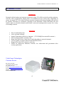
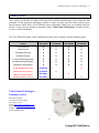
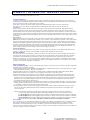
5.8GHz All Weather 8 Channel Series Manual Rev. K
It’s About Real Time
5.8GHz All Weather 8 Channel Series
Manual Rev-K
OWNER’S MANUAL
VideoComm Technologies – “The Freedom of Wireless”
(888) 379-2666 US Toll Free
(905) 339-0366 Phone
(905) 339-1776 Fax
http://www.VideoTransmitters.com/
1
5.8GHz All Weather 8 Channel Series Manual Rev. K
TABLE OF CONTENTS
TABLE OF CONTENTS ..................................................................................................2
SAFETY NOTICES...........................................................................................................3
INTRODUCTION .............................................................................................................4
Advantages
………………………………………………………………………………………………………..4
PARTS LIST ......................................................................................................................5
PRE INSTALLATION......................................................................................................6
Site Evaluation............................................................................................................................................6
Identify line-of-sight ..............................................................................................................................6
Up & in the clear....................................................................................................................................6
Ground Plane .........................................................................................................................................6
Trees Grow! ...........................................................................................................................................7
Unusual Traffic ......................................................................................................................................7
Things that block transmission ............................................................................................................11
Alignment & GPS Use.........................................................................................................................11
Tools Required..........................................................................................................................................12
Opening & Closing The All Weather Enclosure.......................................................................................13
Video Cable Installation & Termination ..................................................................................................14
Video and Audio Cable Installation & Termination.................................................................................15
Terminating External Antenna Cable......................................................................................................16
Terminating External Antenna – Video – Audio Cables.........................................................................16
Unused Grommet Seals ............................................................................................................................17
Power Supply Connection ........................................................................................................................18
Power-Up Device .....................................................................................................................................19
Channel Selection.....................................................................................................................................20
Antenna Polarization................................................................................................................................21
Multiple Link Antenna Polarization .........................................................................................................24
Conducting a Bench Test..........................................................................................................................25
INSTALLATION.............................................................................................................27
Pole Mounting the 5.8GHz All Weather Series ........................................................................................27
Wall Mounting the 5.8GHz All Weather Series ........................................................................................30
Enclosure Alignment and Positioning ......................................................................................................31
TIPS & TROUBLE SHOOTING...................................................................................32
OPTIONAL PRODUCTS & ACCESSORIES .............................................................34
SPECIFICATIONS .........................................................................................................35
WARRANTY INFORMATION/ TERMS & CONDITIONS ...36
2
5.8GHz All Weather 8 Channel Series Manual Rev. K
SAFETY NOTICES
I. THIS DEVICE COMPLIES WITH FCC RULES PART 15. OPERATION IS SUBJECT
TO THE FOLLOWING TWO CONDITONS:
(1)
(2)
This device may not cause harmful interference, and
This device must accept any interference, including interference that
may cause undesired operation of the device
II. In order to comply with the FCC/IC adopted RF exposure requirements, this transmission
system will be installed by an authorized professional installer of VideoComm
Technologies. Installation of all antennas must be performed in a manner that will provide
at least 23cm clearance from the front radiating aperture, to any user or member of the
public.
III. This is NOT an intrinsically safe device. Do not take into area where intrinsic safety is
required. Bodily harm may result if warning is ignored.
IV. DO NOT OPERATE TRANSMITTER WITHOUT ANTENNA CONNECTED TO
ANTENNA PORT. Failure to do so will result in damage to the unit and void the
warranty.
V. DO NOT OPERATE THE TCO-5800 SYSTEM WHEN the Transmitter & Receiver are
closer than ten feet to each other. The devices may not work properly and permanent
damage can occur.
VI. The TCO-5800 has been certified by the FCC for use with other products without any
further certification (as per FCC section 2.1091.) Changes or modifications not expressly
approved by VideoComm Technologies could void the user’s authority to operate the
equipment.
3
5.8GHz All Weather 8 Channel Series Manual Rev. K
INTRODUCTION
Introduction
Designed with the harshest environments in mind, the robust TCO-5808 series delivers high resolution,
real time video in applications ranging from a few hundred feet up to many miles, depending on
system. Its rugged IP-67 all-weather enclosure transmits in applications where trenching cable may not
be possible, convenient or economical. Operating in the unlicensed 5.8GHz ISM band, this unit
features eight user selectable channels and includes a universal mounting bracket system for a variety
of mounting scenarios.
Advantages
•
•
•
•
•
•
•
•
Easy to install and operate.
8 user selectable channels.
Internal Transmitters & Receiver Antennas. ( TCO-5808Q9 has external Rx antenna )
Delivers high resolution, real time video
Range from 2000 feet to 4 miles line of sight (depending on system & antenna)
Less susceptible to wireless data networks and other devices
Rugged all weather IP-67 protective enclosure.
Perfect for commercial, industrial, scientific, law enforcement and government video
security applications.
VideoComm Technologies
Customer Service
Bus (905)-339-0366
US Toll Free 888-379-2666
Fax (905)-339-1776
E-mail- [email protected]
Web Site- www.VideoTransmitters.com
Monday - Friday 8:30am- 5:30pm
Eastern Standard Time
4
5.8GHz All Weather 8 Channel Series Manual Rev. K
PARTS LIST
The 5.8GHz All Weather 8 Channel Series has been carefully manufactured, tested, inspected and
packaged. Please inspect the packaging carefully to ensure you have received all the necessary parts
and accessories listed. Refer to the following chart to determine which parts are included with your
product. If any parts are missing or damaged, contact VideoComm Technologies, Customer Service
or your re-seller immediately.
The TCO-5800 All Weather Video Transmission system comes complete with the following items:
PARTS
TCO-5808T3
TCO-5808R6
TCO-5808Q4
TCO-5808Q9
1 X Transmitter Unit
X
X
X
X
1 X Receiver Unit
X
X
X
X
4 X Grommet Seals Plugs
X
X
X
X
8 X Plastic Lid Screws
X
X
X
X
2 X Universal Mounting Brackets
X
X
X
X
2 X 12VDC 500mA Power Supplies
X
X
X
X
3dB Internal Transmit Antenna
X
X
X
X
6ft. LMR-196NSM Antenna Cable
OPTIONAL
6dB Internal Receiver Antenna
OPTIONAL
14dB Internal Receiver Antenna
OPTIONAL
29dB External Receiver Antenna
OPTIONAL
X
X
X
X
VideoComm Technologies
Customer Service
Bus (905)-339-0366
US Toll Free 888-379-2666
Fax (905)-339-1776
E-mail- [email protected]
Web Site- www.VideoTransmitters.com
Monday - Friday 8:30am- 5:30pm
Eastern Standard Time
5
5.8GHz All Weather 8 Channel Series Manual Rev. K
PRE INSTALLATION
Site Evaluation
Identify line-of-sight
Although wireless video transmission may seem like a viable option for a particular application at first
glance, there are many considerations. Is there a clear, unobstructed view between the transmitter and
receiver? Are there any other devices that may cause interference? Depending on the height of the
building, tower or structure, you must consider the path that the wireless video will travel between the
transmitter and receiver. Line-of –sight is defined as a clear and unobstructed view between the
transmitter and receiver.
Up & in the clear
To realize the optimum distance for your VideoComm Technologies wireless devices, “give them
some air”. The radio waves coming from your TCO-5800 system antennas do not shoot out like a laser
beam, rather they radiate from the antenna like a flash light beam. Therefore the transmitter and
receiver should both be up and in the clear. A good rule of thumb is to mount the devices at least 15 to
20 feet above obstructions, like the roof of a building, the roofs parked cars in a parking lot, or top of a
fence line.
See Figure 2.
Ground Plane
If the radio devices are not mounted high enough above obstructions, the signal strength will be
seriously reduced; therefore your distance will be reduced. The signal will literately bounce up and
away from your intended target. This is known as a negative ground plane effect. The ground plane
could not only be the ground you stand on, but could also be the rooftops of cars or distant buildings.
See Figure 3. If we have a choice, place the transmitter/receiver enclosures, or if external antenna, on
the edge of the roof looking AWAY from the building, rather than installing them in the middle of the
roof , shooting across the top of the roof. See Figure 4. This is particularly important if we have a
metal roof that tends to deflect signals away from the target. Also consider any obstruction that may
get in the way, like another roof or a tractor-trailer that may pass through your “line of sight”..
6
5.8GHz All Weather 8 Channel Series Manual Rev. K
Trees Grow!
If we install the video link in the winter, the leaves that come out in spring may eliminate your wireless
link. Are you trying to transmit through trees? Then you will need to seriously consider how much
range will be lost. A field test is always the best way to find out. Speak to a VideoComm Technologies
Tech for a possible solution.
Unusual Traffic
Watch out for unusual traffic in your transmission path. For example, a dump truck with the back
elevated while dumping a load can be much taller than expected. Tractor-trailers or other large vehicles
may be a factor if trying to transmit over a highway. Metal obstructions between the antennas cannot
be ignored including electrical transmission lines that may not be obvious in the distance. Each high
voltage wire crossing your path can be the equivalent of transmitting past an eight-foot thick steel pipe.
Microwave towers may look fragile, but they can be as good as or equal to a solid steel door for
blocking transmission.. The higher the transmitter and receiver are in the air, the higher the success
rate.
VideoComm Technologies
Customer Service
Bus (905)-339-0366
US Toll Free 888-379-2666
Fax (905)-339-1776
E-mail- [email protected]
Web Site- www.VideoTransmitters.com
Monday - Friday 8:30am- 5:30pm
Eastern Standard Time
7
5.8GHz All Weather 8 Channel Series Manual Rev. K
8
5.8GHz All Weather 8 Channel Series Manual Rev. K
9
5.8GHz All Weather 8 Channel Series Manual Rev. K
10
5.8GHz All Weather 8 Channel Series Manual Rev. K
Things that block transmission
Things that block transmission are not always obvious. Here are some of the most
common pitfalls:
•
Water, or anything with water in it (people are 98% water). Snow & rain can
reduce your distance.
•
Steel, or anything with steel in it---steel-reinforced concrete (rebar) or metal
window screens, or a tool-room cage. Aluminum siding, and energy-saving
foil on the insulation in the walls are sneaky killers for radio waves. Some
metallic paints or metallic wallpapers also block signals.
•
Mirrors block transmission, because the “mirror” consists of a metallic
backing on the glass.
•
Lead windows will kill radio transmission; also windows that are UV coated
may have thin metal energy-saving film.
•
High Voltage transmission lines (physically they look small, but for video
transmission purposes, they might as well be 6-foot diameter metal sewer
pipes.
•
Other materials like brick, drywall or wood, will also cut down on the signal,
depending on water content.
Alignment & GPS Use
As the 5.8GHz All Weather 8 Channel Series utilizes directional antennas and it is
important for both antennas to be “looking at each other”. Height of the antennas is also a
factor. The antennas should have no more than a 10-foot variance in height. If the
transmit antenna is 25ft. up high we would want the receiver antenna mounted at
approximately the same heights. This allows for the receiver antenna to receive main lobe
of the transmitted signal.
The longer the wireless video transmission range is, the more critical the alignment of
BOTH antennas. Once we get over a one-mile range, the alignment may well be
measured only in a few degrees, in any direction (up or down, as well as left or right).
Consider using a portable Global Positioning Satellite (GPS) receiver unit to determine
the transmitter and receiver angles accurately. A GPS looks a bit like a hand-held
calculator, and it lets us “learn” the longitude and latitude, relative to a group of satellites
overhead. We can input a value for both the transmitter and for the receiver and then
instruct the GPS to give us the compass bearings between the two points With a GPS
system a 10-mile unit can be aligned faster than a 1-mile unit aligned “by eye”.
11
5.8GHz All Weather 8 Channel Series Manual Rev. K
Tools Required
The 5.8GHz All Weather 8 Channel Series is designed to be “Plug & Play” and simple
to install with minimal tools. The following is a list of recommended tools to setup your
system.
Coaxial Cable Stripper - For preparing video & audio coaxial cable.
Wire Stripper – For preparing alarm input and power wires.
Phillips Screw Driver – Used for unscrewing the front cover of the IP-67 enclosure to gain access to video,
audio, alarm input and power terminations.
Mini Flat Head (Slot) Screw Driver – Used for changing the receiver antennas polarization from horizontal
to vertical. ( if required )
Metric 20mm Socket & Wrench ( Closest Imperial Size – 13/16”) –
Used to tighten or loosen the larger all weather cable glands.
Do not use pliers as they may cause damage to the cable glands
Metric 13mm Socket & Wrench (Closest Imperial Size – 5/8”) –
Used for tightening or loosening the single small all weather cable gland.
Do not use pliers as they may cause damage to the cable glands
Hand Held LCD Monitor – Recommended for verifying video images at input
to transmitter and output from receiver. Perfect for camera angle and focus
adjustment.
Multimeter – Measures voltage output, amperage, resistance and cable continuity.
Do Not Use Pliers - the pliers rigid grip may cause permanent damage to the cable glands on the all
weather IP-67 enclosure.
12
5.8GHz All Weather 8 Channel Series Manual Rev. K
Opening & Closing The All Weather Enclosure
To make all video, audio, alarm input and power terminations we must access the interior of the enclosure by
removing the front cover.
.
.
The front cover can be removed two ways:
1. Loosen screws using the thumb tab screw covers.
- OR -
Use a Phillips or flat head (slot) screwdriver to
loosen the screws.
WARNING!!! When closing the
enclosure do not over-tighten.
13
5.8GHz All Weather 8 Channel Series Manual Rev. K
Video Cable Installation & Termination
Loosen the desired cable gland, also called a grommet,
using a Metric 20mm socket wrench. (Closest Imperial
Size – 13/16” )
Feed the video and audio cable through the cable gland
hole.
VideoComm Technologies recommends the use of RG59 or higher grade coaxial cable for video and audio
terminations.
Do not use video / audio cable that is less than ¼ inch in
diameter, as this may not allow a proper seal when the
cable gland is tightened. If a tight seal is not made
between the cable gland and the video cable, there is a
chance of water leaking into the enclosure, causing
serious damage.
The maximum diameter of cable that should be used in
the cable gland is ½ an inch diameter.
IMPORTANT!!! Attach BNC - male connectors to the
video and audio cables after the raw cable has been
fed through the cable gland. The BNC (M) connectors
are to large to fit through the cable gland hole. Be
careful not to damage the rubber seal inside the cable
gland as you feed through your video cable.
Attach BNC (M) connectors to the video and audio
cables. And make terminations to video and audio
bulkhead BNC (F) connectors for the device.
Now using a Metric 20mm socket wrench. ( Imperial
Size – 13/16” ) tighten the cable gland to ensure a
water-tight seal
WARNING!!! If you do not tighten the cable gland, you do not have a watertight seal.
14
5.8GHz All Weather 8 Channel Series Manual Rev. K
Video and Audio Cable Installation & Termination
The following illustration demonstrates power supply, video and two audio cables, connecting through
the different cable glands for the enclosure. This can only be done if using internal factory antennas.
15
5.8GHz All Weather 8 Channel Series Manual Rev. K
Terminating External Antenna Cable
If connecting an external Receiver antenna to your
receiver, Loosen the desired cable gland using a Metric
20mm socket wrench. (Closest Imperial Size – 13/16” )
Feed the end of the RF cable that has the smaller SMAMale connector through the grommet.
Carefully thread the RF cable SMA-Male connector
onto the receiver’s SMA-Female bulkhead and tighten.
Now tighten the grommet to seal the cable.
If a tight seal is not made between the cable gland and
the video cable, there is a chance of water leaking into
the enclosure, causing serious damage.
Be careful not to damage the rubber seal inside the cable
gland as you feed through your video cable.
WARNING!!! If you do not tighten the cable gland, you do not have a watertight seal.
Terminating External Antenna – Video – Audio Cables
The following illustration demonstrates multiple
cable inputs for power supply, Video cable,
and a single Audio cable, connecting through
the different cable glands for the enclosure.
16
5.8GHz All Weather 8 Channel Series Manual Rev. K
Unused Grommet Seals
After video and audio cables are installed and terminated you may find there one or more cable glands are
not being used. If there are cable glands not being used this means that water can enter the enclosure, causing
damage. To prevent this from happening, VideoComm includes black plugs to seal off any unused cable
glands.
Turn cable gland counter clock wise to loosen. Use a Metric 20mm
socket wrench. (Closest Imperial Size 13/16”)
From the inside of the enclosure, insert black plugs into
unused cable glands.
Using a Metric 20mm socket wrench (Closest Imperial
Size – 13/16”) turn the cable gland clock wise to tighten; this will
make a watertight seal. Do not over tighten.
IMPORTANT! Failure to tighten the cable gland may result in water
damage, not covered under manufacturer warranty.
17
5.8GHz All Weather 8 Channel Series Manual Rev. K
Power Supply Connection
Inside the enclosure you will find a green
terminal strip with orange terminal lock tabs.
WARNING!
Transformer must not be
powered while making connections to the
terminal strip. An electrical short can occur,
causing harmful damage to the unit.
Turn the small cable gland counter clock
wise to loosen. Use a Metric 13mm
wrench. (Closest Imperial Size – 5/8”)
Feed the power cable wire through the
cable gland hole.
Push down the orange lock tabs to open
the terminal input. Insert negative (-)
and positive (+) wire leads as
illustrated. See Figure 5 Release the
orange terminal lock tab. Ensure the
wire is locked tight into the terminal to
avoid an electrical short.
Re-tighten the cable gland to ensure water
tight seal
POSITIVE ( + ) 9 – 14VDC INPUT
NEGATIVE ( - ) 9 – 14 VDC INPUT
IMPORTANT! Failure to tighten the
cable gland may result in water damage,
not covered under manufacturer warranty.
Figure 5
18
5.8GHz All Weather 8 Channel Series Manual Rev. K
Power-Up Device
Assuming that the power supply has been terminated properly inside the transmitter and receiver, plug in the
transformer to an available AC source. The RED LED power indicator light should illuminate.
Check to see that the power switch is turned to the “ON” position. If the LED light does not turn “ON”,
check polarity of the power supply wires as connected into the terminal input and correct.
RED LED will light
when power is “ON”
19
5.8GHz All Weather 8 Channel Series Manual Rev. K
Channel Selection
The TCO-5808 All Weather Series has 8 channel user selectable frequencies. For the wireless video link to
work, both the transmitter and receive must be set to the same channel. On the inside of the transmitter and
the receiver, you will find three dip switches as illustrated. Choose desired channel and set dip switched
accordingly. Ensure both transmitter and receiver have same channel settings.
Dip Switches
ON
OFF
Frequency
PIN 1
PIN 2
PIN 3
Channel # 1
5.733 GHz
OFF
OFF
OFF
Channel # 2
5.752 GHz
ON
OFF
OFF
Channel # 3
5.771 GHz
OFF
ON
OFF
Channel # 4
5.790 GHz
ON
ON
OFF
Channel # 5
5.809 GHz
OFF
OFF
ON
Channel # 6
5.828 GHz
ON
OFF
ON
Channel # 7
5.847 GHz
OFF
ON
ON
Channel # 8
5.866 GHz
ON
ON
ON
20
5.8GHz All Weather 8 Channel Series Manual Rev. K
Antenna Polarization
When installing multiple 5.8GHz wireless systems at the same installation site, you will need to alternate the
radio frequency polarization for each wireless link. The TCO-5800 series of transmitters and receivers can be
user adjusted for either vertical or horizontal polarizations. Alternating each wireless link between vertical
and horizontal polarization improves the attenuation between adjacent channels and minimizes the risk of
interference between wireless links. The wireless link between a transmitter and receiver must have the same
antenna polarization to operate properly. If the Transmitter antenna is in the Vertical position, the Receiver
antenna must bet set to Vertical also.
Changing Transmitter Antenna Polarization
To adjust the transmitting antenna for either horizontal or vertical
polarization, first carefully loosen the antenna post screw that
secures the antenna to its post. Do not to scratch or bend the
antenna as this will affect transmitting performance.
Rotate the antenna to desired vertical or horizontal polarization as
shown in the diagram below.
CAUTION Do not over twist the antenna cable as this
may cause permanent damage.
After positioning the antenna, carefully re-tighten the screw that
secures the antenna to its post.
Do not over tighten
Antenna Post Screw
21
5.8GHz All Weather 8 Channel Series Manual Rev. K
Antenna Polarization Continued….
Changing Receiver Antenna Polarization
To change the polarization of the
receiver antenna, carefully unscrew the two
metal screws that hold the antenna to internal
metal mounting bracket. Do not to scratch or
bend the antenna as this will affect receiving
performance The screws are located on the edge
of the internal metal mounting bracket on the
left hand side as shown.
Rotate the antenna to desired vertical or horizontal
polarization as shown in the
diagram below.
CAUTION Do not over twist the antenna cable
as permanent damage may occur.
After positioning the antenna, carefully
re-tighten the two screws that secures the
antenna to the metal bracket.
Ensure the antenna cable is securely attached and
tightened to the SMA connector.
22
5.8GHz All Weather 8 Channel Series Manual Rev. K
CAUTION :
Changing Receiver Antenna Polarization
ONLY remove these two screws to
change Rx antenna polarization
DO NOT ADJUST ANY
OF THESE FOUR SCREWS
– DAMAGE WILL OCCUR
Receiver Antenna Polarization For
Receiver Antenna Polarization For
ANT-5807ip - 7dB Gain Antenna
ANT-5814ip - 14dB Gain Antenna
23
5.8GHz All Weather 8 Channel Series Manual Rev. K
Multiple Link Antenna Polarization
In applications that have more than one transmitter or receiver, there are special considerations to take into
account. Without careful planning there is a possibility of interference between the different transmitter and
receiver links.
To reduce the chance of interference between transmitter and receiver links, we need to increase the
attenuation ( signal rejection ) between adjacent links. Alternate between horizontal and vertical
polarizations for different links. Also ensure each video link is set to it’s own frequency / channel.
Example
In a three-camera application, optimal antenna polarization would be as follows:
Video LINK #1 - set to Channel # 1
Horizontal Polarization
TX Antenna
Video LINK #2 - set to Channel # 2
Vertical Polarization
TX Antenna
Video LINK #3 - set to Channel # 3
RX Antenna
RX Antenna
Horizontal Polarization
TX Antenna
24
RX Antenna
5.8GHz All Weather 8 Channel Series Manual Rev. K
Conducting a Bench Test
With so many technical variables in any installation, the strongest recommendation we can make is to
conduct a bench test. After verifying that all components of the system are in good working order, set to the
correct and matching channels with matching polarizations, we can arrive on the job site confident that all of
our devices will install with the least amount of on site effort.
Should problems arise on site, we can easily trouble shoot the system by starting with wiring and connector
terminations, knowing that a bench test has already proved the components are up and running. See Page27
for Troubleshooting Tips & Information
Basic Bench Test Procedure
1. Physical Inspection of Product
•
•
Ensure all parts are included. See Page 5
Check for physical damage to the devices, contact your distributor or VideoComm Technologies
Technical Support immediately should you suspect damage to the unit.
2. Bench Testing Your 5.8GHz All Weather Series
•
•
•
•
•
•
•
•
Ensure there are no live wires on the test bench that may cause an electrical short.
Ensure the camera and monitor used in the bench test and on site are in good working order
by conducting a hardwired video test.
Use a multimeter to ensure the power supplies have the proper voltage output. Without a load
on the power supply, a voltage reading of 16 – 18VDC is acceptable. With a load on the
power supply, a voltage reading of 9 – 13VDC is acceptable.
Connect a camera to the video input on the transmitter.
Connect the monitor to the video output of the receiver. We recommend that you do not test
your system using a Digital Video Recorder – DVR or an LCD type monitor .A CRT type
monitor is easier to trouble-shoot if necessary.
Set dipswitches for transmitter and receiver channel – should be the same channel setting.
Connect power supply leads to the transmitter & receiver.
Use a separate power supply for each device. Do not share power supplies. Use the power
supplies that were included with the devices.
25
5.8GHz All Weather 8 Channel Series Manual Rev. K
3. Transmitter Video Gain Adjustment – We Strongly recommend you contact VideoComm
Technologies Technical support before making any adjustments as described below.
• Your system has already been carefully calibrated by the factory to ensure optimum
performance, but can be user adjusted if required.
• Adjustments to the transmitter video gain can compensate for variances with Video signal
input voltage or camera type, variances of device input voltage, devices with audio input,
camera sync problems.
4. Receiver Video Gain Adjustment - We Strongly recommend you contact VideoComm Technologies
Technical support before making any adjustments.
• Your system has already been carefully calibrated by the factory to ensure optimum
performance, but can be user adjusted if required.
• Adjustments to the receiver video gain can compensate for variances with Video signal output
voltage, variances of device input voltage, devices receiving an audio, DVR – Digital-VideoRecorder sync problems causing lost video picture and/or lost camera alarm indicator.
26
5.8GHz All Weather 8 Channel Series Manual Rev. K
INSTALLATION
Pole Mounting the 5.8GHz All Weather Series
Your enclosure includes a universal wall / pole
mounting bracket, which consists of two main
parts. The base plate and enclosure pivot plate.
The base plate will be mounted to either a wall
or pole. The enclosure pivot plate mounts to the
enclosure and the base plate to allow minor
angled adjustments.
Base Plate
Enclosure Pivot Plate
Remove the front cover of the enclosure ( See also Page 13 ). This allows access to
the four mounting screw ports, located in each corner of the IP-67 enclosure.
27
5.8GHz All Weather 8 Channel Series Manual Rev. K
Using the mounting bracket, fasten the base plate of the bracket to the mounting pole
with hose clamps.
Attach the two pieces of the BRK-250 bracket, the base plate and enclosure pivot plate,
using two 4 x 11/32” mounting screws, one screw per side. Do not tighten until alignment
is complete.
28
5.8GHz All Weather 8 Channel Series Manual Rev. K
Insert the four 4 x 11/32” mounting screws
into each screw port of the IP-67 enclosure
Fasten the enclosure pivot plate to the IP-67 enclosure
base, by tightening the 11/32” bolts until snug.
Do not over tighten. Ensure the grommet seals are
pointing down to avoid water damage.
Re-attach the enclosure lid
and tighten screws.
29
5.8GHz All Weather 8 Channel Series Manual Rev. K
Wall Mounting the 5.8GHz All Weather Series
Mount the base plate of the BRK-250 to the wall using
four screws or bolts (not included). Ensure the mount is
secure and capable of supporting the weight of the
transmitter or receiver. Mounting plugs are suggested.
Attach the base plate and enclosure pivot
plate of the BRK-250 bracket using two 4 x
11/32” mounting screws, one screw per
side.
Insert the four 4 x 11/32” mounting screws into
each screw port of the all weather enclosure.
Fasten the mounting bracket to the IP-67 enclosure
by tightening the 11/32”bolts until snug. Do not
over tighten.
Replace the front cover of the transmitter or receiver. Do not over tighten the screws as this
can crack or cause damage to the front cover of the unit. Verify all cable glands are snug,
water tight seal.
30
5.8GHz All Weather 8 Channel Series Manual Rev. K
Enclosure Alignment and Positioning
All applications are not created equal. From time to time the transmitter or receiver will have to be
tilted up, down, left or right to have proper alignment to the other unit.
Poor alignment can result in a poor image. Below are steps to adjust the BRK-250 mounting bracket to
ensure proper alignment.
Adjusting The Mounting Bracket Right or Left
To tilt the bracket to the left push the right hand side in, leaving the
left hand side at its full length.
Top View
Top View
To tilt the bracket to the right push the right hand side in,
leaving the right hand side at full length.
Adjusting The Mounting Bracket Up or Down
To align the transmitter or receiver up - simply tilt the bracket
up or down.
Side View
31
5.8GHz All Weather 8 Channel Series Manual Rev. K
TIPS & TROUBLE SHOOTING
Snow on the Monitor
If there is snow or noise on your monitor this is a good indication that the receiver is receiving a weak signal.
To correct an image that has a lot of noise (snow) a number of things can be done.
• Move the transmitter and receiver closer together.
• Eliminate obstructions between the transmitter and receiver.
• Add a high gain antenna to the receiver end to increase receive sensitivity.
• Use a higher output power transmitter.
Interference
We strongly recommend that you always conduct a temporary setup of any wireless equipment before
systems are permanently mounted. As we are sharing a radio frequency that is considered part of the public
band, we do not have any entitlement to that frequency and must accept interference if it exists.
Examples of RF Interference
•
•
•
Other 5.8GHz video transmitters in your area.
5.8GHz wireless data network, LAN or WAN.
Proximity to some consumer products may be a source of interference. Examples include cordless
phones, consumer data transceivers for wireless internet, and Bluetooth devices.
Other Examples of Interference Not Related to Wireless
•
•
•
•
•
•
Improper line-of-sight, installation or alignment of transmitters and receivers.
Power source ground loops.
Incorrect voltages to devices (too high or too low), including transmitters and receivers.
Sharing power supplies between devices.
Power source is too close to video cable, low impedance, coax cable kinks, poor video cable
terminations, improper and/or lengthy power source cabling.
Corresponding transmitter and receiver sets are on different channels.
32
5.8GHz All Weather 8 Channel Series Manual Rev. K
Possible Solutions if Experiencing Interference
•
Change the channel of your transmitter or move your wireless video devices farther away from the
source of interference. Transmitters do not have to be beside the camera source and the receivers do
not have to be beside the monitoring equipment.
•
Before connecting the video feed into the transmitter, use a field monitor to check that you have a
good video picture. Similarly for the receiver, check the video output first before connecting to the
video feed into the monitor or recorder.
•
Depending on the installation, use an existing building as a shield from interfering sources.
•
Check power sources and video cable runs for possible ground loops problem, correct voltages, cable
kinks, impedance and proper termination. Ensure proper gauge of wire/cable is used for lengthy
video and power source installations.
•
Whenever possible use separate regulated power supplies for separate devices.
•
Mount your equipment at least 15 feet above the ground and increase the height if there are any
obstructions like a rooftop, cars in parking lots, metal fence or road traffic. If transmitting over a 10foot high fence, the transmitter and receiver should be at least 25 feet above the ground (15 feet
above the fence).
•
Mount the transmitter and receiver on the edge of the roof and ensure it is looking away from the
building. This is particularly important if there is a metal roof that tends to deflect signals down.
VideoComm Technologies
Customer Service
Bus (905)-339-0366
US Toll Free 888-379-2666
Fax (905)-339-1776
E-mail- [email protected]
Web Site- www.VideoTransmitters.com
Monday - Friday 8:30am- 5:30pm
Eastern Standard Time
33
5.8GHz All Weather 8 Channel Series Manual Rev. K
OPTIONAL PRODUCTS & ACCESSORIES
DT-900
900MHz All Weather Digital Spread Spectrum Data Radios
The 900MHz DT-900 digital spread spectrum data radios transmit license free
wireless PTZ controls and other data sources up to 7 miles where trenching
cable may not be possible, convenient or economical. Designed to have the
greatest compatibility with all major pan-tilt-zoom camera manufacturers, the
DT-900 configuration software allows the user to easily configure the system to
minimize installation time and maximize results for the most demanding
application needs.
Solar Kits
A Solar Power Systems is a stand-alone solar photovoltaic power source
designed to supply a high reliability source of electricity for video
surveillance systems, CCTV products, perimeter laser's, lights or any low
voltage electronic device. Standard 12 volts DC output with optional
module for high-efficiency conversion to 24 volts AC, 50 or 60 HZ.
The power system collect solar energy and store it in a battery(s). At night,
the system supplies the battery with the stored energy to continue running
the electrical devices. The solar generating panel and battery is computer
analyzed and sized to provide highly reliable operation, even in the event
of many days of inclement weather.
Optional Brackets
Mount any all-weather transmitter / receiver or antenna with ease to a flat or vertical surface,
using the optional UVM-150 ( small ) or UVM-200 ( large) universal mounting brackets.
34
5.8GHz All Weather 8 Channel Series Manual Rev. K
SPECIFICATIONS
Operating Frequency
5.725GHz – 5.875GHz, 8 User Selectable Channels
Radiated Power
50mV/m @ 3m
Range (Line-of-Sight)
TCO-5808T3
TCO-5808R6
TCO-5808Q4
TCO-5808Q9
Transmitter Antenna Type
3dB Internal Fixed Directional Patch
Receiver Antenna Type
7dB Internal Removable Directional Patch (TCO-5808R6)
14dB Internal Removable Directional Patch (TCO-5808Q4)
29dB External Removable Directional Parabolic (TCO-5808Q9)
Receiver Sensitivity
-84 dBm
Video Format
NTSC and PAL
Modulation
FM - Frequency Modulation
Video Connector
BNC Female @ 75 Ohms 1 Volt P – P
Stereo Audio Connector
One Left and One Right BNC Female @ 600 Ohms 1 Volt P – P
Temperature Range
-40 – 170 degrees Fahrenheit
Power Supplies Included
9 - 14 VDC
Current Consumption
Transmitter: 230mA @ 12VDC
Dimensions
7.0” x 7.0” x 4.5” each enclosure
Mounting Bracket
Two Universal Wall / Pole Mount - # BRK-250
Weight
0.9kg or 32oz each
FCC / IC / CE Approved
Yes
Warranty
One Year
-
depends on optional receiver antenna
7dB RX Antenna 2000ft.
14dB RX Antenna 1 Mile
29dB RX Antenna 4 Miles
35
Receiver: 330mA @ 12VDC
5.8GHz All Weather 8 Channel Series Manual Rev. K
WARRANTY INFORMATION/ TERMS & CONDITIONS
VideoComm Technologies, herein referred to as “VCT.”
LIMITED WARRANTY
VCT hereby warrants, subject to the conditions here in below, that should this product become defective by reason of improper
workmanship or material defect during the specified warranty period, VCT will repair the same, effecting all necessary parts without
charge for either parts or labor, or replace the unit at VCT option.
Labor: ONE (1) Year from the date of original purchase from authorized Re-seller. TWO (2) Years for Antennas only.
Parts: ONE (1) Year from the date of original purchase from authorized Re-seller. TWO (2) Years for Antennas only.
Void Warranty
Purchaser warranty will be void and purchaser waves any rights to make warranty claim if product has been opened, altered or
modified, repaired or serviced by anyone, other then the service facilities authorized by VCT to render such services. Further, the
seal/serial number on the unit must not have been altered or removed. The unit must not have been subject to accident, misuse, abuse
or operated contrary to the instructions provided. The opinion of VCT with respect to this matter shall be final. This warranty does not
include and is not extended to broken and damaged accessories, batteries and exposed antennas and to parts wearing out due to normal
wear and tear.
Proper Delivery:
Returned products will not be accepted for warranty repair unless accompanied with a valid Return Merchandise Authorization
(RMA) number issued by VCT. RMA numbers issued by VCT are valid for 15 days. Shipments received after 15 days will be refused.
The unit must be shipped, freight prepaid or delivered to the VCT Service facility, in either its original package or similar package,
affording an equal degree of protection and with instructions indicating the location within Canada or the United States to which the
unit will be returned. The repaired unit will be returned to the customer freight prepaid unless the warranty claim is deemed void or
invalid. All accessories included with the unit must be listed individually on the packing slip for the shipping documentation. VCT
will not accept any liability, for loss or damage to such accessories if they are not listed.
Proof of Purchase Date:
This warranty applies and commences to VCT products, from the original date of purchase from an Authorized Re-seller. Proof of
purchase (i.e.: photocopy of invoice), must be included with product when submitting for warranty repair.
Warranty Limitations:
This warranty does not cover maintenance or check-ups, if required. This warranty gives you specific legal rights and you may also
have other rights, which vary from state/province to state/province. Some states/provinces do not allow the exclusion or limitation
of incidental or consequential damages or limitations on how long an implied warranty lasts, therefore the above exclusions or
limitations may not apply to you. VCT is not responsible or liable for indirect, special, incidental or consequential damages arising
out of or in connection with, the use or performance of the product or other damages with respect to loss of property, loss of revenues
or profit, or cost of removal, installation or reinstallation.
PRODUCT RETURNS
30 Day Product Return Policy ** If you are not satisfied with a product, you may return it to VCT within 30 days from original date
of shipment within the following conditions:
♦ Original shipping charges are not refundable unless deemed that VCT shipped incorrect item(s), incorrect quantity (ies) or original
manufacturers defective product ( subject to VCT validation ).
♦ Returned products will not be accepted unless accompanied with a valid Return Merchandise Authorization number (RMA).
♦ RMA numbers issued by VCT are valid for 15 days. Shipments received after 15 days will be refused.
♦ Returns must include a copy of original invoice, the completed VCT packing slip, and a detailed statement of reason for return.
♦Customer is responsible for all freight charges, duties and taxes, if applicable. Product must be properly packaged and shipped,
prepaid to VCT in its original packaging, or similar packaging that offers an equal degree of protection. VCT will charge the full
replacement cost for any missing components or parts. VCT is not responsible for lost or damaged merchandise. We strongly
recommend insuring products for return shipping.
♦ Return claims are void if manufacturer’s seal is broken and/or products are altered or modified, subjected to an accident, improper
handling, improper installation, misuse and abuse or operated contrary to the operating instructions. Products returned that are not
in “re-saleable” condition will be returned to customer at their expense.
♦ Discontinued items, special or custom-made equipment items (items not carried as stock even though they may appear on price
lists) may not be returned. Returned products will be evaluated at the original purchase price and not at any subsequent price
increase or decrease.
** Subject to the conditions stated above, the following re-stocking fees will apply to products returned for credit/refund.
VCT reserves the right to determine the validity of the product returned and / or refuse to accept product for credit.
0 % Re-Stocking Fee (less original shipping charges): If product is returned within 30 days from original VCT ship date.
25% Re-Stocking Fee (less original shipping charges): If product is returned within 60 days from original VCT ship date.
50% Re-Stocking Fee (less original shipping charges): If product is returned within 90 days from original VCT ship date.
100% Re-Stocking Fee ( 0% credit ) : If product is returned after 90 days from original VCT ship date.
DISCLAIMER
In no event will VCT or any of its affiliates be liable for any indirect, special, punitive, consequential liability, or incidental damages
upon any basis of liability whatsoever even if advised of the possibility of such damages. In addition, VCT does not take any
responsibility or assume any liability for the wiring, installation or placement of the equipment Customer purchases, or for the
activities of any other individual or entity such as Customer’s Company, those who prepare the specifications or any local Authorities
who inspect or approve Customer’s installation.
36